

Powerohm Resistors HCPBM480450, HCPBM600450, HCPBM240450, HCPBM690450, HCPBM720450 Instruction Manual
...
IMPORTANT: These instructions should be read thoroughly before installation. All warnings and
precautions should be observed for both personal safety and for proper equipment performance
and longevity. Failure to follow these instructions could result in equipment failure and/or serious
injury to personnel. Braking modules contain lethal voltages when connected to the inverter. It is
very important to remove power to the inverter before installing or servicing this unit. Always
allow adequate time (approximately 5 minutes) after removing power before touching any
components. The LED’s must be completely out before servicing the unit.
Powerohm Instruction Manual
For BM “BG” Series
Braking Modules

Table of Contents
• Page 2: Table of Contents for installation manual HCPMAN0001_R3 (2018-03-05)
• Page 3: Table of Contents (cont.)
• Page 4: Product Overview
• Page 5: Inspection & Environmental Conditions
• Page 6: Electrical Ratings for 450 & 600 amp Models
• Page 7: Electrical Ratings for 900 & 1200 amp Models
• Page 8: Equipment Installation
• Page 9: Mounting Orientation
• Page 10: Dimensions and Weight for 450 & 600 amp Models
• Page 11: Dimensions and Weight for 900 & 1200 amp Models
• Page 12: Wiring Recommendations
• Page 13: Wire Sizing
• Page 14: Power Connections for 450 & 600 amp models
• Page 15: Power Connections for 900 & 1200 amp models
• Page 16: TB3 115vac Enable & Control Connection Specs
• Page 17: TB3 24vdc Enable & Control Connection Specs
• Page 18: TB2 I/O Input Command Connections Specs
• Page 19: TB2 I/O Input Commands Basic Schematic
• Page 20: TB2 I/O Input Commands Detailed Descriptions
• Page 21: TB1 I/O Output Status Signal Connection Specs
• Page 22: TB1 I/O Output Status Basic Schematic
• Page 23: TB1 I/O Output Status Detailed Descriptions
• Page 24: TB1 I/O Output Status Detailed Descriptions
• Page 25: Master / Slave Fiber Optic Connections
• Page 26: Module Set Up
• Page 27: System Integration - Drive DC Bus Connections
• Page 28: System Integration – Power Connections for single Module
• Page 29: System Integration – Power Connections for 2 Modules
• Page 30: System Integration – Power Connections for 3 or more Modules
• Page 31: System Integration – Control Connections for 2 Module
• Page 32: System Integration – Control Connections for 3 or more Modules
2 a brand of ICD, Inc.

• Page 33: Communications Channel Assignments
• Page 34: Communications Module Location
• Page 35: Communications Module ProfiBus Addressing
• Page 36: Communications Module ProfiBus Cables
• Page 37: Brake Module Start Up
• Page 38: Brake Module Start Up
• Page 39: Communications Ethernet Module Start Up
• Page 40: Communications Ethernet Module Troubleshooting
• Page 41: Communications ProfiBus Module Start Up
• Page 42: Communications ProfiBus Module Troubleshooting
• Page 43: Maintenance
• Page 44: Brake Module Troubleshooting LEDs
• Page 45: Brake Module Troubleshooting
• Page 46: Brake Module Troubleshooting
• Page 47: Brake Module Troubleshooting
• Page 48: Back Page
3 a brand of ICD, Inc.

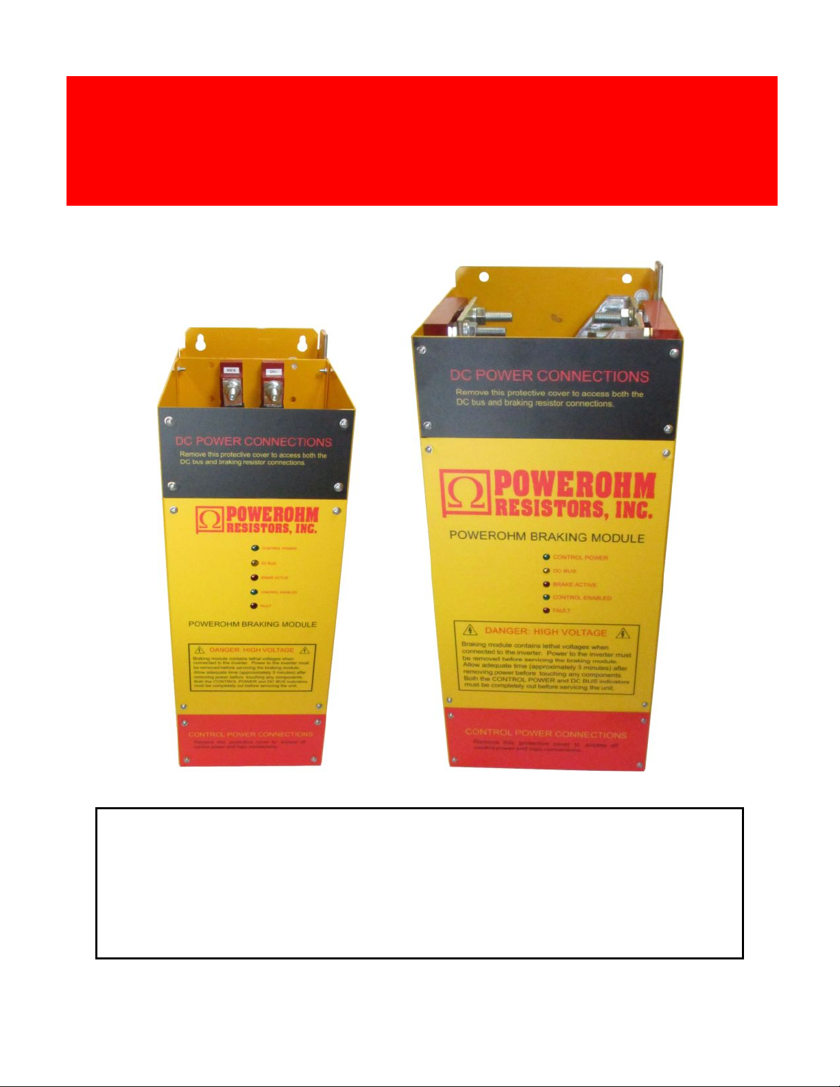
Product Overview
AC variable frequency drives are commonly used with general purpose AC induction motors to
form reliable variable speed drive systems. Problems with these drive systems can occur when an
application requires a deceleration rate faster than what can be managed by the drive alone, or
when motor speeds exceed the synchronous speed set by the output frequency of the drive (which
is called an overhauling load condition). Both of these conditions create regenerated power which
flows from the motor back into the drive, causing its DC Bus to rise. To manage the regenerated
power and avoid shutting the drive down due to an over-voltage trip, this power must be dissipated
by an external braking resistor.
PowerOhm Type BG Braking Modules can be used in conjunction with any AC drive to monitor
the DC bus of the drive and activate external braking resistor as needed not only to avoid overvoltage trips, but to greatly improve the performance of the drive system. The use of Braking
Modules and resistors increase the braking torque capability of a variable frequency drive,
allowing faster and more controlled deceleration times.
To accommodate system horsepower requirements beyond the capability of a single Module,
the Modules are all Master/Slave programmable. This allows an arrangement of multiple Modules
to effectively function as a single higher rated module.
The products covered in this manual are intended to be used with Listed inverter drives. The
input of the DBU is only to be connected across the DC bus of an inverter drive. Conductors for
connection of the DBU shall be according to the NFPA 70 (national Electric Code) and the drives
installation instructions.
4 a brand of ICD, Inc.

Inspection upon Receipt
Environmental Conditions
Upon receipt of your PowerOhm Braking Module, be sure to carefully unpack the module and inspect the unit
carefully for any shipping damage. The module contains electronics that can be damaged by static electricity, so
handle in accordance with industry standards. Check for loose, broken or otherwise damaged parts due to
shipping. Report any shipping damage immediately to the freight carrier. Be sure to verify that the part number and
ratings listed on the nameplate match the order specification and the capabilities of the drive system. The ratings
listed on the nameplate are critical – installing and energizing the incorrect part number could damage the
braking module and/or the drive!
The PowerOhm Type BG Braking Module should be installed in an environment protected from moisture and
excessive dust. Dust buildup can reduce the electrical insulation characteristics of the unit and moisture can cause
arching or shorting. Air must be free of combustible gases and corrosive vapors.
Chassis classification: Open Type
Ambient Temperature Range: -10ºC to 40ºC
Maximum Altitude: 3300 feet (1000m)
Maximum Vibration: 10 to 20Hz, 32ft/sec/sec; 20 to 50Hz, 6.5 ft/sec/sec
5 a brand of ICD, Inc.
PowerOhm
Part No.
Nominal
AC Line
Voltage
Minimum
Ohms
@ listed
Turn ON
Turn ON
Voltage
RMS
Cont
Current
Max
Peak
Current
Max
Watt
Loss
HCPBM208450-(24,AEN,APB)
208
.56
336
450
600
1155
HCPBM240450-(24,AEN,APB)
240
.65
390
HCPBM380450-(24,AEN,APB)
380
1.02
612
HCPBM415450-(24,AEN,APB)
415
1.12
670
HCPBM480450-(24,AEN,APB)
480
1.29
775
HCPBM600450-(24,AEN,APB)
600
1.62
970
HCPBM690450-(24,AEN,APB)
690
1.82
1090
HCPBM720450-(24,AEN,APB)
720
1.87
1120
PowerOhm
Part No.
Nominal
AC Line
Voltage
Minimum
Ohms
@ listed
Turn ON
Turn ON
Voltage
RMS
Cont
Current
Max
Peak
Current
Max
Watt
Loss
HCPBM208600-(24,AEN,APB)
208
.37
336
600
900
1522
HCPBM240600-(24,AEN,APB)
240
.43
390
HCPBM380600-(24,AEN,APB)
380
.68
612
HCPBM415600-(24,AEN,APB)
415
.74
670
HCPBM480600-(24,AEN,APB)
480
.86
775
HCPBM600600-(24,AEN,APB)
600
1.08
970
HCPBM690600-(24,AEN,APB)
690
1.21
1090
HCPBM720600-(24,AEN,APB)
720
1.24
1120
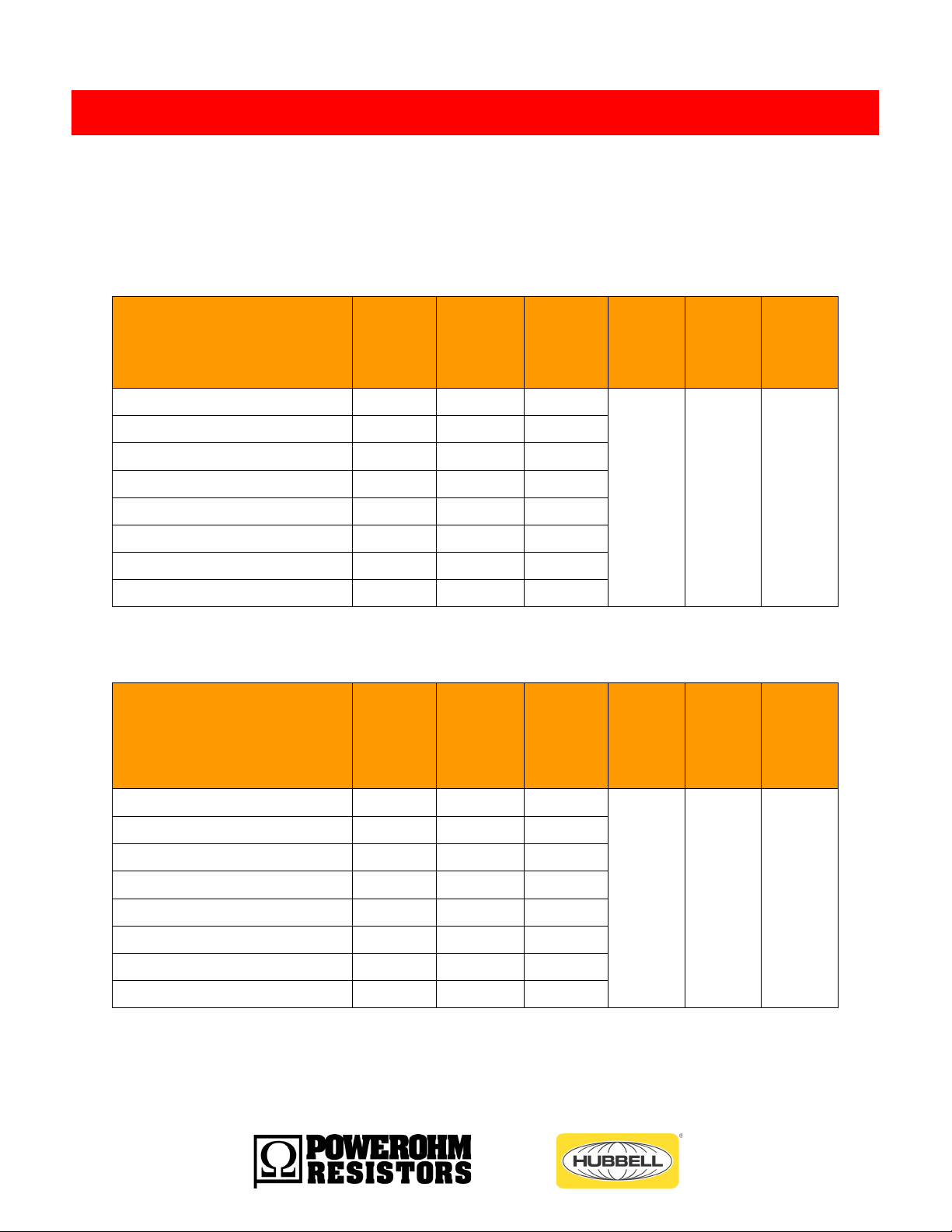
Electrical Ratings
The PowerOhm Type BG Braking Module is available in line voltages ranging from 208 to 720 volts. Peak
currents up to the maximum are allowed at intermittent duty cycles (reference the below tables for details).
Options are designated in the part number after the dash at the end. -24v = 24vdc control power.
-AEN = Acromag Ethernet communications module. -APB = Acromag PROFIBUS communications module.
TABLE 1a: General Specifications for 450 amp Type BG Braking Modules
TABLE 1b: General Specifications for 600 amp Type BG Braking Modules
6 a brand of ICD, Inc.

PowerOhm
Part No.
Nominal
AC Line
Voltage
Minimum
Ohms
@ listed
Turn ON
Turn ON
Voltage
RMS
Cont
Current
Max
Peak
Current
Max
Watt
Loss
HCPBM208900-(24,AEN,APB)
208
.25
336
900
1350
2257
HCPBM240900-(24,AEN,APB)
240
.29
390
HCPBM380900-(24,AEN,APB)
380
.45
612
HCPBM415900-(24,AEN,APB)
415
.5
670
HCPBM480900-(24,AEN,APB)
480
.57
775
HCPBM600900-(24,AEN,APB)
600
.72
970
HCPBM690900-(24,AEN,APB)
690
.81
1090
HCPBM720900-(24,AEN,APB)
720
.83
1120
PowerOhm
Part No.
Nominal
AC Line
Voltage
Minimum
Ohms
@ listed
Turn ON
Turn ON
Voltage
RMS
Cont
Current
Max
Peak
Current
Max
Watt
Loss
HCPBM2081200-(24,AEN,APB)
208
.19
336
1200
1800
2992
HCPBM2401200-(24,AEN,APB)
240
.22
390
HCPBM3801200-(24,AEN,APB)
380
.34
612
HCPBM4151200-(24,AEN,APB)
415
.37
670
HCPBM4801200-(24,AEN,APB)
480
.43
775
HCPBM6001200-(24,AEN,APB)
600
.54
970
HCPBM6901200-(24,AEN,APB)
690
.61
1090
HCPBM7201200-(24,AEN,APB)
720
.62
1120
TABLE 1c: General Specifications for 900 amp Type BG Braking Modules
TABLE 1d: General Specifications for 1200 amp Type BG Braking Modules
7 a brand of ICD, Inc.

Attention: Installation and removal of this equipment should be done by qualified
personnel only. Equipment must be installed in accordance with all applicable
national and local electrical codes and regulations.
Equipment Installation
The PowerOhm Type BG Braking Module should be installed on a low vibration surface that is non-flammable.
MOUNTING REQUIREMENTS
To allow proper cooling, it is very important to install the fan cooled PowerOhm braking modules in a location
with an ambient temperature not exceeding 40 degrees Celsius or below 0 degrees Celsius. Modules should
be installed in an environment with sufficient circulation of clean, dry air. The module should be installed in an
area allowing a minimum of 6 inches of free space above and below the frame, and 2” on both sides to allow
proper airflow and cooling.
POWER EARTH GROUNDING
A good earth ground is essential in today’s PWM drive installations. The PowerOhm brake module should have
a dedicated Power Earth ground wire that runs directly to the drive PE ground to mitigate drive system noise.
Each drive and cabinet should be properly earth grounded, with all safety grounds connected directly to PE
ground. Excessive common mode noise may need to be shunted to PE ground.
CONTROL EARTH GROUNDING
In order to minimize the effects of drive system noise it is recommended that the control power supply and I/O
INPUTS not be tied to earth ground. If they must be tied to earth for other system components, use a clean
earth ground.
8 a brand of ICD, Inc.
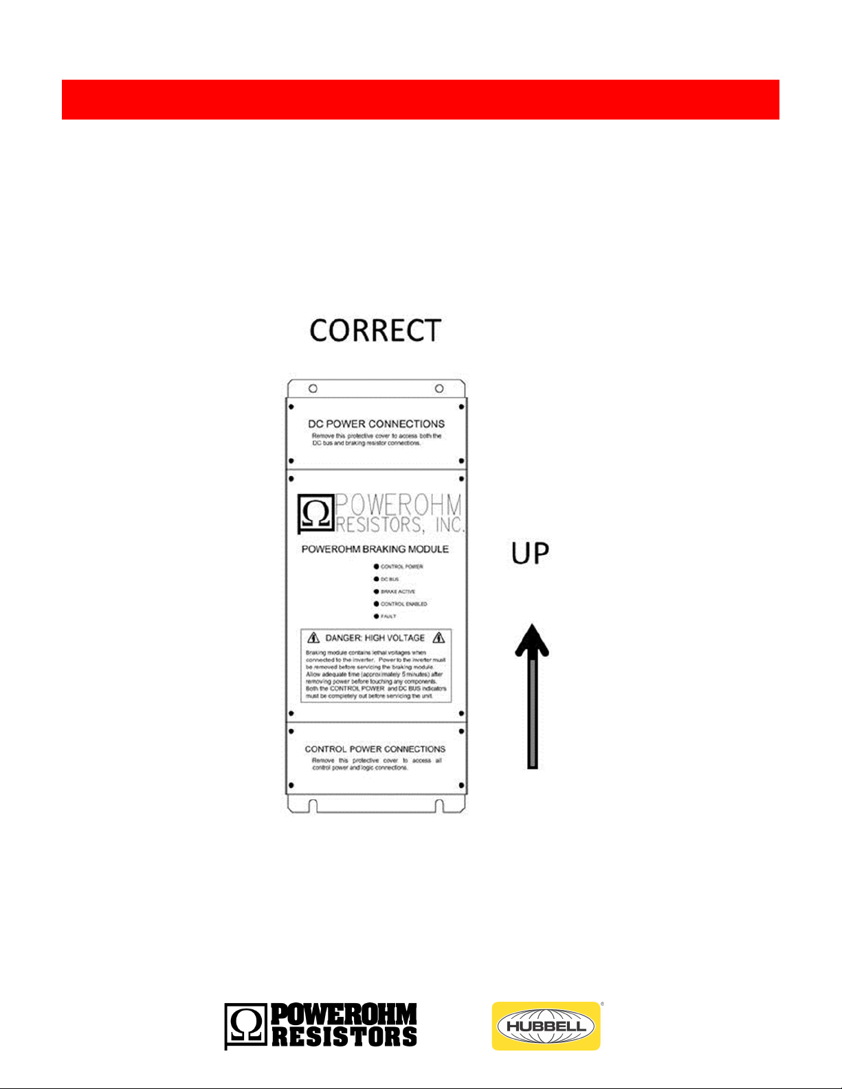
Mounting Orientation
The PowerOhm BG Series Braking Module must be installed in a vertical position in order to meet published
current ratings. (see Figure 1).
FIGURE 1: Mounting Orientation for BM Braking Modules
9 a brand of ICD, Inc.
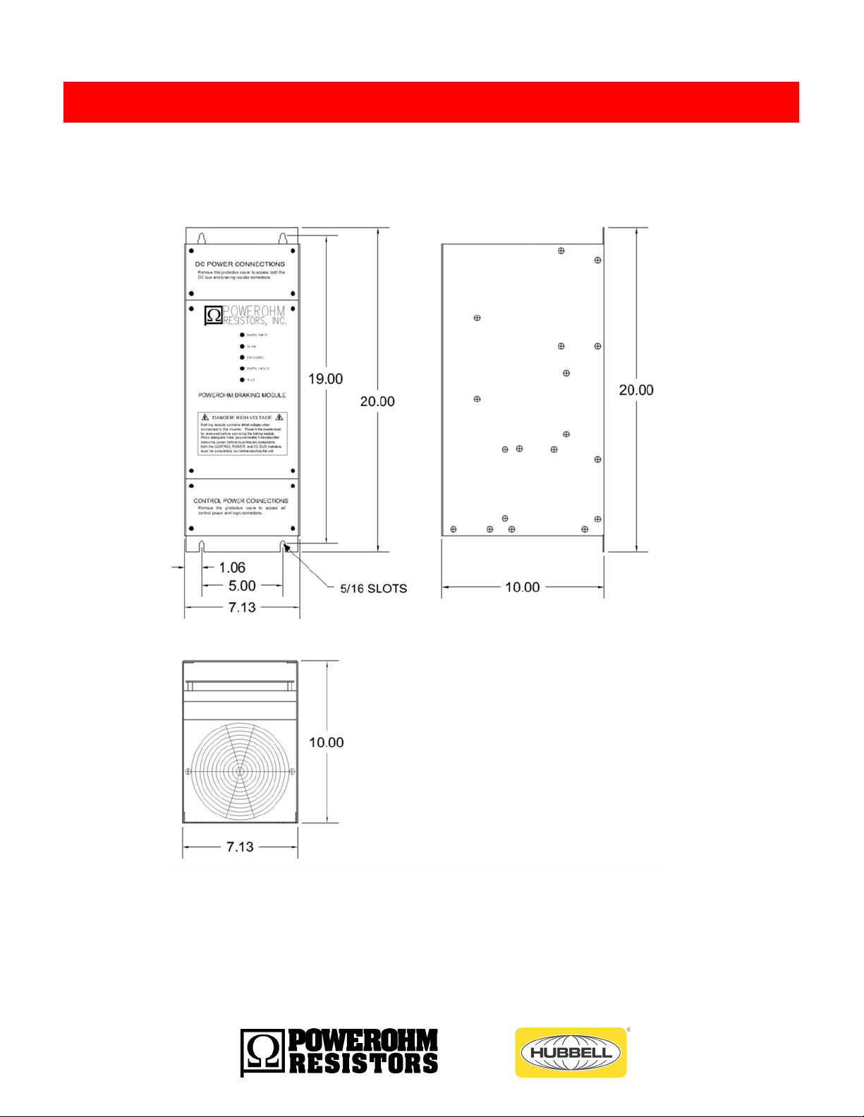
Dimensions and Weight
FIGURE 2a: Braking Module Dimensions for 450 & 600 amp Models
Weight: The weight of the 450 amp unit is 30lbs and the 600 amp is 34 lbs.
10 a brand of ICD, Inc.
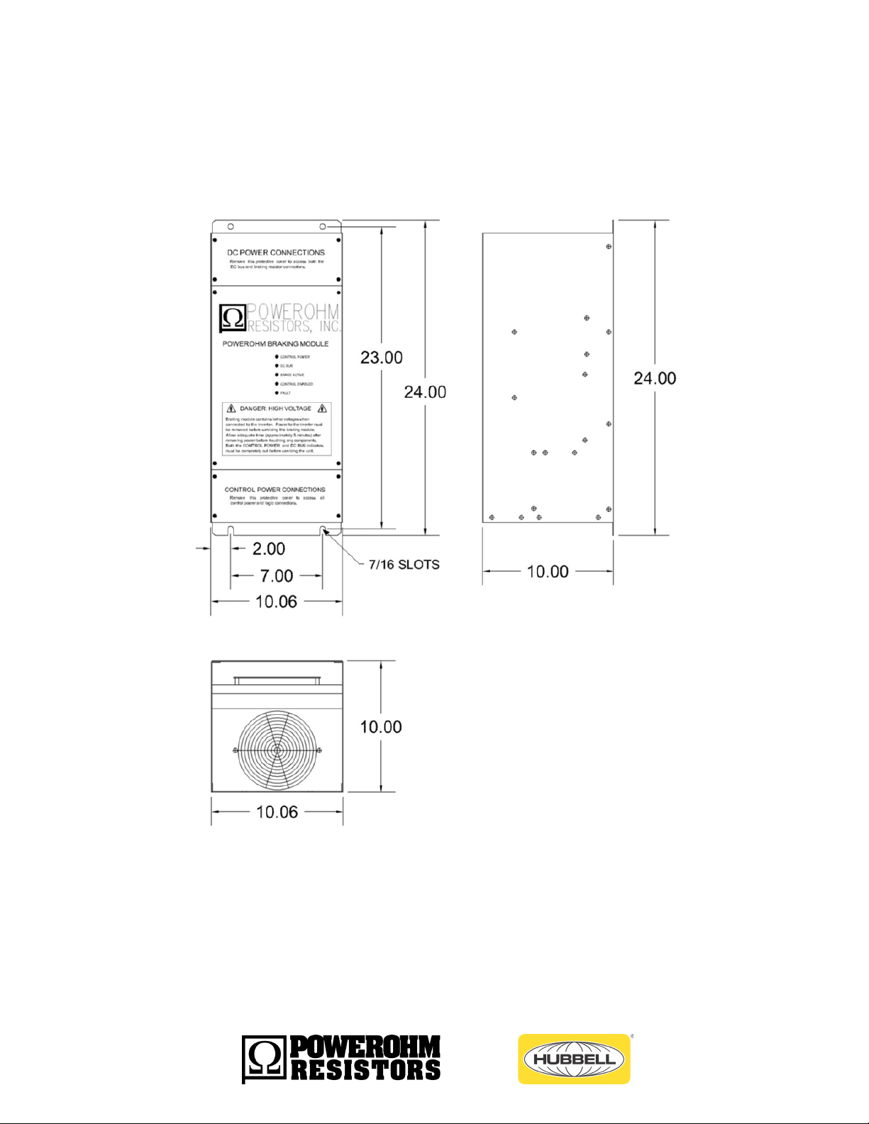
FIGURE 2b: Braking Module Dimensions for 900 & 1200 amp Models
Weight: The weight of the 900 amp unit is 55lbs and the 1200amp is 60lbs.
11 a brand of ICD, Inc.
Important: Always properly ground each component to Power Earth ground (PE). Ground Brake Module
DIRECTLY to AC Drive Module Power ground, and ensure the drive cabinet has a good ground.
WARNING: Never install a braking resistor directly across the DC bus of the drive.
Drive damage or failure may occur upon applied power. Additionally, without the
braking module to activate and deactivate the braking resistor, the resistor will
dissipate power continuously and be subject to overheating and failure.
Wiring Recomendations
It is recommended that the AC drive manual, braking resistor instructions and any other pertinent
documentation be thoroughly reviewed before proceeding.
NEVER bundle power wires and control wires together. Control and power wiring should be separated to avoid
electrical noise and interference problems. The responsibility for proper wiring lies with the machine builder.
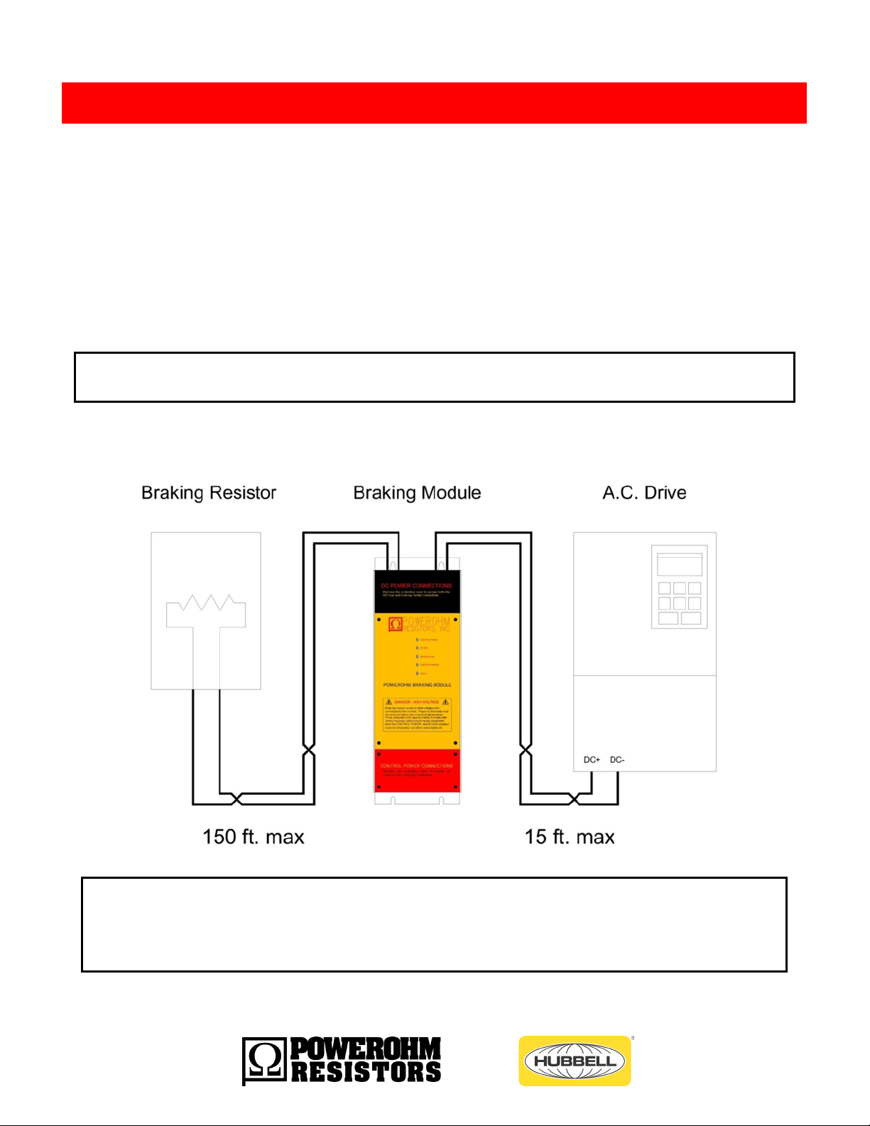
The wiring between the drive and braking module should not exceed 15 feet and between the braking resistor
and braking module should not exceed 150 feet.
Use CU conductors only with insulation rated for 75° C minimum or equivalent.
Figure 3: Power Wiring Lengths Between Drive System Components
12 a brand of ICD, Inc.
MOTOR HP @ 10% DUTY CYCLE
MIN
WIRE
SIZE
240VAC
480VAC
600VAC
50HP-100HP
100HP to 200HP
100HP to 200HP
4awg
100HP to 200HP
300HP to 500HP
300HP to 500HP
1/0
N/A
500HP-1000HP
500HP-1000HP
4/0
MOTOR HP @ 30% DUTY CYCLE
MIN
WIRE
SIZE
240VAC
480VAC
600VAC
50HP-100HP
100HP to 200HP
100HP to 200HP
2awg
100HP to 200HP
300HP to 500HP
300HP to 500HP
2/0
N/A
500HP-1000HP
500HP-1000HP
350kcm
ATTENTION: The National Electric Code (NEC) and local regulations govern the
installation and wiring of electrical equipment such as braking resistors and
modules. DC power wiring, AC power wiring, control wiring and conduit must be
installed in accordance with all applicable codes and regulations.
Wire Sizing
The National Electric Code (NEC) and local regulations govern the installation and wiring of electrical
equipment such as variable frequency drives, braking resistors and braking modules. DC power wiring, AC power
wiring, control wiring and conduit must be installed in accordance with all applicable codes and regulations.
Reference Table 2 for suggested minimum wire sizes only. Keep in mind the duty cycle rating greatly affects the
minimum wire size needed.
TABLE 2: Wire Sizing for Power Interconnections
Note: 18 AWG wire is sufficient for all control and signal wiring
13 a brand of ICD, Inc.
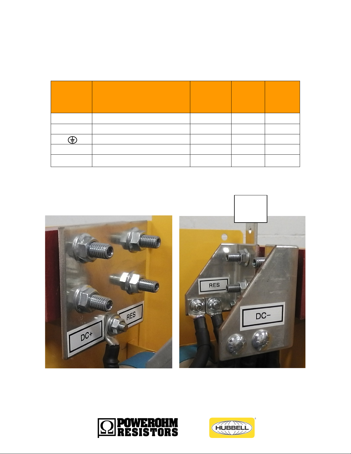
Terminal
Designation
Terminal Description
Connection
Type
Socket
Size
Max.
Torque
(lb-ft)
DC -
DC Bus Connection (Negative)
3/8” studs
9/16”
20
DC+
DC Bus Connection (Positive)
3/8” studs
9/16”
20
Ground Connection
3/8” hole
-
-
RES -
Braking Resistor IGBT Connection
3/8” studs
9/16”
20
RES+
Braking Resistor DC+ Connection
3/8” studs
9/16”
20
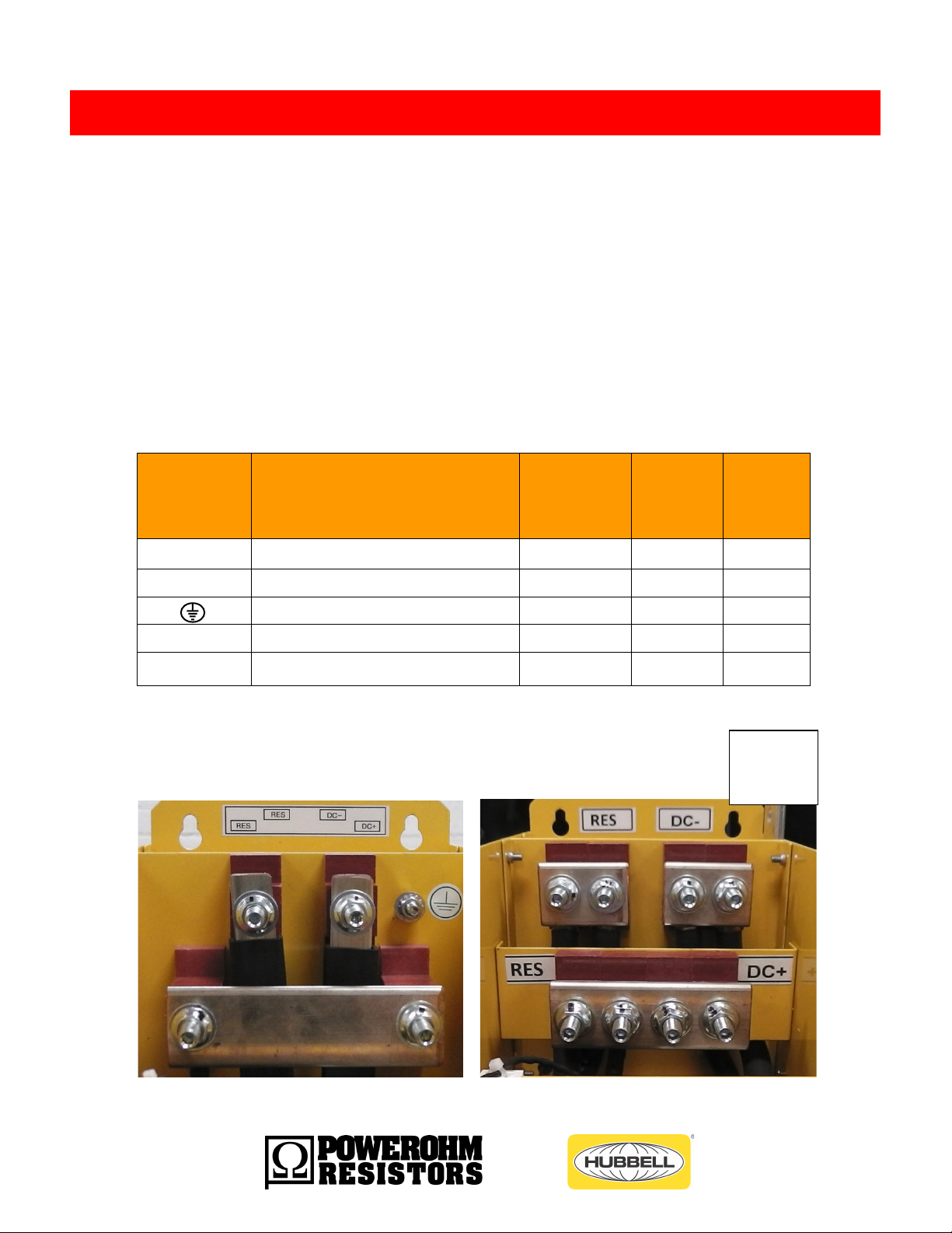
Power Connections
Power
Earth
Ground
POWER CONNECTIONS
• The PowerOhm Type BG Braking Module features a total of five power connections.
• Field wiring to studs must be made by a UL listed clamp or closed terminal connector
• sized for the wire gauge involved
• Run both resistor leads direct to the RES+ and RES – terminals.
• Run both DC bus leads from drive direct to the DC+ and DC – terminals.
• Keep away from all control wiring and cross at 90deg angles at least an inch away.
TABLE 3a: Descriptions of Power Connections for 450 & 600 amp
450amp 600 amp
14 a brand of ICD, Inc.
Terminal
Designation
Terminal Description
Connection
Type
Socket
Size
Max
Torque
(lb-ft)
DC -
DC Bus Connection (Negative)
Two ½” studs
¾”
50
DC+
DC Bus Connection (Positive)
Two ½” studs
¾”
50
Ground Connection
3/8” hole
-
-
RES -
Braking Resistor IGBT Connection
Two ½” studs
¾”
50
RES+
Braking Resistor DC+ Connection
Two ½” studs
¾”
50
Power
Earth
Ground
TABLE 3b: Descriptions of Power Connections for 900 & 1200 amp
900 & 1200 amp
15 a brand of ICD, Inc.
 Loading...