

Powernail PowerStapler 445FS Operation And Maintenance Manual
POWERNAIL® CO.
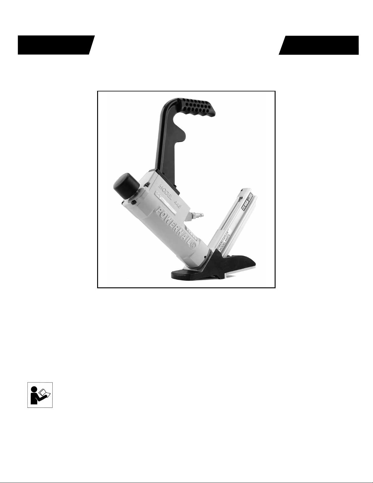
Models 445FS Pneumatic PowerStapler™
OPERATION AND MAINTENANCE MANUAL
MANUAL DE OPERACION Y DE MANTENIMIENTO
MANUEL D’INSTRUCTIONS ET D’ENTRETIEN
WARNING
Read this manual before you use this PowerStapler®. Follow all safety warnings and
instructions. If you are uncertain about the operation of the stapler, call us directly
at 1-800-323-1653 for assistance or contact the closest Powernail Dealer for help.
Please retain this information for future reference.
rev. 2019.04.09

INTRODUCTION
The PowerStapler® Model 445FS Mallet Actuated Pneumatic Stapler is designed to bring Powernail
quality to a pneumatic stapler. For those looking for ease of use in a pneumatic tool, the PowerStapler
Model 445FS provides several distinct advantages. The Model 445FS can staple 3/4” fl ooring down to
1/2” tongue and groove hardwood fl ooring through the use of easy-to-change, no-mar adapter plates.
The Model 445FS is designed for use with 1-1/2”, 1-3/4” and 2” PowerStaples®.
INDEX
Index..................................... 2
Warranty............................... 2
Safety Instructions................ 3
Powernail Company Info...... 3
Operating Instructions.......... 4-5
Parts & Service.................... 4-7
Drive Blade Change ............ 5
Seal Replacement................ 5-7
Seal Locations Diagram....... 10
Schematic ........................... 11
Safety Labels........................ 12
Troubleshooting Chart......... 13
Depth Chart.......................... 14
Fasteners............................. 15
Accessory Products.............. 16
Parts List.............................. 8-9
LIMITED WARRANTY
POWERNAIL® Company, Inc. warrants to its customer, and to the fi rst end-use purchaser of
POWERNAIL fl ooring nailers purchased from an authorized POWERNAIL distributor, that
each serialized manufactured nailer by POWERNAIL®, for a period of 12 months from the date
of purchase, and with respect to the nailer/stapler body (specifi cally Models 200, 445, and 50P),
for a period of 10 years from date of purchase, (“warranty period”); shall be free of defects in
materials and workmanship and will meet POWERNAIL’s specifi cations in eff ect at the time of
Product shipment. POWERNAIL will repair or replace, at its option, any Powernailer® that does
not conform to this warranty. Claims must be made no later than fi fteen (15) days after the end
of the warranty period. POWERNAIL will perform all repair or replacements itself or through
its authorized contractors. POWERNAIL is not responsible for shipping, labor or other direct or
indirect costs. Damage caused by abuse, misuse, unusual or excessive wear is excluded. Repair
or modifi cation of the Products by unauthorized parties will void this warranty. The customer
is responsible for returning Products to POWERNAIL for verifi cation of nonconformance.
Warranties for Products not manufactured by POWERNAIL are limited to warranties provided
to POWERNAIL by the manufacturer of such product that are assignable to customer.
THESE WARRANTIES AND REMEDIES ARE EXCLUSIVE OF ALL OTHERS, EXPRESS
OR IMPLIED. THE WARRANTIES OF MERCHANTABILITY AND FITNESS FOR
PURPOSE ARE EXPRESSLY EXCLUDED. IN NO EVENT SHALL POWERNAIL’S
LIABILITY FOR A WARRANTY CLAIM EXCEED THE PRICE PAID TO POWERNAIL
FOR THE NONCONFORMING PRODUCT, REGARDLESS OF THE FORM OR BASIS OF
THE CLAIM OR CAUSE OF ACTION.
2
SAFETY INSTRUCTIONS
Always use approved SAFETY GLASSES and EAR PROTECTION when operating this stapler. The
operator and others in the work area should always wear approved FRONT and SIDE eye protection
when operating this stapler. Eye protection will help guard against fl ying staples and debris, which could
cause severe eye injury.
EYE AND EAR PROTECTION should be used to prevent hearing damage when there are high noise
levels in the work area.
ALWAYS use ear plugs with a noise reduction rated at 29 db or highter at a construction site.
Stapler noise ratings are at LPA-1sd=90.6,
LWA-1sd=99.3 and LPA-1s,1m=86.3.
Stapler vibration rating: m/s2=3.05.
Always DISCONNECT THE AIR SUPPLY before making any adjustments, repairing, clearing jams or when the
stapler is not in use. Do not use on scaff olding or ladders and disconnect stapler from air supply when transporting
between installation areas.
Never attach the female end of a quick disconnect to the stapler. This will trap air inside the Stapler and permit it to
be discharged. Only the unrestricted male connection should be attached to the Stapler.
Stapler requires an air source that can continuously deliver 80 to 110 psi at 3-1/2 cubic feet of air per minute for
operation.
Normal air pressure should not exceed 120 psi or damage to the Stapler and seals may occur. Excess air
pressure can cause the Stapler to explode.
To prevent fi re or explosion, use only regulated compressed air—do not use bottled gases of any kind (no oxygen
or combustible gasses) to power this Stapler.
Stapler is intended for use installing wood fl ooring and is not to be used for purposes not specifi ed in the
operations manual.
Do not use any nails other than Powernail Powercleats Nails which are specifi cally designed for use in any
Powerstapler. Powercleats Nails are available in various lengths. Contact your Powernail Dealer for Powercleats
Nails.
Use only Powernail replacement parts in the repair or maintenance of this stapler. Parts or repair services are
available from the manufacturer or from agents authorised by the manufacturer. Repairs should be carried out
only by trained service personel in the fi eld of fastener driving tools who will observe proper safety controls while
performing maintenace. Service personel should be qualifi ed to to asses the safe working condition of fastener
driving tools.
Never place any part of the body in the discharge path of the Stapler when air is connected to the Stapler. Always
make sure Stapler is empty of cleats before connecting air hose so as to prevent any accidental discharge from
occurring.
Never leave the Stapler unattended while it is connected to an air supply.
Whenever air is connected to the Stapler, keep body parts away from the nail discharge path.
Disconnect the air line before making adjustments or repairs on the Stapler. Only connect air to an
unloaded Stapler so as to prevent accidental discharge.
POWERNAIL COMPANY, INC.
1300 Rose Road, Lake Zurich, IL 60047 US
Phone: 1-800-323-1653 OR 847-847-3000
www.powernail.com
3

OPERATING INSTRUCTIONS
Consult the staple depth chart for the appropriate
adapter pad to use with the thickness of fl ooring
you are installing and the selection of Powerstaple®
length.
Rack the fl ooring into place with the rubber end of the
mallet supplied with the Stapler
Place the Stapler Adapter Foot on the tongue-edge of
the fl ooring strip to be stapleed. Be sure the Adapter
Foot is pressed tightly against the edge of the fl ooring
strip above the tongue.
Be sure fl ooring strips are racked tightly. Tap the
Stapler Plunger Rubber Cap with the rubber capped
end of the mallet to discharge the Stapler.
WARNING: It is not necessary to hit the Stapler hard
to activate it. Never hit the Stapler with excessive
force or with the metal end of the mallet, this will
damage the Stapler.
DO NOT USE THE METAL END OF THE MALLET
TO STRIKE THE PLUNGER, use the rubber capped
end only.
Before each use, check all screws to be sure they are
tight. Shock and vibration can loosen screws. Do not
over tighten any screw.
AIR SUPPLY:
The air must be clean and dry. Dirty and/or wet air will
damage the Stapler.
Drywall Dust:
• Using Pneumatic PowerStaplers in drywall dust
conditions will dramatically decrease the life of the
Stapler.
• Drywall dust is abrasive, when cycled through
the Stapler it will cause excessive wear.
The air source must continuously deliver 80 to 110
psi at 3-1/2 cubic feet of air per minute to operate
the Stapler. For operation, connect a 1/4” minimum
internal diameter and clean air hose to the Stapler.
Be sure the air regulator is set at 90 psi. If the staple
is not countersunk below the surface of the wood, turn
up the air pressure, but not over 110 psi.
Check for air supply leaks that waste air and starve
the Stapler of air thereby reducing its performance.
There should be no orifi ce smaller than 1/4” in the air
path between the Regulator and the Stapler.
of Air Tool Oil, supplied with your Stapler, into the
disconnected air line male connector attached to the
Stapler.
WARNING: Do not over lubricate the Stapler, excess
oil mist or drops will be vented with spent air when over
lubricated. Excess oil could stain the wood fl ooring,
walls or furnishings. Dry fi re the Stapler, without staples,
to purge excess oil, before you begin to staple down
fl ooring. Before storing the Stapler, lubricate and cycle
the Stapler in insure internal parts are oil protected from
corrosion.
WARNING: Detergent oil is not recommended and may
damage the seals.
TO LOAD MODEL 445FS:
Place two sticks (90 PowerStaples) into the Staple
Channel feed slot. Pull back the spring loaded Staple
Pusher over the staples until it contacts the last staple
and slowly release the Staple Pusher.
TO UNLOAD MODEL 445FS:
To remove staples from the Staple Channel, pull the two
round knobs on the Staple Pusher together. This will
clear it from the staple path. Then turn the Stapler over
so the staples slide out of the channel.
LUBRICATION:
You must lubricate the Stapler manually. The
frequency of lubrication is dependent upon the duty
cycle of the Stapler. Continuous duty requires more
frequent oiling than intermittent duty.
At least every eight (8) hours place two to four drops
4

OPERATING INSTRUCTIONS, continued
OPERATING STAPLER:
To use the Model 445FS, simply place the stapler on the
fl oor, pull nailer back so locating ears catch the edge
of the fl oor above the tongue, tap the plunger with the
rubber capped mallet end and let the stapler drive and
set the staple at the correct 45 degree angle.
Adjust stapler by adding shims between the adapter foot
and pad until there is a slight gap between the tongue of
the wood and the locating ears of the adapter foot. See
example 1B and 2A.
PARTS & SERVICE:
When ordering parts include the part number, part
description, PowerStapler model and serial number. Be
sure to state the quantity of the part(s) required. Contact
your Powerstaple Dealer for the necessary parts.
WARNING: Never work on the Stapler if the air line
is attached. Always disconnect the air line from the
Stapler fi rst.
Stapler DISASSEMBLY:
TO REPLACE RUBBER BUMPER (#24):
1.) Disconnect the air supply
2.) Remove the four (4) screws holding the Adapter
Foot, Foot and Staple Channel assembly to the main
Body.
3.) Pull the Rubber Bumper out of the cylinder bore.
Replace the old Bumper if it shows signs of wear or it
is split.
4.) Reverse these steps to reassemble the Stapler.
Be sure to align the Driving Blade with the slot in the
Staple Channel Assembly while you reassemble the
Stapler.
NEVER FIRE THE Stapler WITHOUT THE RUBBER
BUMPER INSTALLED, IT WILL SEVERELY DAMAGE
THE STAPLER.
CHANGING A DRIVING BLADE (#15):
1.) Disconnect the air supply.
2.) Remove the four socket head cap screws (#40)
holding the Adapter Foot (#60), Foot (#30) and Staple
Channel Assembly (#27) to the body.
3.) Remove the Rubber Bumper (#24).
4.) Pull the Driving Blade (#15) with pliers until the
Piston (#20) is fully extended outward towards the
bottom of the cylinder.
5.) Use a 15/16” box wrench (Part #:
unscrew the Driving Blade Jam Nut (#22) and remove
it. Hold the Piston from turning while unscrewing the
Jam Nut by holding the piston hex with a 1-1/8” box
wrench
(Part #:
6.) Push out the 1/4” diameter blade retaining Dowel
Pin (#14) and remove the broken Driving Blade stub.
7.) Install a new Driving Blade in the slot and replace
the Dowel Pin (#14). Screw on the retaining Jam Nut
(#22) using the same tools. If the Jam Nut becomes
worn and loose after frequent removals, it should be
replaced.
8.) Check the fi t, there should be some sideways
movement between the Driving Blade and the Jam
Nut assembly. This is desirable and helps the blade
to align itself with the mating parts.
9.) Reassemble the components. Be sure to align
the Driving Blade with the slot in the Adapter Foot
Assembly.
09-44529768).
09-44529768) to
5
 Loading...