

Page 1
第 1 页 共 16 页
Safety Instruction
AHE58-55 Instruction Manual
1 Installation Instructions
1.1 Product specifications
Product Type: AHE58-55; maximum motor speed: 5000 r / min; Supply Voltage: AC 220 ± 44
V; Power frequency: 50Hz/60Hz; Maximum output power: 550W; maximum motor torque: 3Nm.
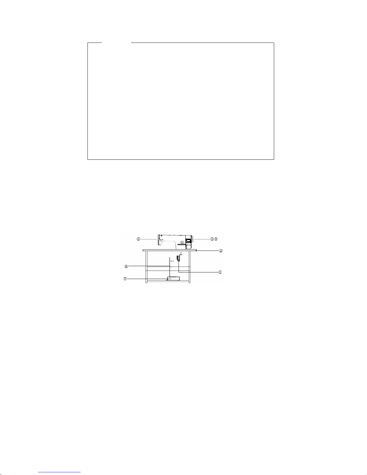
1.2 Pedal installation
First, With self-tapping screws fastening the pedals①under the proper position of the platen
②.(direct drive servo motor ③and control box④has been fixed on the s ewing ma chine head⑤).
Then the two ends of the pedal connecting rod⑥ are connected wit h the pedals① and the
bottom pedal⑦.
Fig.1-1 Direct drive machine controller installation diagram
· Please read this manual carefully, also with related manual for the machinery before
use the controller.
· For installing and operating the controller properly and safely, qualified personnel
are required.
· Please try to stay away from arc welding equipment, in order to avoid
electromagnetic interference and malfunction of the controller.
· Keep in room bellow 45° and above 0°
· Do not humidity below 30% or above 95% or dew and mist of places.
· Install the control box and other components, turn off the power and unplug the
power cord.
· To prevent interference or leakage accidents, please do the ground work, the power
cord ground wire must be securely connected to an effective way to earth..
· All parts for the repair, provided by the Company or approved before use.
· performing any maintenance action, you must turn off the power and unplug the
power cord. There are dangerous high voltage control box, you must turn the power
off after one minute before opening the control box.
· This manual marked with the symbol of the Department of Safety Precautions must
be aware of and strictly adhered to, so as not to cause unnecessary damage.
Page 2
第 2 页 共 16 页
:The footboard trys to ensure that the installation position is vertical rod pedals,
the operator pedal is more comfortable and flexible.
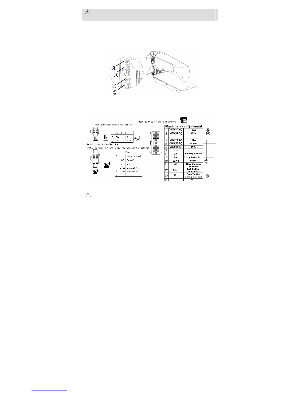
1.3 Interface plug connections
The pedals and the machine head of the connector plug are mounted to the corresponding
position in the controller back of socket, the name of each socket shown in Figure 1-2. Once
connected, please check if the plug is inserted firmly.
Fig.1-2 Controller Interface diagram
①Pedals; ②Foot lifter solenoid socket ; ③ Machine head solenoid socket; ④Mac hine head
light socket (black);
Fig.1-3 Controller Interface Definition
:If the plug does not go in, check the plug an d socket matches, n eedle inse rtion dir ectio n or
the direction is correct! Light socket and presser foot lifter solenoid interfaces are 1 * 2
interface, head lights black connector interface, please note that distinction.
1.4 Wiring and Grounding
Must prepare the system grounding project, please be a qualified electrical engineer
construction. Product is powered and ready for use, you must ensure that the power outlet the
AC input is securely grounded. System grounding wire is yellow and green lines, make sure the
ground wire is connected to the grid and reliable security protection on the ground to ensure the
safe use, and prevent abnormal situation.
Page 3
第 3 页 共 16 页
:All power lines, signal lines, ground lines, wiring not to be pressed into other
objects or excessive distortion, to ensure safe use!
2 Operation Panel Instruction
2.1 Operation Panel Display Instruction
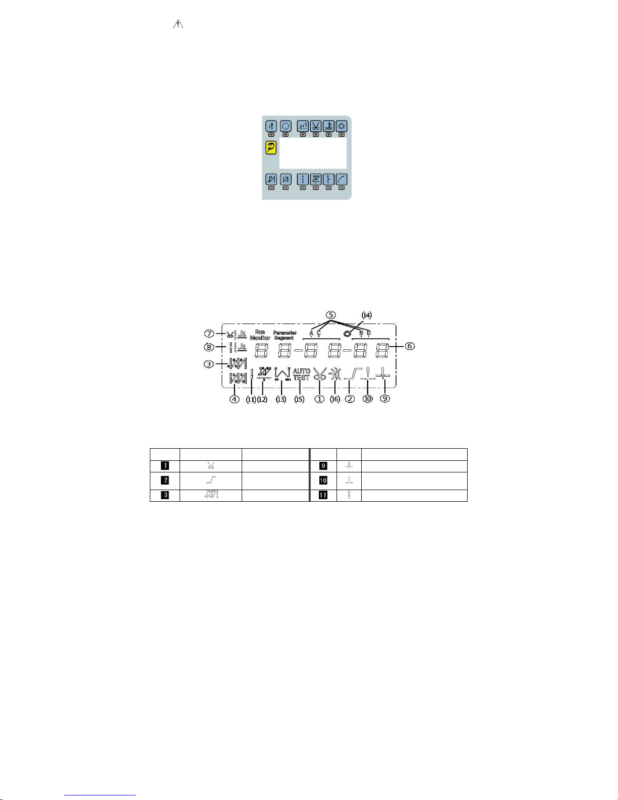
2.1.1 The operation panel composition
Operation Panel is divided with two areas(See Fig2-1):LCD display areas and key words area.
Fig.2-1 Operation Panel
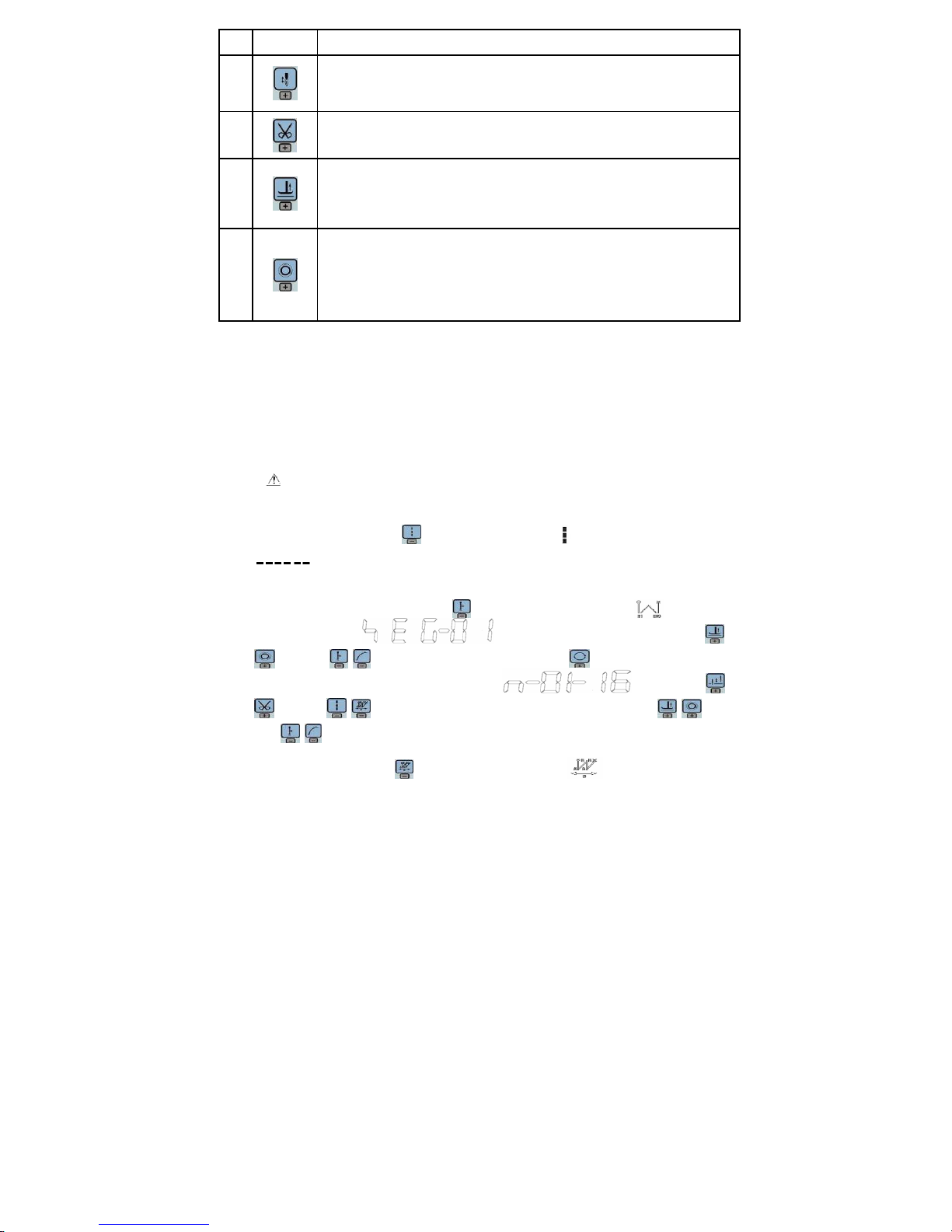
2.1.2 The LCD display
The LCD display areas are position in middle of the whole operation panel. It including pattern,
sewing mode, start/end back tacki ng , and foot lifter, stop-n eedles and trimming, and slow start
operation set. The operation system aut omatically power on that HMI will a self-test, then all icons will
flash once in the LCD display areas and only display the current settings of the system, the other did
not choose that the icon will not be lighted, see figure 2-2.
Fig.2-2 LCD Icon
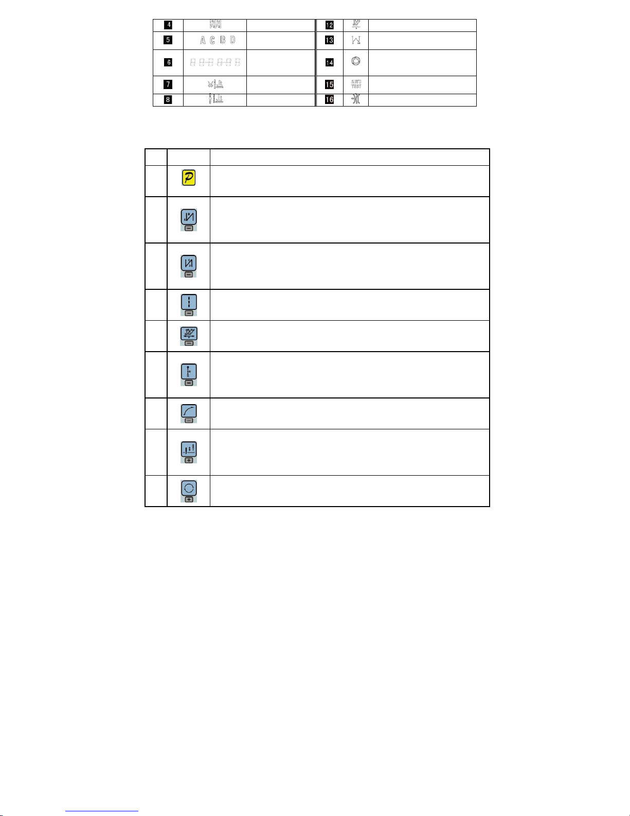
Table 2-1 LCD Icon Display Description
Index
Icon Description Index Icon Description
Automatic trimming
Intermediate stops up stop position
Soft-start function
Intermediate stops down stop
position
start back tacking
Free sewing
Page 4
第 4 页 共 16 页
End back tacking
W seam
Sewing segments
index
Multi-seam
Numeric character
display (pin number /
parameter)
Trigger function
Footlifter after
trimming
Automatic test
Middle stop footlifter
Clamp function
2.2 The operation panel keys of description
A description of each key operation panel shown in Table 2-2.
Table 2-2 : Key Functions instruction
No Appearance
Description
1
Function key:Major operation to determine and confirm working, and work with other key to set
a higher level of the parameter.
2
start back tacking key:Every effective press the key once; round with single start back tacking,
double start back tacking, four start back tacking and close start back tacking. The current status
is displayed on the left of LCD.
Detailed see "3.1.2 before and after sewing settings instruction.
3
end back tacking key:Every effective press the key once; round with single end back tacking,
double end back tacking, four end back tacking and close end back tacking. The current status is
displayed on the left of LCD. Detailed see "3.1.2 before and after sewing settings instruction.
4
Free sewing mode key:Every effective pushed the key once; the system selects free sewing
mode. The free sewing status is displayed below LCD.
Detailed see "3.1.1 model sets of sewing."
5
W sewing mode key:Every effective pushed the key once; the system selects W sewing mode.
The W sewing status is displayed below LCD screen. Detailed see "3.1.1 model sets of sewing."
6
Multi-segment sewing mode key: Every effective pushed the key once; the s ystem selects
multi-segment sewing mode, pressed P key into the number of the needled setting. The
multi-segment sewing status is displayed below LCD. Detailed see "3.1.1 model sets of sewing."
7
Soft start key: Select soft start function. It will show soft start status on top of LCD screen.
8
Stop position key:Select up/down stop position. The up/down stop position is displayed on top
of LCD screen. Detailed see "3.1.7 stop position set. [Note: automatic trimming back, the system
is always on the up of needle position.]
9
Cycle key:Switch parameter position when change parameter;
Page 5
第 5 页 共 16 页
No Appearance
Description
10
Stitch compensation key:Start stitch compensation if press, stop stitch compensation if loose.
11
Trimming key:Select/Cancel automatic trimming. The trimming status is displayed on top of LCD
screen. Detailed see "3.1.5 trimming set.
12
Press foot lifting key: Every effective pushed the key once; round with trimming after press foot
lifting, sewing end press foot lifting and manual press foot lifting. The current s tatus is displayed
on top of LCD screen. Detailed see "3.1.4 press foot lifting set.
13
One-Shot-Sewing key:Select/Cancel one-Shot-Sewing, it is effective only into multi-segment
sewing mode, when chose one-shot sewing, one-shot foot pedal can complete one needle of
multi-segment sewing;The one-shot-sewing status is displayed on top of LC D screen. Detailed
see "3.1.6 trigger set.
3 System Parameter Setting Description
3.1 Operator Mode
In this mode, various sewing modes are available after technical parameters settings. As the
default setting, the system enters this mode when it starts. Under this mode, such basic
functions as normal sewing work and modes change can be realized but no change inside
parameters and setting.
:During working, if long time without press button, HMI will change to idle status
automatically, and will cancel the operation before.
3.1.1 Sewing Mode Setup
·
Free sewing mode:Press key, free sewing mode icon is lightened in LCD area. LCD
indicates free sewing mode has been selected; it is ready just step the pedal for
operation.
· Multi-segment sewing mode:Press key, constant-stitch sewing icon is lightened
in LCD area. LCD is multi-segment sewing status。 Use
keys and keys to choice the N segm ent, an d pres s key to en tr y m u lt i -s e g me nt
sewing stitch number of ea ch s egm ent s et up status . You may use
keys and keys to choice the need to modify number of segment, us e keys
and
keys to modify number of needle in multi-segment sewing stitch setup status.
· W sewing mode: Press key, constant-stitch sewing icon is lightened in LCD area.
Page 6

第 6 页 共 16 页
LCD
is W sewing setup status. You may use keys and keys to
choice needle in A area and set rang 1-99 stitches; use keys and keys to choice
needle in B area and set rang 1-99 stitches. Press key, can be used to choice A B D segment,
LCD , use keys and keys to choice needle in B area and set rang 1-99
stitches.
3.1.2 Start/End back tacking setup:
Step 1: Press key
Start back tacking has following four modes:
None start back tacking
Single start back tacking
Double start back tacking
Four start back tacking
Step 2: Stop pressing to confirm, then this back tack ing mode has bee n sel ect ed.
Step 3: Change the corresponding parameters A values by using
keys and keys
and B values by using
keys and keys. The value range is 1-99 stitches.
It set pin number to be completed before star back tacking.
Note: End back tacking setting method is similar with start back tacking setting method
basically, except the key.
3.1.3 Soft start setup:
Press key, entry into soft start status. If choice soft starts, the icon is lightened in LCD
areas. Press this key again to exit soft start status, the icon will off.
3.1.4 Press foot lifting key:
Press key, entry into foot lifting status, total four different status, no automatic foot lifting、
automatic foot lifting after trimming ( )、 automatic foot lifting if stop during sewing( )
automatic foot lifting if trimming and stop during sewing. Use key to choice foot lifting setup
status and stop press key to confirm. Foot lifting had compiled.
3.1.5 Trimming key
If press key entry into press trimming status, select/non-select trimming. Press key
Page 7

第 7 页 共 16 页
repeat, the icon
is lightened/ disappeared in LCD area. Whether it choice trimming that the
icon is lightened or disappeared.
3.1.6 One-Shot-Sewing key
Use key: select/non-select one-shot-sewing statues. The icon will light if select
one-shot-sewing in LCD areas, press will disappear.
3.1.7 Stop position key
Use key: select up/down stop position. Press key repeat, between up /down
stop position to switch. Choose nee d to stop position and stop press key to confirm. Stop
position had compiled.
3.1.8 Stitch compensation key
Use key : pre ss th is key to start stitch compensation. Compen satio n half need le or a h alf ne edle
due to the press time. If you keep press that compensation needle always until release button.
3.2 Technician Mode
Technician mode is used for sewing speed and pedal speed control such as the use of
performance adjustments.
3.2.1 How to enter the technician mode
Step 1: Under operator mode, press key and key, the LCD will display PD 0000, and then set
the password 0000 to enter technician mode.
Step 2: Use keys and keys to inpu t the password, and then
press key. If the password is correct then enter technician mode, the LCD will display
00 0200 ,otherwise, it will return to operator mode.
Step 3: Change technician parameters by keys and keys. The parameters are
shown in table 2.
Step 4: Parameters values can be changed by keys and keys
Step 5: Under technician mode, press key, the panel will return to operator mode.
3.2.2 Technician mode parameter:
Table3-1:Technician mode parameter
Mode
Parameter
Default
Rang Comment
0 0 200 100 ~800 Minimum sewing speed
01 3500 200 ~5000
Maximum sewing speed
0 2 3000 200 ~5000
Maximum constant sewing speed
0 3 3000 200 ~5000
Maximum manual back tacking speed
0 4 200 100 ~800 Stitch compensation speed
0 5 250 100 ~500 Trimming speed
speed
0 6 0 0 /1
Soft start Mode setup:
Page 8

第 8 页 共 16 页
Mode
Parameter
Default
Rang Comment
0:Soft start only after trimming
1:Soft start after both trimming and stop
07 2 1 ~9 Soft start stitch number
0 8 200 100 ~800 Soft start speed
0 9
20 1 ~20
System accelerate sensitivity ( Di r e c t d r i ve transmission
can be set up to a large value ; belt transmission don't set
large value or too much noise and vibration. This parameter
do not affect the electrical)
0 A 20 1 ~20
System decelerate sensitivity ( D i r e c t d r i ve transmission
can be set up to a large value ; belt transmission don't set
large value or too much noise and vibration. This parameter
do not affect the electrical )
1 0 1800 200 ~2200
Start back tacking speed
11 1800 200 ~2200
End back tacking speed
1 2 1800 200 ~2200
Continuous back tacking speed
1 3 24 0 ~70
Start back tacking stitch compensation 1
1 4 20 0 ~70
Start back tacking stitch compensation 2
1 5 24 0 ~70
End back tracking stitch compensation 1
Back
tacking
setup
1 6 20 0 ~70
End back tracking stitch compensation 2
3 0 0 0 /1 / 2 / 3
Pedal Curve mode setup:
0:Auto Calculated liner Curve(According to the highest speed
automatic computation)
Pedal
3 0 0 0 /1 / 2 / 3
1:Twosegment liner Curve.(You shall be free to set slow start
after fast or fast start after slow,the parameters
“31”and“32”cooperate with use)
Pedal forward angle
speed
S
p
eed
Pedal forward angle
Page 9

第 9 页 共 16 页
Mode
Parameter
Default
Rang Comment
2:Arithmetic Curve( the parameters [33] cooperate with use)
3:S curve(the operate control is very well, slow start after fast )
31 3000 200 ~4000
Two segment controls the speed slope:mid turning point speed
RPM(two segment of turning point speed),the parameter[30] set
to 1 effective。
3 2 800 0 ~1024
Two segment controls the speed slope:
mid turning point of pedal Simulated value,the parameter[30] set to
1 effective, the value is between[38]and[39].
3 3 2 1 /2
Arithmetic Curve supplementary parameter:
the parameter[30] set to 2 effective.
1:Square(the low speed control is very well, slow start after
fast
);
Pedal forward angle
Speed
Pedal forward angle
Speed
Pedal forward angle
Speed
Pedal forward angle
Speed
Mid turning
point speed
Pedal forward angle
Speed
mid turning point
of pedal Simulated
Pedal forward angle
Speed
Page 10

第 10 页 共 16 页
Mode
Parameter
Default
Rang Comment
2:Square root(Responding speed is fast, fast start after
slow);
3 4 90 0 ~1024
Pedal trimming position set, See 5-1.(the value is not higher
than the parameter [35])
3 5 300 0 ~1024
Press foot lifting, See 5-1.
(the value is between[34]and[36].)
3 6 419 0 ~1024
Pedal back mid position,see 5-1.
(the value is between[35]and[37].)
3 7 510 0 ~1024
Pedal step upon running position,see 5-1.
(the value is between[36]and[38])
3 8 578 0 ~1024
Pedal low speed running position(upper),see5-1
(the value is between[37]and[39])
3 9 962 0 ~1024
Pedal simulation the largest of value, see 5-1
(the value is not lower than the parameter [38])
3 A 100 0 ~800 Pedal press foot lifting confirm time
4 0 1 0/1
Run to up needle position after Power on:
0: no action
1: action
41 1 0/1
Automatically reinforcing functions chose :
(the machine head is not automatically reinforcing functions,
the best way is prohibit)
0:prohibit
1:allow
custom
setup
4 2 0 0/1
Back to sewing by hand when the function mode selection:
0:Juki mode. In sewing or in the end of the action
1:Brother mode. It acts only in sewing.
Pedal forward angle
Speed
Page 11

第 11 页 共 16 页
Mode
Parameter
Default
Rang Comment
4 3 0
0/1/2/
3
Special Running Mode setup:
0:operator select
1:simple sewing mode
2:calculate initial angle of motor (do not uninstall strap)
3:calculate motor/machine head run rate mode
(synchronizer, do not uninstall strap)
4 4 0 0—31
Torque boost up at low speed :
0:no action
1~31:31 levels Torque boost up
4 5 1 0/1
Stop pin mode:
0:Constant speed tackle mode (in the belt transmission,
Parking is not precision)
1:back pull mode(PMX)
4 6 100 0 ~800
Command button to fill half-needle time
47 150 0 ~800
Command button to fill a needle time
5 0 1 1~100
Stitch counting proportion set up
51 1 1~9999
Stitch counting value set up
5 2 0 0~4
Stitch counting mode selection:
0: no counting
1: Counting up according to stitch number, after reaching set value
then restart.
2: Counting down according to stitch number, after reaching set
value then restart.
3: Counting up according to stitch number, after reaching set value,
then motor should stop automatically, recounting should be restart
by S4 [152.INI] =CRS or the button A on operation panel.
4: Counting down according to stitch number, after reaching set
value, motor should stop automatically, recounting should be restart
by S4 [152.INI] =CRS or the button A on operation panel.
5 3 1 1~100
Trimming counting proportion set up
Count
Mode
5 4 1 1~9999
Trimming counting value set up
Page 12

第 12 页 共 16 页
Mode
Parameter
Default
Rang Comment
5 5 0 0~4
Trimming counting mode selection:
0: no counting
1: Counting up according to stitch number, after reaching set value
then restart.
2: Counting down according to stitch number, after reaching set
value then restart.
3: Counting up according to stitch number, after reaching set value,
then motor should stop automatically, recounting should be restart
by S4 [152.INI] =CRS or the button A on operation panel.
4: Counting down according to stitch number, after reaching set
value, motor should stop automatically, recounting should be restart
by S4 [152.INI] =CRS or the button A on operation panel.
61 0 0/1/2
Translating Parameter
0:no action
1:Download parameters( the panel will parameter from panel
to controller )
2:Upload parameters ( the panel will parameter from
controller to panel)
6 2 0 1, 2, XXXX
Restore storage parameter(Only restore parameters to
operators, and vendors and maintenance )
Belt flat 1000/ Direct drive flat 2000
6 3 0 1, 2
Backup current parameter as user parameter for restore
(restore)
Operatio
n
Note: Above such “6x "parameter to operate is not saved.
Fig.3-1 Pedal action parameter the position of the diagram
Page 13

第 13 页 共 16 页
3.3 Administrator mode
Administrator mode is used for functions such as sewing machine head solenoid adjustment.
3.3.1 How to entre administrator mode
Ste p 1:Under operator mode, press and keys to enter administrator mode in LCD PD
0000, and then set the password 0000 to enter administrator mode.
Step 2: T he password is entered using keys and keys, then
press key. If the password is correct then enter administrator mode, the LCD will display 00
0000 , or return to the operator mode.
Step 3: Change administrator parameters index by t keys and keys under
administrator mode. The details of administrator parameters are shown in table3.
Step 4: Parameters values can be changed by keys and
keys.
Step 5: Under administrator mode, press key, the panel will return to operator mode.
3.3.2 Administrator parameter table
Table 3-2: Administrator mode parameter:
Mode
Parameter
Default
Rang
Comment
0 2 1
0/1/2
/3
Mode selection for trimming sequence.
0: According to the parameters 【03】 set angles is trimming,
until up position delayed【06】time off.
0 3 10 5 -359
1:According to the parameters【03】set angles is trimming,
until【04】set angles off.
2:According to the parameters【03】set angles is trimming, it
delayed 【06】off.
3:Down position signal delayed the parameter【05】set angles
is trimming, it delayed 【06】off.
0 4 120 10 -359
The start angles of trimming (r e la ti v e d ow n position of
angle)
0 5 10 1 -999
The end angles of trimming(r e l a t i v e do w n position of
angle, Need to greater than the system of parameters【03】)
Trimming
mode
0 6 60 1 -999
Trimming start delay time T1(ms)
1 0 0
0/1/2
/3/4
Trimming end delay time T2(ms)
Tension
release 、
Wiper and
1 1 25 5 -359
The start angles of tension release(r ela ti ve do wn
position of angle)
Page 14

第 14 页 共 16 页
Mode
Parameter
Default
Rang
Comment
1 2 350 10 -359
The end angles of tension release(relative down
position of angle, Need to greater than the system of
parameters【11】)
1 3 1 1 - 999
Tension release solenoid start delay timeT1(ms)
1 4 10 1 - 999
Tension release solenoid up position delay time T2(ms)
1 5 1 0/1
selection for Wiper function
0:off 1:on
1 6 10 1 - 999
Clamp /Wiper delay time ms
1 7 70 1 - 9999
Clamp /Wiper holding time ms
1 8 50 1 - 999
Clamp /Wiper revert time ms
1 9 0 0/1
Thread Clamp function:
0:off 1:on
1 A 70 0 - 359
Clamp start angle
Clamp
mode
1 B 140 0 - 359
Clamp end angle
3 1 0 0/1
The automatic test mode selection :
0: order stitches 1: order time
3 2 300 0 ~1000
The safety SW alarm confirm time ms(the same way does not
distinguish between direct-drive safety SW and flat lock trim of
protection SW)
3 3 50 0 ~1000
The safety SW restore confirm time ms
Stop
mode
3 4 0 0/1
Motor rotation direction setup:
1:Forward 0:Reverse
motor/machine head run rate: 0.001
4 0 1000 0 - 9999
(if automatic calculation of motor/machine head run rate has
done, the Parameter value in control box maybe different with
that in HMI)
4 2 0 0 - 359
Up needle position adjusted angle(compare to up position
sensor position excursion)
4 3 175 0 - 359
Down needle position mechanical angle
Machine
head
paramete
4 4 200 0 - 800
Press down delay time(ms)
Page 15

第 15 页 共 16 页
3.4 Monitor mode
3.4.1 How to enter monitor mode
During HMI idle, Press key, then press key, entry monitor mode. Use keys and
keys to switch to watch the parameters. About the monitor parameter, please refer the sheet 4, HMI
will back to idle if no wheel or no press the key in regulates time.
3.4.2 Monitor mode parameter table
Table 3-3 monitor mode parameter
Name Parameter unit comment
1 0
Counter stitches
1 1
Counter trimming
2 0
V
DC Bus Voltage
2 1
RPM
Motor speed
2 2
0.01A
One phase current
2 3
degree
Initial angle
2 4
degree
Mechanical angle
2 5
——
Sampling value of pedal voltage
2 6
0.001
motor/machine head run ratio
2 7
hour
Motor total run time
Monitor
status
3 8
——
Sampling value of potentiometer at
machine head
3.5 Wrong warning mode
If the HMI detects something wrong f rom controlle r, it will jump automatically to warning mode, and
show error code by 8-segment .s ee 。During wrong warning mode, the user can
set technician parameter chan ge , a dministrator parameter and HMI parameter self-change or monito r
mode. Exit these modes not back to idle but back to wrong warning mode. It will return normal status
after fixing error and resetting power.
3.6 Safety switch warning mode
If HMI test safety switch warning, it will jump automatically to safety switch warning mode, see
. During wrong safety switch warning mode, the user can set technician parameter,
administrator parameter and HMI parameter self-change or monitor mode. Exit these modes not back
to idle but back to wrong warning mode.(It is reunification
with the switch input, does not distinguish between safety switch, scissors protection switch)
4 Parameter reset to factory settings
4.1 Restore storage parameter for factory of control
Page 16

第 16 页 共 16 页
Step 1: Under operator mode, press
and keys, LCD PD 0000; and then set the
password 0000 to enter technician mode.
Step 2: The p as sword is en tered u sin g keys and keys, then
press key. If the password is correct, enter into the technician mode, or return to the technician
mode.
Step 3: Change technician parameters index to 【62】by keys and keys u nder
technician mode. Restore storage parameter for factory of control can be changed by
keys and keys, Usually it's four bit.
Step 4: the parameter confirms correct, press key until the red light of HMI are bright or buzz
produces a long loud, release key, HMI and the whole system restore storage
parameter.
4.2 Adjust the up needle position
Step 1: Press and keys, enter monitor mode to the NO. 24th monitoring parameters. As
shown in Figure 4-2
Step 2: Turn the handwheel so that the wiper to the position o f the up needle position, LCD will
show a mechanical angle of deviation. As shown in Figure 4-2 Legend.
Step 3: Press the and keys, LCD display 240000 (previous step mechanical deflection
angle zero) to prove that the needle position set. As shown in Figure 4-2 Legend:
Fig.4-1 Fig.4-2
386P0123A
2013-8-12
 Loading...