

PowerMax PM3 15, PM3 35, PM3 45, PM3 55, PM3 60 Installation & Maintenance
...
AC to DC Converter/Charger
AC to DC
CONVERTER/CHARGER
PM3 models 15, 35, 45, 55, 60, 75, and 100 Amp
with 3 Stage Charging
Installation & Maintenance
INSTALLER: Provide these instructions to the end user or consumer.
CONSUMER: Keep these instructions for future reference.
NOTICE: Products are not to be used nor are warranted in aerospace, medical or life safety applications.
120 VAC is present. This Converter/Charger is designed to convert 120 VAC to 12 VDC. It also provides low voltage
power for charging on-board 12 VDC batteries. The Converter/Charger is a “switch mode” type and is designed to be
maintenance-free with no user serviceable components. The Converter/Charger power output is “current limiting” by
design.
NEVER store electrical devices in compartments where flammable liquids (such as gasoline) exist.
DO NOT mount/install unit in compartments designed for storage of batteries of flammable liquids.
1. DISCONNECT DC POWER. Disconnect the battery P OS (+) wire at t he battery end bef ore connect i ng this Converter/ Charger
to any vehicle/device wiring.
2. LOCATION. The mounting location may be on any interior (out of direct weather) surfac e. Locati on chosen must be accessibl e
after installation. When mounted inside a cabinet, the cabinet must be large enough to allow dissipation of heated air. Make
sure that there is a minimum of 1” (one inch) free air space at each end of the unit so that cooling air can move through the unit
properly. AVOID foreign contaminants such as dirt, metal particles or moisture.
3. MOUNTING. Flanges with holes are provided for ease of mounting using standard fasteners. Confi rm that the surf ace that the
converter/charger is mounted to is solid and will hold the weight (up to10 lbs) during vehicle operation.
FOR YOUR SAFETY, READ ALL INSTRUCTIONS BEFORE INST ALLATION AND OPERATION.
WARNING – Avoid Possible Injury or Death
WARNING – Avoid Personal Injury or Product Damage
SAFETY ALERT
Copyright© 2011, Fieldstone Products Inc. Fieldstone Products Inc. reserves the right to make changes in the product at any time,
without notification. pamx-pm3-manual 19 October 2015
4. ELECTRICAL REQUIREMENTS. A 120 VAC receptacle needs to be located within 36 inches of the Converter/Charger to
supply power. Electrical consideration should also be given to mounting near the locations of the batteries and the 12-volt DC
distribution panel.
5. ELECTRICAL CONNECTIONS. Be sure to tighten all connections securel y. A loose connect i on can quickly cause terminals
and wires to overheat. Review unit labels for recommended terminal torque values.
WARNING – Avoid Possible Injury or Death
120 VAC Connection – First confirm that the 120 VAC power source AC circuit breaker(s) are in the off position. DO NOT
turn-on AC circuit breakers until installation is complete.
• Us i ng t he attached power cord on the Converter/ Charger, connect firmly to the 120 VAC receptacle
12 VDC Wiring– It is important to use the correct wire gauge.
• Us i ng a 10 AWG minimum size copper wire for 32, 45 and 55 Amp models (8 AWG for 60 and 75 Amp model, 6 AWG for
100 Amp model), attach from the vehicle/device chassis to the Converter/Charger Bonding Lug.
• The terminal marked + or POS is for the RV 12 VDC positive connection.
• The terminal marked – or NEG is for the RV 12 VDC negative connection.
• The 12 VDC output wiring does not require over-current protection because the Converter/ Charger limits current output.
However, all electrical connections need to comply with the appropriate NEC code.
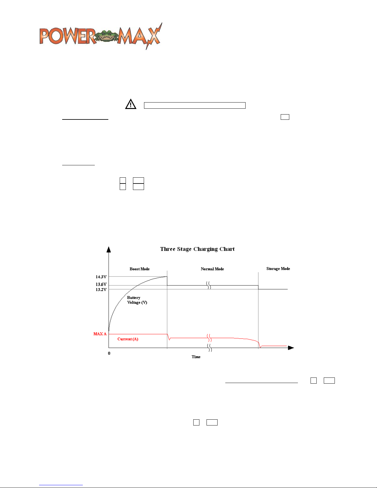
6. 3 STAGE CHARGING OPTION DESCRIPTION. This optional system provides an automatic charging system in three steps. 1.
A fast charge to bring a good, drained battery back up to full voltage rapidly ("Boost"). 2. A standard charge to bring the battery
up to a full charge at a safe rate to prolong the life of the battery and provide power to run 12V lighting and appliances in the
vehicle/device ("Normal"). 3. A trickle charge to keep the battery fresh during times of load inactivity ("Storage"). The charger
automatically changes modes to accommodate changes in conditions. The chart below is for reference only, voltages may vary.
7. TEST. First, disconnect all loads and battery on the Converter/Charger by removing all 12 VDC connections from + or POS .
Second, attach a multimeter instrument between the positive and negative terminals of the Converter/Charger. Then energize
the 120 VAC converter/charger circuit. T est for proper output power using the m ultimeter. Measure the output voltage from the
positive and negative terminals. The voltage should read 13.6 +/- 0.2 VDC. Add 12 VDC load connections to about 2/3 of the
rated capacity of the converter/charger. Recheck the voltage, which should remain approximately the same as at no load.
8. BATTERY. With th e 120 VAC disconnected, reconnect the + or POS positive terminal to a known good battery. With the
converter/charger 120 VAC energized, measure the voltage at the converter/charger and at t he batt ery. The volt age should be
about the same in both locations. As with any battery it is important that the fluid level be checked on a regular basis. When
continuously connected to any charging source all batteries will “Gas” and lose some fluid.
Copyright© 2011, Fieldstone Products Inc. Fieldstone Products Inc. reserves the right to make changes in the product at any time,
without notification. pamx-pm3-manual 19 October 2015
 Loading...