

PowerMax OV 140 P Series, 140 Series, 155x Series, OV 140 CP, SS 140 P Installation And Servicing Instructions
...Page 1
Publication No. P443 - 12/05
BAXI POTTERTON
BROWNEDGE ROAD
BAMBER BRIDGE
PRESTON PR5 6SN
(Technical Helpline) TEL 0870 606 0955
(Service) TEL 0870 606 0933 FAX 0870 606 0966
(Spares) TEL 0870 6060454
“Powermax” is a trademark of Baxi Group Ltd
The code of practice for the installation, commissioning
& servicing of central heating systems
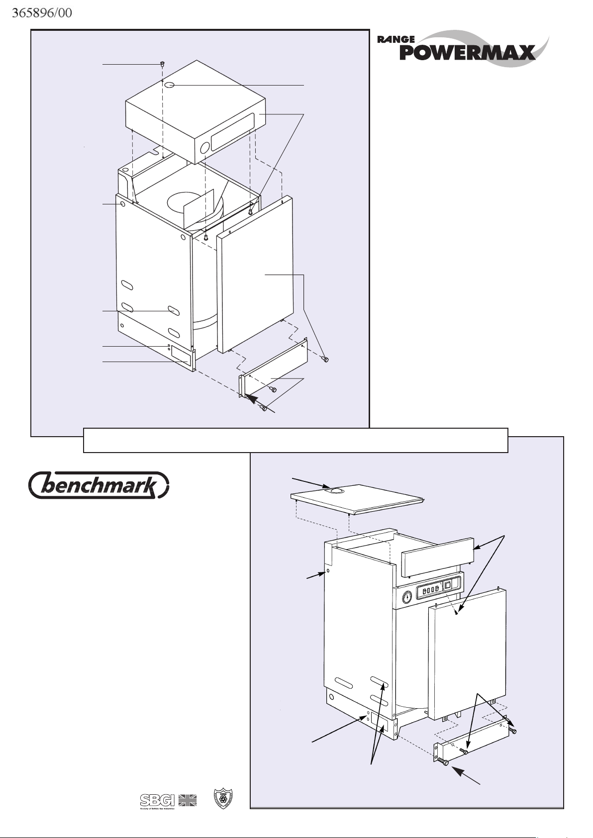
Guide to Panel Removal
Auto vent access
Main power supply
cable entry
Upper front panel and
retaining screw
Lower front panel
(2 screws)
Lifting and plumbing
access each side
External controls
cable entry
Top panel
Plinth (4 screws)
MAIN POWER SUPPLY
CABLE ENTRY
TRANSIT SCREW
EXTERNAL CONTROLS
(AND IMMERSION
HEATER CABLE ENTRY)
PLUMBING ACCESS
EACH SIDE
LIFTING AND PLUMBING
ACCESS EACH SIDE
AUTO VENT ACCESS
TOP PANEL
(2 SCREWS)
FRONT PANEL
(2 SCREWS)
PLINTH
(4 SCREWS)
Guide to panel removal
140
155
xx
Page 2

SAFETY NOTICE
In your own interest and that of safety, it is the law that all gas appliances
are installed and serviced by competent persons in accordance with Gas
Safety (Installation and Use) Regulations 1998. This appliance requires
annual checking or servicing and this should be entrusted to a CORGI
Registered Installer. All CORGI Registered Installers carry a CORGI ID
card and have a registration number. Both should be recorded in your
central heating log book. You can check your installer is CORGI
registered by calling 01256 372300.
INSTALLATION AND SERVICING
INSTRUCTIONS
TO BE LEFT WITH BOILER - READ THESE INSTRUCTIONS BEFORE INSTALLING OR
LIGHTING THE BOILER
The code of practice for the installation, commissioning
& servicing of central heating systems
140 and 155
xx
POWERMAX OPEN VENT MODELS :
OV 140 P OV 155x P WITH FITTED PUMP
OV 140 CP OV 155x CP WITH FITTED PUMP & PROGRAMMER
POWERMAX SEALED SYSTEM MODELS :
SS 140 P SS 155x P WITH FITTED PUMP
SS 140 CP SS 155x CP WITH FITTED PUMP & PROGRAMMER
Page 3

2
THIS APPLIANCE IS FOR USE WITH NATURAL GAS ONLY.
Contents
Section Page
1. Safety Regulations 2
2. Description 2-3
3. Natural Gas Supply 3
4. Electric Supply 3
5. Siting the Appliance 3-4
6. Flueing Options 4-5
7. Ventilation Requirements 6
8. Technical Data 6
9. Installing the Appliance 6-7
10. Electrical Connection to the Appliance 8
Wiring Diagrams 9
11. Water Supply / Primary System 10-11
12. Commissioning 14-15
13. Servicing Instructions 16-18
14. Fault Finding 12
15. Functional Flow Diagrams 13
16. Short List of Spare Parts 19
17. Installing an Extended Balanced Flue 20-21
18. List of Extended Flue Components 22
19. Optional Immersion Heater 23
This appliance must be installed by a competent person in accordance with
the Gas Safety Regulations and these instructions. Installers must be CORGI
Registered. Failure to install appliances correctly could lead to prosecution.
This appliance must be installed in accordance with the relevant requirements
of the current Gas Safety (Installation and Use) Regulations 1998, Local
Building Regulations, Building Standards (Scotland) Regulations, Current IEE
Wiring Regulations Health and Safety Document No. 635 “The Electricity at
Work Regulations 1989” and the Byelaws of the Local Water Undertaking.
The installation must also comply with the relevant recommendations of the
following British Standards:
Baxi supports the Benchmark initiative and the aims of the programme.
Benchmark has been introduced to improve the standards of installation and
commissioning of central heating systems in the UK and to encourage the
regular servicing of all central heating systems to ensure safety and efficiency.
1. SAFETY REGULATIONS
POWERMAX –
HIGH PERFORMANCE HOT WATER AND HEATING
Installation and Servicing Instructions
Powermax 140 and 155x are combination boilers
in which the gas burner heats the contents of a
built-in thermal store. This heated water is used
as ‘primary’ water and circulated, as required, to
the radiators. Domestic hot water (‘secondary’
water) is heated by a heat exchanger and
delivered via a thermostatic blending valve which
prevents the hot water exceeding 60°C. The flow
rate is governed to a maximum of 12 litres per
minute (140) and 18 litres per min (155
x.
A fully pre-mixed burner is used to ensure that
the gas is burned cleanly and efficiently. Ignition
is fully automatic and the ignition controller
incorporates a flame safety device.
A small diameter twin pipe flue system has been
designed for a length of up to 9.0 metres
(including a balanced flue terminal) through which
to draw inlet air and expel exhaust gases.
The standard terminal suits a wall thickness of
200mm to 500mm.
The appliance thermostat maintains the thermal
store at about 80°C and this stored water is
circulated through radiators via a pump inside the
casing.
A cold start thermostat prevents the pump from
operating until working temperature (approx.
60°C) is attained.
For summer operation the central heating can be
switched off by the user.
CP models come fitted with both CH pump and
an electronic 7-day, 3-event programmer.
Provision is made for fitting both room and frost
thermostats if required.
Installation of Sealed System models only may
fall within the scope of the Building Regulations
1992 (Part G). These require that installation of
an ‘unvented’ system shall only be carried out by
a competent person as defined in the Approved
Document G3. The above requirements do not
apply to a Powermax installed as part of an open
vented system.
Take particular care to avoid damaging outer
panels, switches, programmer etc. Trucking must
be done from the rear.
Store the appliance under cover in dry conditions.
Handling and Storage
Operation
2. DESCRIPTION
BS6891:1988
Specification for low pressure gas
pipework in domestic premises
BS5440:Part 1:1999
Specification for installation of flues
BS5440:Part 2:2000
Specification for installation of
ventilation for gas appliances (except
that compartment ventilation is
amended as in section 7 of these
Instructions).
BS5546:1990
Specification for installation of gas hot
water supplies
BS5449:1990
Specification for forced circulation hot
water central heating systems
BS6798:1987
Specification for installation of gas
fired hot water boilers of rated input
not exceeding 60kW
Page 4
3
These boilers require a natural gas supply of 1.6 to 2.0 cubic
metres per hour. Gas supply pipework of not less than 22mm
diameter should be run to the appliance and to within 300mm of
the gas valve (gascock) and should be installed in
accordance with BS6891:1988. (i.e. The pressure drop
between meter and appliance not to exceed 1mbar).
The gas connection to the appliance is Rp
1
/2 (1/2 in B.S.P.) Entry
holes are provided through the controls chassis.
The complete installation must be tested for soundness and
purged as described in the above standard and in accordance
with Corgi recommendations.
The appliance requires a 230V ~ 50Hz single phase 3A fused
electrical supply which must be installed in accordance with the
current IEE Wiring Regulations and any Local Regulations
which apply. Detailed wiring instructions are given in Section 10.
Power consumption is approximately 140W for the appliance,
with the Central heating pump rated at an additional 40W to
88W depending upon pump speed.
WARNING : THIS APPLIANCE MUST BE EARTHED
Note: This appliance may be installed in any room or internal
space, although particular attention is drawn to the
requirements of the current IEE Wiring Regulations, and in
Scotland, the electrical provisions of the Building Regulations
with respect to the installation of the appliance in a room or
internal space containing a bath or shower. Where a roomsealed appliance is installed in a room containing a bath or
shower, any electrical switch or appliance control, utilising
mains electricity should be so situated that it cannot be touched
by a person using the bath or shower.
4. ELECTRIC SUPPLY
3. NATURAL GAS SUPPLY
The appliance must be installed on a flat floor capable of
supporting the weight of the unit when full of water – up to
185kg. It should be sited to minimise the length of flue and to
avoid long hot water pipe runs.
The extended flueing capability enables the appliance to be
sited well away from an outside wall, thus installation in a first
floor cupboard or compartment, basement, utility room or
kitchen are all feasible locations. The appliance must not be
sited outside or in any outhouse where it could be exposed to
the weather.
The location chosen must permit the provision of a satisfactory
external flue termination. The location must also provide
adequate space for servicing and air circulation.
If floor settlement is likely due to the weight of the appliance,
ensure that pipework design is able to accommodate this.
When using an extended flue system it is essential to fit
protective ducting (such as that supplied in the extended flue
kits) in order to prevent direct contact with the hot flue pipe.
General requirements for cupboard/compartment installations,
including airing cupboards, are given in BS6798. Specific
requirements for Powermax installations are given below.
a The compartment must be ventilated at high and low
level in accordance with BS5440:Part 2 and Section 7
of these instructions.
b The compartment shall be a fixed rigid structure large
enough to allow it and the boiler to be inspected and
serviced. A minimum width between the door jambs of
550mm (21in) must be provided.
c Internal surfaces should be non-combustible or lined
with non-combustible material. Examples of noncombustible materials having a fire resistance of not
less than 0.5 hour are plaster skimmed plasterboard,
and fireproof boarding. The floor need not be lined.
Doors or shelves made from combustible material, e.g.
wood must be at least 75mm from the front or top of
the boiler.
d The door of an understairs cupboard shall have a
BS476:Part 8 fire resistance of not less than 0.5 hour;
and air vents must be direct to outside air.
e The flue pipe must be protected by the ducting supplied
by Baxi UK or by another no less suitable noncombustible enclosure.
f Householders should be discouraged from storing
clothes etc on the boiler itself. A removable shelf at
least 75mm above the boiler is acceptable.
Detailed recommendations for flueing are given in
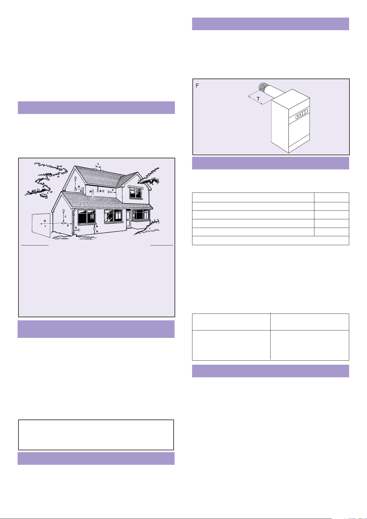
BS5440:Part 1. The following notes are intended to give general
guidance. The appliance must be installed so that the flue
terminal is exposed to the external air, preferably on a clear
expanse of wall. Acceptable positions are indicated in Fig.5.1.
Avoid positions where the terminal is adjacent to projections;
particularly immediately under a balcony, inside a re-entrant
position, or immediately adjacent to a drain pipe.
If the appliance is fitted under a ventilator or opening window,
the terminal must be at least 300mm (12in) from any part of the
window or ventilator, and in accordance with BS5440:Part 1.
Requirements for horizontal
balanced flue terminations
Compartment Installation
Flue Protection
General
5. SITING THE APPLIANCE
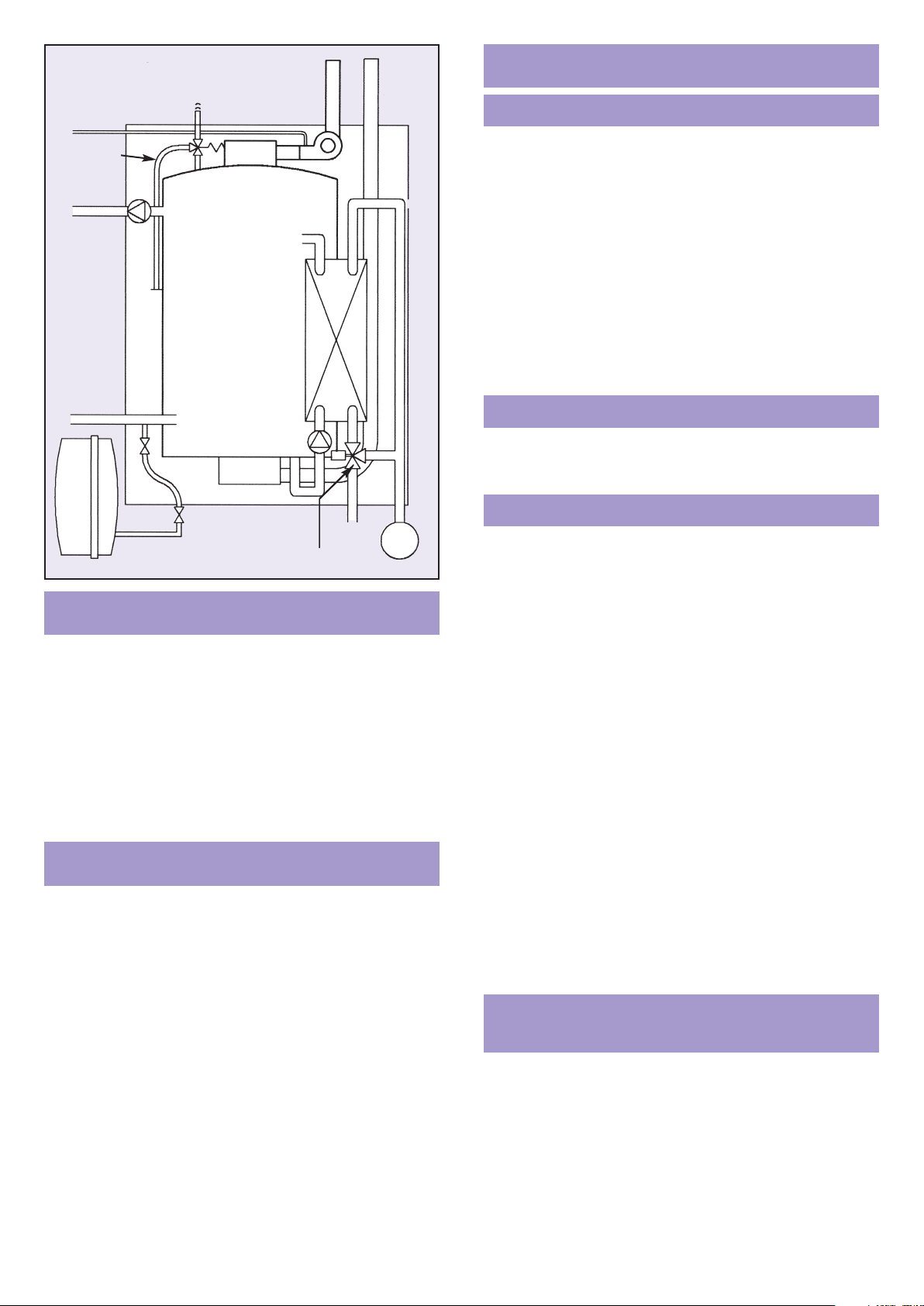
Powermax
Sealed System
Schematic
AIR VENT
PRESSURE
RELIEF
CH FLOW
CH RETURN
GAS
CH
FLOW
CH
RETURN
FLUECOMBUSTION AIR
BLENDING VALVE DHW
COLD MAIN
Page 5
4
Where the lowest part of the terminal is less than 2m (6ft) above
the level of any ground, balcony, flat roof or place to which
people have access, the terminal must be protected by a guard
of durable material. A Terminal Guard Kit is available as an
optional extra Part No. P210 from Baxi UK. The guard requires
a flat wall surface of approximately 450mm diameter,concentric
with the terminal assembly.
The exhaust flue pipe of the terminal must not be closer than
25mm(1in) to combustible material. Additional clearance must
be provided when passing the flue through timber walls.
Advice on gas installations in timber framed buildings is
contained in an IGE technical publication available from the
Institution of Gas Engineers, 21 Portland Place, London W1N 2AF.
Several flueing systems are available. ALL are ‘room sealed’
and a choice of terminals is offered:
1. Horizontal balanced flue terminal.
2. Vertical balanced flue terminal.
3. Ridge tile terminal (unbalanced)
4. Mini terminal balanced flue systems
All terminals can be sited up to 7.0m from the boiler. In some
circumstances, a horizontal terminal can be sited 9.0m from the
boiler – See below. Flue systems are supplied in kits, or
components can be ordered individually-see list in section 17.
Before starting an installation, check that the correct flue
kit has been supplied with the boiler.
The efficient operation of Powermax will naturally give rise to
condensation in the flue gases and pluming will be visible
during adverse atmospheric conditions. In installations with long
flue runs some condensate may be discharged from the
terminal. The terminal must, therefore, be sited to avoid
nuisance from either phenomenon.
Visible Pluming
6. FLUEING OPTIONS
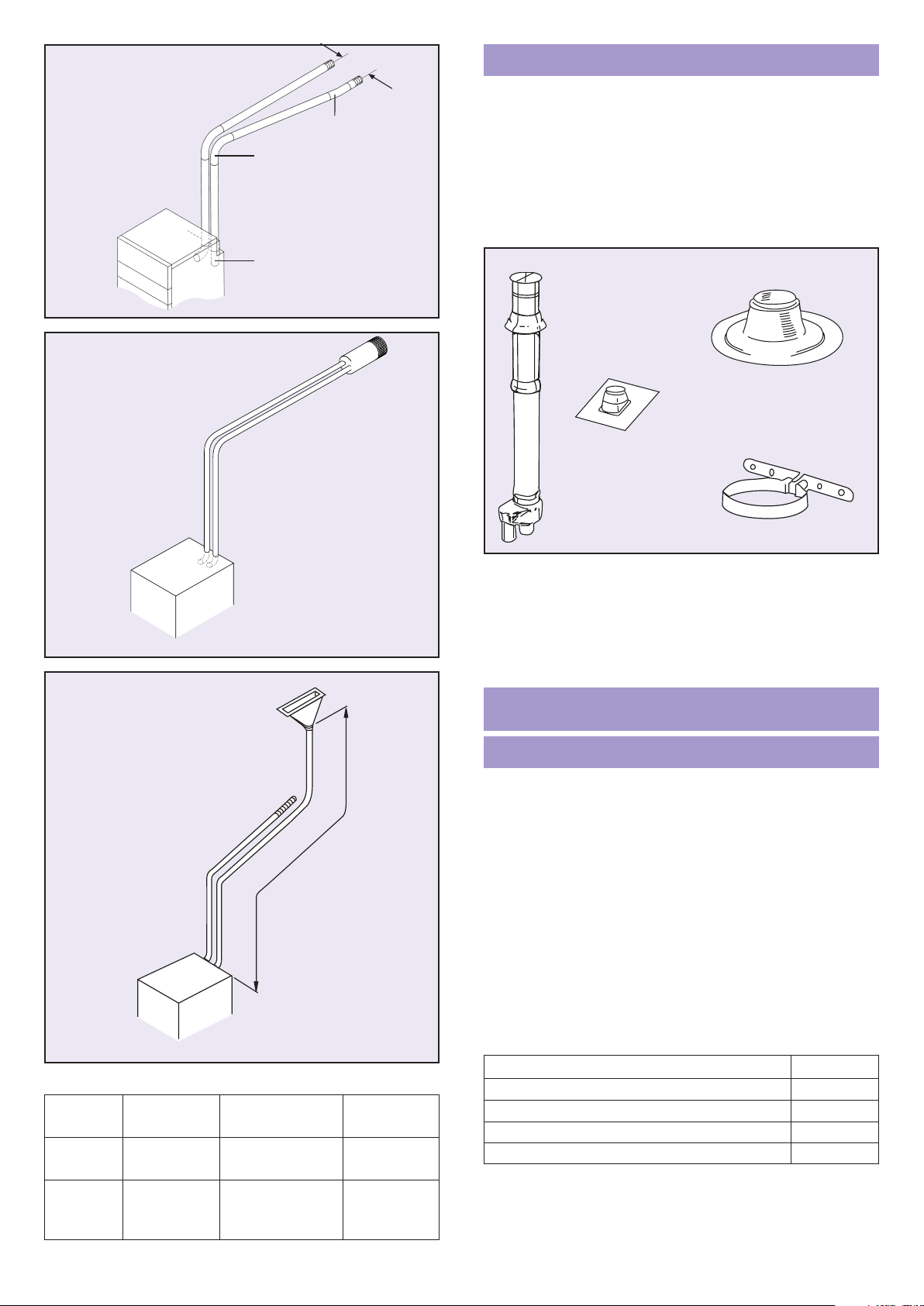
Use Kit P260 for installations where the flue passes through the
wall immediately behind the appliance. The terminal is suitable
for a thickness of 200mm to 500mm as shown in Fig.6.1.
An 800mm wall liner P337 can be ordered separately.
Step-by-step instructions are given in Section 9.
Kits are supplied as follows with components also available
separately.
Kit No.
The maximum length of each air/flue pipe must not exceed 5m
(including a Horizontal BF Terminal) when the maximum of 4 air
pipe bends and 3 flue pipe bends is used – see Fig 6.3.
The pipes can leave the boiler horizontally to right or left, or
rearwards, or vertically upwards.
There is no minimum length.
If fewer bends are used between the appliance and the flue
terminal, the maximum length of straight pipe can be increased
if required – see table below.
Kit P242 allows the flue to terminate at an approved (gas vent)
Ridge Tile Terminal with combustion air being drawn from a
ventilated loft space or from a second ridge terminal. The inlet
terminal must be not less than 300mm above the top surface of
the ceiling insulation.The air inlet pipework must be at least
1.5m long and not less than half the flue length. Full fixing
instructions are supplied in each kit.
Additional components may be specified up to the maximum
indicated in the diagram and the table opposite.
Combustion air may be drawn from a ventilated roof space or
from a compartment or duct which is permanently ventilated
direct to outside air. The effective open area of the vent must
not be less than 160cm
2
(25in2).
When combustion air is drawn from a roof space or
compartment or duct, that area must be effectively sealed from
the remainder of the dwelling. A tight fitting trap door or similar
is acceptable.
Ridge Tile Terminal
Fig. 6.5
Extended Balanced Flue Systems
Fig. 6.3
Balanced Flue Terminal
1m Sideways horizontal balanced flue P261
3m Extended horizontal balanced flue P263
5m Extended horizontal balanced flue P265
7m Extended horizontal balanced flue P267
9m Extended horizontal balanced flue P269
Refer to Section 17 for step-by-step fixing instructions.
MAX. No OF BENDS MAXIMUM PIPE
(90° OR 135°) LENGTH
Air Inlet Exhaust Flue Total Air/Flue inc. Horizontal Trml.
4 3 7 5.0m each
3 2 5 7.0m each
2 1 3 9.0m each
Lagging is recommended when the flue pipe exceeds 3m. The
insulation used must be non-combustible and suitable for
operating at temperatures up to 200°C. Class ‘O’ foil backed
glass wool or mineral wool insulation wrapped tightly around
the flue pipe will help to reduce pluming. It is not necessary to
insulate the air inlet pipes.
Flue Pipe Insulation
Fig. 6.1
‘T’ WALL THICKNESS =
200mm MIN
500mm MAX
Terminal position Min. distance
A: Directly below an openable window or other opening, e.g. an air brick 300mm
B: Below gutters, soil pipes or drain pipes 75mm
C: Below eaves 200mm
D: Below balconies or car port roof (not illustrated) 200mm
E: From vertical drain pipes and soil pipes 75mm
F: From internal or external corners 300mm
G: Above ground or balcony level 300mm
H: From a surface facing a terminal 600mm
I: From a terminal facing a terminal, or from an opening in a car port into 1200mm
dwelling (not illustrated) 1500mm
J: Vertically from a terminal on the same wall 300mm
K: Horizontally from a terminal on the same wall 300mm
L: Between ridge terminals (if combustion air is drawn from second terminal) 300mm
M: Between vertical terminal and wall 300mm
NB: Terminals located less than 2m above ground level must be protected by a terminal
guard P210
Fig. 5.1
J
IMPORTANT Any flue pipework in a horizontal plane
MUST run downwards AWAY from the boiler by 5mm
per metre. To prevent water accumulation there must
be no sags or dips in the pipework.
6
Page 6
5
Fig. 6.2
Mini terminal
flue system
Example of rearwards
flueing to achieve
minimum 300mm
distance between
terminals
Maximum permitted flue run
of 9.0m total length (including
one 90° bend and one 170°
offset Bend in the flue pipe).
Fig. 6.3
Typical routeing of
extended balanced flue
Fig. 6.5
Typical routeing of
ridge terminal flue kit
Note that
the length of
the air inlet
pipe must not
be less than
0.5 x length
of flue pipe
1.5 TO 4.0 METRES
1.5 TO 5.0 METRES
[STANDARD KIT]
1.5 TO 7.0 METRES
[EXTENDED]
Vertical RS Flue System
The Powermax Vertical RS flue system offers an unobtrusive
balanced flue terminal as an option for both pitched and flat roofs.
The vertical roof terminal Part No. P230 provides a combined air
intake and combustion gas outlet in a concentric arrangement.
Below the roof the terminal changes into a twin pipe system.
Separate roof flashing units should be ordered (specified) for
pitched or flat roofs. Roof pitches from 15° to 55° are catered for
by selecting one of three pitched roof flashing units.
P231 for pitches 15° to 25° P232 for pitches 25° to 45°
P233 for pitches 35° to 55° P236 for flat roofs
To connect the Powermax to the vertical terminal a kit Part No.
P246 is required. This contains a range of extension air/flue
pipes and bends to enable the terminal to be sited up to 2.5m
from the appliance. The maximum overall length of the
complete flue system must not exceed the limits indicated for
extended balanced flue systems, however the length of the
vertical terminal itself can be disregarded. Complete fixing
instructions are provided in each kit.
The Mini Terminal Flue system provides an alternative
arrangement to the standard (140mm diameter) balanced flue
terminal.
Separate 65mm diameter air inlet and flue terminal assemblies
can be positioned in different locations on the same wall subject
to similar wind conditions. See Fig. 6.2.
They are available in a small range of colours chosen for their
compatibility with typical external building materials.
Code.
A Matt Black
(standard finish)
D Red Brick
B Stone
(also suitable for yellow stock brick)
E Slate
C Light Brick F White
Each terminal requires a hole of 65mm diameter to be core
drilled through the external wall.
Flue kits are available as listed below. Each kit contains all the
components needed for a complete system including full fixing
instructions.
Kit No.
* For sideways flueing
WARNING – The flue pipe becomes very hot when appliance
is working. Householders should be warned not to touch
exposed pipe e.g. beyond protective duct within loft.
The flue pipe should be insulated or ducted if accidental
contact is likely.
Description
MINI TERMINAL FLUE
P231/232/233
P230
P236
P234
Fig.6.6 VERTICAL FLUE COMPONENTS
FLUEING RESTRICTIONS – RIDGE TILE TERMINAL
Number of Bends Pipe Length
Application Components 90° or 135° (metres)
Standard Air Inlet 2 1.5 minimum
Kit Flue 3 1.5 minimum
Extended Air Inlet 2-3 1.5 to 4.0
Inlet & Flue 3 max 1.5 to 7.0
Flue
1m Mini Terminal BF kit* P271
3m Mini Terminal BF kit P273
5m Mini Terminal BF kit P275
7m Mini Terminal BF kit P277
9m Mini Terminal BF kit P279
300
170 OFFSET
BEND P320
90 BENDS
P358
SHORT EXTENSION
P338
Page 7

MINIMUM EFFECTIVE AREA OF
COMPARTMENT AIR VENTS 140 155
xx
Position of opening Ventilated to Area of each vent
High and Low Level Room 54cm
2
60cm
2
High and Low Level Outside 27cm
2
30cm
2
6
7. VENTILATION REQUIREMENTS
a When the appliance is installed in a room or habitable
internal space, there are no specific ventilation requirements.
b When the appliance is installed in a compartment it is
essential that permanent high and low vents are provided for
the circulation of cooling air. Purpose made vents must have
a non-adjustable free area not less than the minimums
specified in the table below.
8. TECHNICAL DATA
Guidance on where to locate the appliance is given in Sections
5, 6 and 7. In some instances it will be advantageous to
pre-plumb pipework or to pre-fix terminal, air/flue pipes and duct.
1. Move appliance to where it is accessible for flue
preparation. For a guide to removing panels, see back
page. Remove 2 screws at bottom of front cover, pull
forward from bottom, gently ease downwards to free
location studs.
140: The lid is retained by 3 screws, 2 in the front edge under
the timer control panel and a third transit screw in the
back of the lid. The lid can be eased upwards from the
rear and pulled gently forwards and away from the
control panel. The transit screw can be discarded if
access is restricted.
155x: Remove recessed screw at top of switch panel and keep
safe. Lift off upper front cover. The top panel is retained
by 4 studs: gently ease upwards to remove. The plinth
cover is retained with 4 screws and 2 screws retain the
rear section.
2. Carefully set aside the outer covers. Remove small
press-out panel(s) either side of casing for plumbing
connection (and flue/air pipes) as necessary. The hand
hold cut outs in the side panels also provide convenient
plumbing access. The cut out in the base allows
pipework to be brought up from floor level, see Plumbing
Guide on page 23, but the pipes must not obstruct
service access to the sump. See Fig. 11.1.
3. Connect one end of electricity supply cable to the user
terminal in accordance with sections 4 and 10. The cable
must be routed via the anchorage and through the
bushing in LH side panel. See Fig. 9.6.
4. Flueing
If installing boiler with vertical RS balanced flue see
separate instructions supplied with vertical flue kit.
If installing boiler with an extended horizontal balanced
flue go to Section 17 of these instructions.
If installing boiler with a Ridge Tile Terminal or Mini
Terminals, see separate instructions supplied with each kit.
The standard flue kit P260 contains the following
components, See Fig.9.2
1 x flue terminal assembly. complete with sealing ring
1 x wall liner
1 x flexible duct AIR INLET ONLY
2 x worm drive clips
Note: The flue terminal assembly MUST be installed
horizontally.
The unit is floor standing and a vertical flat area of wall is
required 1100mm or 1260mm high x 550mm wide. If unit
is being raised above floor level, allow for this in marking
position of flue liner.
4a Mark off the centre of the 140mm (5
1
/2 in) diameter hole
as shown in Fig.9.3 and core drill.
If the wall is clad with a combustible material a 25mm
(1in) wide area around the flue liner must be removed.
Measure the wall thickness and cut the liner to this
length.Cut opposite end to lugs.
b Fit the liner through the 140mm (5
1
/2in) diameter hole
(lugs inside) and cement into position, making good
internal and external rendering. The latter may be done
with arm extended through the liner.
c Insert 50mm diameter 90° elbow into flue socket
(vertically rising pipe at the back of the appliance)
9. INSTALLING THE APPLIANCE
140 155x
Nominal Output, kW gross 14.0 16.4
Nominal Input, kW gross 17.1 20.0
Category I2H Gas G 20
Supply Pressure, mbar 20
Gas Rate m
3
/hr 1.6 2.0
Gas Connection Rc 1/2
Air sense/burner pressure
differential -
–
0.13 ± 0.03mbar.
This is factory set and no
adjustment is intended
NOx < 40 ppm – Class 5
CO < 20 ppm
Thermal store capacity 80 100
(primary water) litres
DHW Temperature °C 55-60 maximum
DHW Flow Rate, litres per 12 18
minute (maximum)
Working Pressures, bar:
Primary SS models 3 max (Design pressure
2.5 to comply with UK
Water Regulations)
Primary OV models 1.0 maximum
DHW 6.0 maximum
DHW 1.5 minimum
Pressure Relief Valve, bar: 3.0
Weight (empty) kg 75 85
Weight (full) kg 155 185
Connections:
CH Flow/Return 22mm Compression
DHW Inlet/Outlet 22mm Compression
Gas Rc 1/2
Pressure Relief 15mm Tube
(1/2 x 3/4 Tundish
supplied loose)
Electricity Supply: 230V ~ 3A fused supply
Cable Entry Top rear of LH panel
Dimensions, mm
Height 1100 1260
Width 540
Depth 600
Clearance requirements for
installation and servicing:
Top 400mm (16 inches)
Sides 5mm (10mm (3/8") total)
Base and back Nil
Front 450mm (18 in) unless
behind an openable door
Flueing:
Flue Types C13 C33 C53
(As flue kit specified)
Bal. Flue Terminal 140mm Diameter
Mini Flue 65mm Diameter
Flue/Air Pipes 51mm Diameter
Standard Flue Length 500mm
Extended Flues Refer to Section 6
(including packaging)
Page 8
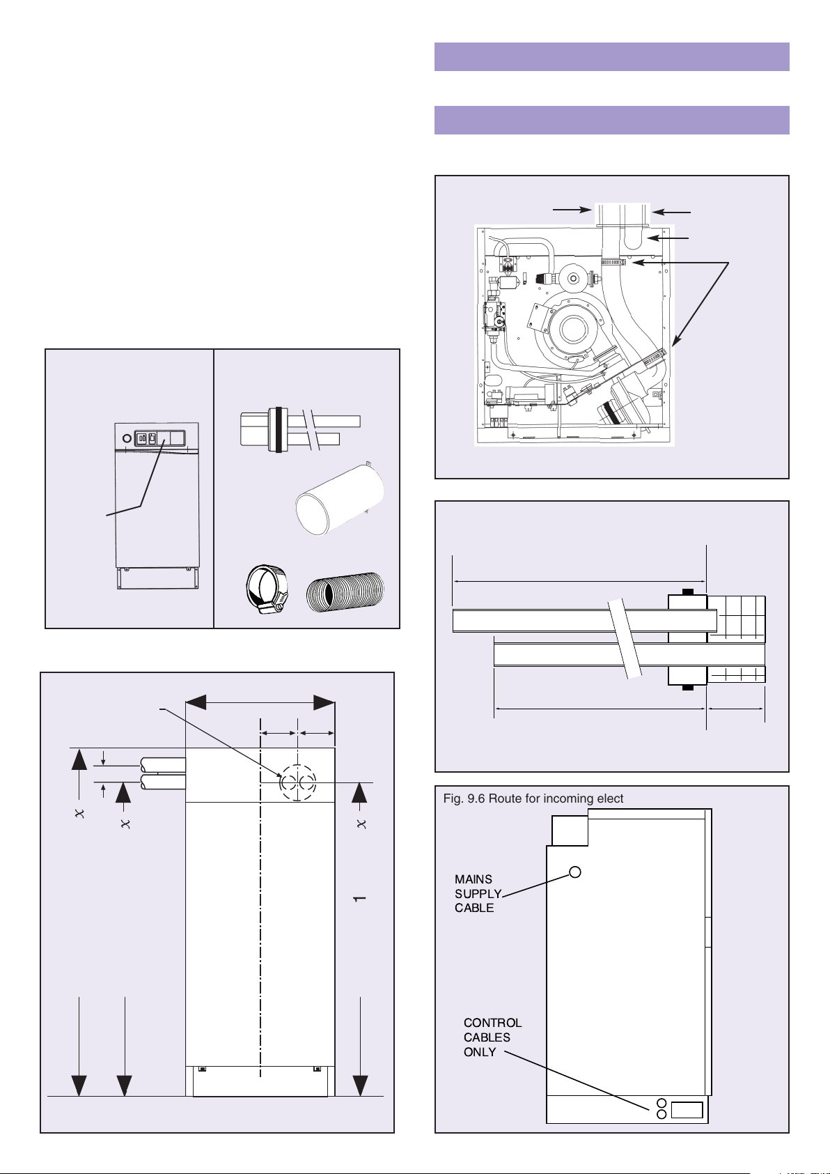
Fig. 9.3 View on front of boiler
* Normal dimensions - check actual height on appliance.
Allow also for floor unevenness.
7
Fig. 9.1
Fig. 9.2
Flue terminal assembly
Flue liner
Inlet duct
Worm drive clip
Fig. 9.4
Fig. 9.5 Flue terminal assembly
Fig. 9.6 Route for incoming electric cables
Refer to page 23 for detailed wiring instructions.
Optional immersion heater
Refer to Guide diagram on page 23. This can be ordered as a
full-size template Part No P3281.
First Fix Plumbing
AIR INLET
140 TOP
RETAINING
SCREWS
(ACCESSIBLE
AFTER
REMOVING
FRONT)
155x PANEL
RETAINING
SCREW
d Measure and cut flue pipes with a hacksaw to a length
as illustrated in fig 9.5. Measure the wall thickness and
add 10mm to the flue pipe and 120mm to the air inlet
pipe from datums ‘AA’. Remove any burrs from cut ends
of tubes.
Note: If wall is not truly vertical or appliance is
prevented from standing against wall, add stand off
distance to wall thickness measurement.
e
Push fully home ensuring inlet air pipe enters flexible
duct and exhaust flue pipe engages socket. Secure inlet
pipe with worm drive clip (See Fig.9.4).
f Carefully push appliance into position, entering terminal
into wall liner. If necessary, fit terminal guard.
5. Make gas connection as described in Section 3.
6. Fix feed and expansion cistern or expansion vessel and
make water connections as described in Section 11.
7. Test gas pipework for gas soundness in accordance with
BS6891 and latest CORGI codes of practice.
TRANSIT SCREW
WALL LINER
FLUE ELBOW
WORM
DRIVE
CLIPS
Std. Balanced Fue
540
135
135
WALL THICKNESS+120mm*
INLET
EXHAUST
WALL THICKNESS+10mm*
*(+ ANY STAND-OFF DISTANCE
BETWEEN APPLIANCE AND WALL)
'A' 'A'
83
)
N
1100(140) 1260(155
)
63
N
948(140) 1123(155
)
N
948(140) 1135(155
Page 9

8
Wiring must comply with the current IEE Wiring Regulations.
The supply cable must be 3-core 0.75sq.mm (24/0.2mm) to
BS6500 Table 16.
The supply must be of 230V ~ 50Hz. A 3A fused double pole
isolating switch may be used, having a minimum contact
separation of 3mm in both poles, providing it serves only the
boiler and its system controls. Alternatively a 3A 3 pin fused
plug may be used.
Wiring diagrams are shown in Fig 10.1 for standard model and
Fig 10.2 for model with built-in programmer. Note that the water
level switch is omitted on open vented models.
1. Connect the incoming
electricity supply
cable to terminals
L – brown
N – blue
- green-yellow
of the user terminal
block. Ensure that the
cable is routed via the
anchorage and through
bushing in LH side panel. See Fig. 9.6. Trim all excess
length from main supply cable.
2. Connect any external control cable to the terminal block
as indicated and described below – See Fig 10.4 – and
route via unused grommets on lower LH side of unit.
Note. The length of the conductors between the cord
anchorage and the terminals must be such that the
current carrying conductors become taut before the
earth conductor if the cable is tugged, ie the earth wire
must be longer than both the live and neutral when
connecting into the terminal block.
3. To wire a room thermostat, remove orange link wire from
terminals 27 and 28. Connect the feed wire to the stat to
terminal 27, connect the switched wire to terminal 28
and the neutral to N3.
4a. To provide time to control for models without the built-in
programmer, we recommend using the Powermax
‘Diadem’ analogue programmer kit P4230. To install
remove the slave plug – see Fig 12.2 – and replace with
the plug-and-lead supplied. Fixing instructions for the
‘Diadem’ programmer are supplied in the kit.
4b. Alternatively choose a twin channel programmer that has
volt free contacts, as provided by programmers which
use the British Gas standard wall plate configuration and
a pumped/gravity option which should be set to “gravity”.
See Fig. 10.3. Power the programmer from terminal L2
and link to one side of the programmer’s hot water relay
contacts. Connect the switched hot water contact to
terminal 24. To wire the central heating channel, remove
link wire (terminals 27 and 28) and connect the
programmer’s CH relay contacts to terminals 27 and 28.
NB The appliance switch must be kept in the OFF
position otherwise the DHW remains permanently
switched on. The central heating switch should be ON to
obtain timed switching.
5. If a combined clock thermostat is being used to control
the central heating, it should be of a type having voltage
free contacts. Remove link wire (terminals 27 and 28)
and connect the switched wire to terminal 28, feed wire
to terminal 27.
A permanent live is available at terminal L2 and
additional neutral at terminal N3 for supplying power to
the clock.
10. ELECTRICAL CONNECTION
TO THE APPLIANCE
6. If a frost ‘stat is required, this should have voltage free
contacts and provide a single pole double outlet.
Connect as follows:
Frost ‘stat live to terminal L2
Output 1 to terminal 24
Output 2 to terminal 26
The Sopac-Jaeger TA 547-04 (Double Outlet) is a
suitable frost protection thermostat.
7. After completing the electrical connections, perform the
following electrical system safety checks:
A – EARTH CONTINUITY
B – POLARITY
C – RESISTANCE TO EARTH
D – SHORT CIRCUIT
WARNING – THIS APPLIANCE MUST BE
EARTHED
Fig. 10.4 Terminal block
Fig. 10.3
N
L
N
L
D
H
W
ON
COM
24
L1
N1
OFF
25 BR
ON
C
H
T
G
COM
N2 BL
G/Y
L2
OFF
26
27
L
N
28
N3
Page 10

9
Fig. 10.1
WHITE
GREEN
YELLOW
BLACK
RED
BLUE
Fig. 10.2
BL
Fig. 10 Powermax 140 / 155x wiring diagram
Page 11

10
It is essential that the mains water supply pressure and flow
availability are capable of meeting both the hot and cold water
services demand. The unit is capable of delivering up to 12
litres/min (140) or 18 litres/min (155x) of hot water. Where the
mains pressure is in excess of 6 bar, pressure reduction to
between 2 to 3 bar is recommended for splash free tap operation.
Unless consistently high mains pressures are available, it is
unlikely that a mains service pipe of less than 22mm OD
(copper) or 25mm OD (Blue MDPE) will provide an adequate
flow rate to the system. Powermax is not recommended for use
where the prevailing mains pressure is below 1.0 bar.
A full way isolating valve (e.g. gate valve or quarter-turn valve)
should be fitted in the supply before, but adjacent to, the unit.
It is recommended that a 22mm draw-off is provided from which
15mm or smaller pipes can then be used to supply hot water
services to individual terminations to give a balanced
distribution system.
Taps: Ensure that all terminal fittings will withstand mains
pressure.
Showers: Because of the draw-off profile, thermostatic shower
mixers are recommended to optimise performance; these must
be suitable for use at mains pressure. The Range ‘Showermax’
thermostatic shower kit is recommended for use with this boiler.
Where it is possible for a flexible shower handset to reach
below the bath spillover level, compliance with the Water
Byelaws is essential.
In areas where temporary hardness exceeds 200mg/L,
treatment of the mains water supplied to the appliance is
recommended to maintain its performance. The Powermax
electronic water conditioner P3237 is available factory fitted or
can be retro-fitted. Any scale reducer, or ion-exchange softener,
will be most effective when installed immediately upstream of
the boiler i.e. in the inlet pipework.
Good quality polyphosphate dosing devices can also inhibit
scaling but generally should not be fitted where heat could
impair their performance. Always follow the manufacturer’s
instructions.
Record the type of conditioner being used in log book.
FLOW AND RETURN CONNECTIONS
These are on the LH side of the unit; the flow is taken from
below the pump. Pipework can be run inside the casing but
must not prevent the removal of the flue collector sump –
see NO GO area in Fig. 11.1. See also the plumbing layout
Guide on page 23.
PRIMARY SYSTEM
Use in Hard Water Areas
Terminal Water Fittings
Mains Supply Requirements
11 WATER SUPPLY
Fig. 11.1 Water connections
Fig. 11.2a
!" #$"%
&"!"&
When installing ‘OV’ variants of Powermax the thermal store
within the appliance must be supplied with primary water from a
low pressure source e.g. a feed and expansion (F&E) cistern.
The unit is suitable for a maximum working head of 10 metres
(33ft head). The minimum static head is 600mm.
The vent pipe connection is situated at the top of the unit.
A 22mm open vent pipe must rise continuously, unimpeded, to
above the feed and expansion cistern. The top rear panel is cut
away to enable the vent pipe to run on the wall behind the
appliance.
Note also that the F & E water level must be at least 1metre
above the highest point of the primary circulation system.
An unvalved feed and expansion pipe must be provided from
the F & E cistern and teed into the C.H. return near the boiler.
Use 22mm if plastics pipe is used or if head is less than 1m.
Open Vented Systems
PIPEWORK ABOVE BOILER
Where the boiler has pipework rising above it, a non-return
valve should be fitted, preferably in the flow where it will not
obstruct filling.
Air vents must be fitted at the highest positions on flow and
return pipes and at any point where air is likely to collect.
TRVs IN SYSTEM
When all radiators are fitted with Thermostatic Radiator Valves,
a bypass loop (manual or automatic) must be provided.
SOLDER FLUX
Use water soluble flux for making soldered capillary joints in the
primary circuit. Traditional grease-based flux must not be used.
DISCHARGE
PIPE
CH RETURN
CH FLOW
DHW OUTLET
COLD INLET
PLUMBING
NO-GO AREA
Page 12

11
Sealed Primary Systems
Only ‘SS’ variants can be installed with a sealed primary
system. The ‘SS’ prefix is recorded on the Data Badge and
external packaging.
‘Sealed System’ models have an air separation fitting at the
back of the boiler. This also houses the water level safety switch
and connects the pressure relief valve and automatic air vent.
The installer must fit an external expansion vessel of adequate
expansion capacity. As a general guide systems of up to 7-9
radiators will need an 18 litre vessel; a 12 litre vessel may be
satisfactory for 5 radiator systems. The table below indicates
the size of vessel required for systems of different water
capacities.
For optimum performance after installation, Powermax and its
associated central heating system should be flushed in
accordance with the guidelines given in BS7593: 1992 –
Treatment of water in domestic hot water systems. Full
instructions are supplied with proprietary cleansers sold for this
purpose.
To help prevent both radiator corrosion and the possibility of
noise inside te boiler, it is recommended that Inhibitor is used.
To ensure that the correct amount of inhibitor is used add the
volume of the Powermax thermal store to your radiator and
pipework calculations as shown. It should be used in
accordance with the guidelines in the above standard and the
inhibitor manufacturer’s instructions.
Suitable inhibitors and flushing agents are available from
BetzDearbom and Fernox. Instructions for use are supplied with
these products.
Once the system has been fully flushed, complete the relevant
section in log book.
System Flushing
Fig. 11.2b
Fig. 11.3 Typical Discharge Pipe Arrangement
0
1
2
3
4
5
10 20 30 40 50 60
70
m
FLOW LITRES/MIN
PUMP PERFORMANCE AT 230V-50Hz
TEMPERATURE: 80 C
Fig. 11.5
10 20 30
120 240 360 480
20
40
60
80
100
8
16
24
32
40
PRESSURE LOSS (mbar)
PRESSURE LOSS (in. W.G.)
HYDRAULIC RESISTANCE OF THE PRIMARY STORE
FLOW (GALL/H)
FLOW (LITRES/MIN)
Fig. 11.4
Volumes in litres
Expansion Powermax Radiators Total
Vessel 140 155
x Pipework System
140 155x Volume
12 80 100 117 97
max
197 max
16 80 100 182 162 max 262 max
18 80 100 215 195 max 295 max
An 18 litre expansion vessel part No P105 and wall bracket
P116 are normally supplied with sealed system boilers.
Connect the expansion vessel to the boiler central heating
return using a 15mm pipework spur, see Fig.11.2b. This spur
can also be used to connect a WRC approved filling loop.
Observe this sequence when installing loop: mains – stopvalve
– flexible hose – double check valve – boiler primary circuit.
NB: If the stopvalve is not in sight of the pressure gauge on the
Powermax, fit an additional gauge adjacent to the filling loop.
On ‘SS’ variants a pressure relief valve set at 3.0 bar is fitted at
the top of the thermal store. A 15mm pipe from the relief valve is
accessible at the front of the boiler. The tundish (supplied loose)
may be fitted within the casing or externally. The discharge pipe
from the tundish should be not less than 22mm diameter, and
must have a continuous fall to a visible and safe position.
See Fig 11.3.
Pipework from the tundish should fall vertically for 300mm and
then continue by continuous fall to a visible safe termination –
preferably below a fixed grating and above the water seal of a
trapped gulley. The tundish must be kept clear of electrical
devices.
Under normal working conditions no discharge will occur.
A multiple fault condition could cause a short discharge of
scalding water and steam. Adequate precautions should be
taken to prevent obstruction of the outlet and to minimise the
danger to persons (especially children) and property.
Section G3 of the Building Regulations Approved Document
should be consulted for full information.
TUNDISH
300mm MIN.
DISCHARGE
ABOVE
GRATING
FIXED
GRATING
FIXED
TRAPPED GULLEY
HYDRAULIC RESISTANCE OF THE PRIMARY STORE
METAL DISCHARGE
PIPE FROM TUNDISH
WITH CONTINUOUS
FALL
FLOW (GALL/H)
18L EXPANSION VESSEL
DOUBLE CHECK VALVE
CODE No. P105
FLEXIBLE HOSE
STOP VALVE
MAINS WATER
15mm SPUR
CH RETURN
135
DUCT
190
540
380
PUMP PERFORMANCE AT 230V-50Hz
TEMPERATURE: 80 C
Page 13

YES
12
Fault finding chart
YES
APPLIANCE
SATISFACTORY
NO
DOES APPLIANCE
REMAIN RUNNING
IF STUTTERING IGNITION IS
YES
NO
IS GREEN NEON LIT
IS GAS PRESENT AT GAS VALVE
INLET PRESSURE TEST POINT
YES
NO
OBSERVED, CHECK ELECTRODE
AND CONNECTION AS IN
PREVIOUS COLUMNS.
IF SMOOTH IGNITION IS
OBSERVED BUT BURNER GOES
OUT AFTER APPROXIMATELY
3 SECONDS CHECK IGNITION
CABLE/ELECTRODE. REPLACE
AS NECESSARY.
4
)
YES
NO
CHECK GAS IS CONNECTED AND
TURNED ON. CHECK FOR
OBSTRUCTIONS IN GAS LINE.
N
) or 4.0 mbar (140)
N
5.0 (155
4.0mbar(140) or 5.0(155
IS GAS PRESENT AT GAS VALVE
OUTLET PRESSURE TEST POINT
DURING IGNITION ATTEMPT
APPROX 4.5 mbar
NO
YES
CHECK ELECTRODE AS IN
IF IGNITION CABLE AND
ELECTRODE OK THEN REPLACE
IGNITION CONTROLLER.
PREVIOUS COLUMNS. CHECK
YES
YES
NO
NO
CHECK FOR 230V AT
TERMINAL G1
ELECTRODE GAP DISTANCE
FROM BURNER FACE. IF NOT
APPROX. 13mm RECTIFY.
TURN OFF GAS AND USE
MIRROR TO CHECK FOR
STRAY HT SPARKING.
CHECK OVERHEAT STAT AND
WATER LEVEL SWITCH AND
RECTIFY FAULT, E.G. REFILL
SYSTEM.
IF OK CHECK FOR 230V AT PIN
8 (BLACKWIRE) ON THE
NO
NO
IS BOILER GAS RATE
SATISFACTORY
IGNITION CONTROLLER
CHECK FOR FAULT AT GAS
CHECK FLUE PIPES ARE
NOT BLOCKED
)mbar
N
) 3.8.4.4 (140)
N
3.8 - 4.4(140) 4.8 - 5.5(155
VALVE OR AIR SENSE LINE.
4.8.5.5 (155
CHECK FAN PRESSURE IN AIR
SENSE LINE IS BETWEEN 4.5
AND 5.2 mbar.
CHECK THAT THE FLUE PIPE
YES
NO
CHECK FAN, FLUE WAYS AND
IS CORRECTLY CONNECTED
TO TERMINAL
INJECTOR HOUSING FOR
CHECK THAT THE MAXIMUM
OBSTRUCTION AND RECTIFY.
IF SATISFACTORY CHECK COIL
LENGTH OF AIR/FLUE PIPES
AND BENDS HAS NOT
BEEN EXCEEDED
ON GAS VALVE. REPLACE
COIL/GAS VALVE AS
NECESSARY.
DOES SPARK
ELECTRODE SPARK
YES
NO
YES
IS THE RED NEON LIT
DOES THE FAN RUNNOIS THERE POWER
SWITCH OFF WAIT 10 SECS
SWITCH ON
YES
IS ORANGE NEON LITNOIS THERE 230V TO
ENSURE THAT H.T. LEAD
IS PROPERLY CONNECTED
AT CONTROLLER AND THAT
THE WHITE EARTH WIRE IS
PUSHED HOME ON THE
NO
YES
TO THE FAN
HEATING
DOES THE IGNITION
CONTROLLER GENERATE
ELECTRODE EARTH PLATE
A SPARK.
CHECK FAN CAPACITOR
AND WIRING FOR FAULT
CHECK FOR DAMAGE OR
NO
THE UNIT
NO
REMOVE THE BURNER AND
REPLACE (OR CHECK)
ELECTRODE. THE CORRECT
SPARK GAP IS 3.5/4.0mm
NO
BLOCKAGE TO THE FAN
REPLACE CAPACITOR/
REPLACE FAN
HAS THE LIMIT STAT TRIPPED
YES
CHECK CIRCUITRY TO AND
AROUND NEON. IF CORRECT
REPLACE NEON.
NO
REPLACE ELECTRODE IF FAULTY
(ADJUST ELECTRODE BY
MOVING EARTH POST ONLY).
PLACE THE ELECTRODE END OF
THE HT LEAD ON BURNER. IS A
SPARK TO THE BURNER VISIBLE?
YES
YES
TEST FOR AND RECTIFY ANY
OVERHEAT FAULT, I.E.
DEFECTIVE BOILER STAT
CHECK HEAT EXCHANGER PUMP
WORKING AND NOT AIR
CHECK FOR 230V EITHER
SIDE OF FILTER.
IF FAULTY REPLACE.
REPLACE IGNITION CONTROLLER
NO
YES
LOCKED. REPLACE IF FAULTY.
CHECK BOILER
THERMOSTAT IS CALLING
FOR HEAT.
CHECK MAINS SUPPLY
LEAD/FUSE. REPLACE AS
NECESSARY.
CHECK CIRCUITRY TO FAN
CHECK IF PROGRAMMER/HEATING
SWITCH IS CALLING FOR HEAT.
CHECK SWITCH + WIRING FOR 230V
BETWEEN SWITCH/PROGRAMMER
AND BOILER STAT.
FROM IGNITION CONTROLLER.
REMOVE IGNITION CONTROLLER
AND CHECK INTERNAL FUSE.
IF FAULTY REPLACE WITH
CORRECT 20mm FUSE,
I.E. 2A HRC
IF FUSE IS OK
REPLACE CONTROLLER.
START
THE APPLIANCE WILL NOT:
IGNITE THE BURNER
DELIVER HOT PRODUCE
WATER CENTRAL
DOES THE FLOW
YES
SWITCH OPERATE THE
HE. PUMP IE 230V AT
TERMINAL 23 WHEN THE
BURNER IS NOT LIT
) IF THE FLOW IS
N
IS THE CYLINDER UP TO
THE CORRECT
TEMPERATURE
CHECK THE BLENDER VALVE.
CHECK THE FLOW RATE IS
NOT GREATER THAN 121/MIN
IF THE FLOW IS POOR CHECK
THE INLET STRAINER AND
CHECK THE BLENDER VALVE.
INCOMING WATER SUPPLY
CHECK THE FLOW RATE IS NOT
GREATER THAN 12 L/MIN (140)
18 L/MIN (155
POOR CHECK THE INLET
STRAINER AND INCOMING
WATER SUPPLY
CHECK THE FLOW SWITCH
RELAY ASSEMBLY, REPLACE IF
CHECK THE BOILER STAT
FAULTY
YES
IS THE APPLIANCE/
PROGRAMMER/ROOMSTAT CALLING
FOR HEAT IE 230V AT TERMINAL 28
CHECK THE COLD START STAT
(DOMESTIC PRIORITY STAT) IT WILL
NOT ALLOW CENTRAL HEATING
WHEN THE CYLINDER STORE
TEMPERATURE IS BELOW 65°C
IF OK CHECK PUMP AND
CONNECTIONS AT TERMINAL
25 AND N2
Page 14

13
140 / 155x Functional Flow Diagram 1
P Model with remote programmer connected
140 / 155x Functional Flow Diagram 2
CP model with built-in programmer
NB: Water level switch is omitted on Open Vent models.
Page 15

14
a With no water pressure on the system , check and if
necessary adjust expansion vessel pressure to 0.6 to 0.7
bar (8 to 10 psi) N.B. Vessel pressure cannot be
accurately set with water pressure in system.
b Loosen cap on automatic air vent, check draincock is
closed and open isolating valves on CH pump.
c Open stopvalve(s) and fill system with water to approx.
0.9 bar. Release air from radiators and pipework and run
cylinder up to temperature with CH off.
Bleed both heat exchanger and CH pumps.
d Thoroughly check radiator valve connections, glands
and unions for leaks.
e Set CH pump to speed 3, bleed every radiator and
pipework high points until all air or air/water mix is
removed.
f Allow system to reach full temperature (boiler ‘stat
switches off) and note HOT system pressure. Check that
relief valve is not “passing” by observing tundish over
several minutes.(“Passing” is usually due to debris on
valve seat. Snapping valve shut several times will
normally cure this). After firing and checking, drain and
flush the system, refill as above adding inhibitor, and
check for leaks.
g Again bleed every radiator etc. until all air or air/water
mix is removed and re check relief valve.
h Check system final pressure equals HOT pressure noted
in f above. Top up pressure if necessary.
i Adjust CH pump to correct speed for system. Remove
flexible hose and leave in a secure position for
householder. Protect hose union threads with end caps.
a Ensure Draincock is closed.
b Open valves either side of central heating pump .
c Admit water to the F&E cistern and thence to the
thermal store and the remainder of the central heating
system. Bleed both heat exchanger and CH pumps.
d Open any radiator valves and air bleed valves so as to
ensure that the store and radiators are full.
Note: Drain and flush the system. Refill as above adding
inhibitor, and check for leaks.
a Open one or more hot water taps.
b Turn on mains water supply and observe air free water
issuing from tap(s).
c Close tap(s) and check mains water pipework for leaks.
d Check that all factory-made plumbing connections
are tight (and have not loosened in transit).
e The blending valve is pre-set to supply water at
approximately 57°C and does not require adjustment.
CHECK POLARITY OF ELECTRICAL SUPPLY IS CORRECT.
CHECK THERMOSTAT WIRING, ie ‘SWITCHED’ WIRE IS
CONNECTED TO TERMINAL 28.
Remove screw from solenoid valve inlet pressure test point
Fig.13.4 and attach a suitable gauge.
a Turn any in-line gascock ‘on’ and turn the service
gascock ‘on’.(Indicated by the screwdriver slot being in
line with the direction of gas flow.) See Fig.12.3.
Starting (Lighting) The Appliance
Domestic Hot Water System
Open Vented Primary System
Sealed Primary System
12. COMMISSIONING
WARNING: DO NOT ATTEMPT TO START THIS APPLIANCE
UNLESS THE THERMAL STORE (PRIMARY CIRCUIT) HAS
BEEN FILLED WITH WATER
Fig. 12.1
1. Pressure Test Screws
2. Air-gas Ratio Valve
3. Union Gascock
4. Ignition Controller
5. H.T. Lead
6. Ignition Electrode
7. Air Sense Tube
8. Boiler Thermostat
9. Capacitor
10. Cold Start Thermostat
11. Injector
12. Burner
13. Air Inlet Pipe
14. Flue Pipe
15. Water Level Switch
16. Auto. Air Vent
17. Safety Relief Valve
18. EMC Filter
19. User Terminal
b Switch electricity supply on at the isolating switch and
observe orange neon on control panel indicating the
mains supply is live.
Note: Switch panel layouts are shown in Fig.12.4 for standard
model and Fig.12.5 for model with built-in programmer.
c Move the appliance on-off switch to the ‘I’ (on) position
(standard model) or ‘CONT’ (programmer model). Fan
starts to rotate after a slight delay. After a few seconds
the automatic ignition sequence will be initiated and the
burner will light.
d Green neon indicates the burner is operating.
Note: If the burner fails to light, the ignition sequence will be
automatically repeated until either the burner lights or a
safety LOCK-OUT condition is signalled by the red
neon. If red neon glows, switch to ‘O’ (OFF) at the
appliance on/off switch, WAIT TEN SECONDS
BEFORE SWITCHING ON AGAIN.
e With the appliance operating check the green neon is stable.
Note: After first filling with cold water some noise may
occur within the combustion chamber as the flame
settles on the burner. This is normal and will disappear
after approximately one minute. It does not occur in
normal use.
f Run boiler for 15-20 mins and transfer manometer tube
to outlet test nipple. Check burner pressure is
approximately 3.8 to 4.4 mbar (140) or 4.8 to 5.5 mbar
(155x). NB The longer the flue system the lower will be
the expected pressure. Record operating pressure in
log book. Very low values e.g. 3.0 mbar,
indicate an obstruction in the air supply; a high pressure
e.g. >6.0 mbar indicates a blockage in the flue pipe or
sump - see fault finder chart on page 12. Note that the
gas valve is factory pre-set and the burner pressure is
not directly adjustable. In case of difficulty consult The
Technical Helpline 0870 606 0955
g Record the “working” inlet gas pressure at inlet pressure
test nipple – Fig. 13.4 – in log book.
h Turn appliance off, remove gauge, replace test screws
and test for gas soundness.
Page 16

15
Fig. 12.2
1. Relay
2. Limit Thermostat
3. Terminal Block
4. Overheat Thermostat
5. Fan
6. Appliance ON-OFF Switch
7. Neons
8. Programmer
9. Programmer ON-OFF
Switch (At back of
programmer)
10. Blending Valve
11. CH Pump
12. DHW Expansion Vessel
13. Combustion Test Point
14. Heat Ex. Pump
15. Sump
16. Remote Programmer Slave
Plug
17. Flow Switch
18. Flow Switch Relay
Fig. 12.3
a Explain the appliance controls.
b Give guidance if the system is to
be shut down for long periods
when freezing is possible.
c Advise that the appliance should
be serviced regularly.
d Explain that the correct
operating position for the 3-way
switch is the down TIMED
position which enables HOT
WATER and HEATING to be
obtained when required. The up
HOT WATER position will
provide 24 hour hot water
availability in the unlikely event
of the programmer failing.
e Explain how to re-start appliance if
red neon indicates lock-out.
f Hand over the User’s
Instructions, Installation
Instructions and completed
log book to the user.
Fig. 12.4 Standard Switch Panel
Fig. 12.5 Programmer Switch Panel
The Central Heating System
Handing Over to
the User
a On programmer model, set the 3-way-switch to
TIMED and commission the programmer by moving
the slider switch (accessible behind the switch
panel) to the right.
Press SELECT HW and SELECT CH buttons (repeat if
necessary) until the indicators align with either ALL DAY
or 24HR, Fig 12.5, and press SET button to align left
hand indicator with RUN.
On standard model move central heating switch to the ‘I’
(on) position, Fig 12.4.
b Check that any connected room thermostat is calling for
heat.
c Note that the central heating pump will not operate until
the storage cylinder contents have reached a
temperature of approximately 60°C. After filling with cold
water, this will normally take between 20 to 25 minutes.
d Wait until the thermal store has reached its normal
temperature of approx 82°C (by temporarily switching
the central heating off again) before balancing the
radiators in the usual way to achieve a temperature drop
of 10° to 15°C.
e Set the room thermostat or programmer according to the
manufacturer’s instructions. On programmer model
press SELECT CH button to align CH indicator with
AUTO and press SELECT HW button to align indicator
with ALL DAY.
f With the thermal store fully heated, check DHW output
temperature is approximately 55-60°C using nearest tap
and a flowrate of approximately 5 l/min. Record inlet and
outlet temperatures in log book.
g Measure hot water flow rate at bath tap (fully open) and
record in log book.
h Refit outer covers and plinth front in reverse order.
876 4
1
2
3
18
16
11
17
12
15
10
14
13
9
5
GAS VALVE
GAS SERVICE COCK
ON/OFF SCREW
WARNING : DISCONNECT ELECTRICITY BEFORE REMOVING COVER
! "
#
ST
"
MAINS
ORE
+
BURNER
LOCK
OUT
POWERMAX
Page 17

16
a Remove two M4 screws holding fan to burner, also air
inlet elbow retaining screws. Pull fan away from burner
and rest on ledge formed by cross brace. Disconnect air
sense tube and check that it remains supple and free
from splits etc. Release both union nuts on gas pipe.
Note: Hold injector with second 19mm AF spanner
to prevent injector being disturbed. Swing pipe clear
of burner.
b Loosen 8 screws around burner flange. Lift burner
gently upwards until ring clears the controls chassis.
Keep screws safe.
Gently remove deposits from burner face and inspect.
Renew burner flange gasket.
c Disconnect the HT lead at the electrode and check that
the connection is clean and tight. Inspect the electrode
condition and check gap which should be 3.5 to 4.0mm.
d Sealed system models only – release system pressure
via relief valve and check expansion vessel pre-charge
pressure is between 0.6 to 0.7 bar. Adjust if required
and top up system to same pressure. Remove air from
boiler via automatic air vent.
e Reassemble in reverse order ensuring all 8 burner/fan
screws are tight. Check that fan lead remains clear of
motor after re-assembly.
NB: Check tightness of burner screws again after
boiler has operated for several minutes.
Routine Annual Servicing
To ensure safe, efficient operation of the appliance, it is
necessary to carry out routine servicing at regular intervals.
The frequency of servicing will depend upon the particular
installation conditions and the use to which the boiler is put.
IMPORTANT: Before commencing any servicing or
exchange of components, always turn off the gas supply
and isolate the electricity supply.
An annual inspection is recommended with servicing every
other year.
After completing any service work always test for gas
soundness.
To gain access to the boiler for servicing, remove front panel
and top cover as described in section 9 and fig 9.1.
Note before removing any of the burner parts for servicing
ensure you have a new burner gasket P507 available.
13. SERVICING INSTRUCTIONS
Annually
Every Second Year
f Additionally to the above.
Use pliers to remove turbulators from heat exchanger
pipes. Visually inspect combustion chamber and pipes
for excess deposits (a small torch will be useful). If
cleaning is required, first remove sump – see step g.
g Remove M6 screw that secures the retaining strap and
withdraw strap. Allow sump to drop vertically to floor
level but leave underneath boiler to collect deposits.
h Heat exchanger tubes can now be cleaned using a
28mm (1
1
/8") diameter brush. Remove sump ensuring it
is clear of gauze in flue collector. Vacuum away deposits
and clean sump prior to replacing.
Note: Apply similar care when replacing sump, ensuring
it is evenly retained. Check sump joint for soundness
using an electronic ‘sniffer’ whilst boiler is operating.
i Check that boiler and its controls are functioning
correctly.
j Remove HW mini expansion vessel and probe bladder
using a blunt instrument. Replace if deflated, Part No. P527.
Fig. 13.1
Fig. 13.2
Combustion testing
A combustion analysis test point is provided on the flue
collector (just above sump joint). The test point is a tapped hole
and is sealed by a special screw/washer assembly. Insert the
sampling probe by approximately 25 to 30mm until it touches
the inner gauze. This will enable an accurate reading to be
taken. For a correctly installed appliance typical values to be
expected are:-
CO < 20ppm
CO
2
8.8 - 9.6%
Levels significantly outside these limits should be investigated
and may indicate a defective component or faulty installation.
Ensure the test point is FULLY GASTIGHT. Do not substitute
any other screw for the special Powermax screw
(Part No. P690).
Electrical safety testing
It may be necessary to carry out electrical test work to ensure
the safety of the appliance circuits after overhaul or as part of
an inspection programme. This should be carried out to latest
edition IEE regulations for Class 1 appliances with the flash test
set at 1500 volts.
140 TOP RETAINING
SCREWS
(ACCESSIBLE AFTER
REMOVING FRONT)
155x TOP PANEL
RETAINING SCREW
TRANSIT SCREW
FRONT PANEL FIXING
SCREWS
PLINTH FIXING
SCREWS
Page 18

17
Air/Gas (Solenoid) Valve Fig.12.1 & 13.4
a Refer to General above.
b Disconnect gas service cock at the union and
disconnect the outlet pipe at the union nut on flared
fitting.
c Remove screw holding bracket. Disconnect the wiring
leads and remove valve. Remove bracket.
d Remove the flared fitting from valve outlet and transfer
to new valve. Note: Threads on valve outlet must be
resealed with a sealant complying to BS5952.
e Fit new valve in reverse order. Ensure that inlet and
outlet connections are fully gas tight.
Procedure for checking/setting S.I.T. Sigma 848 Air/Gas
Ratio Valve
Do not attempt these adjustments unless you have both
the use of a correct specification of digital manometer
and the relevant training.
i Using a differential manometer connect the positive side
of the manometer to the gas valve outlet pressure
tapping and the negative side to the air pressure sense
line using a tee piece.
ii Start the boiler, ensure that the inlet pressure is
adequate, i.e. ~20 mbar and bring thermal store up to
working temperature (above 60°C). Read the
differential pressure across the micromanometer (ΔP).
iii If reading is outside the range _0.13 to _0.16 mbar,
carefully remove the servo governor cap and adjust the
value of ΔP to _ 0.13 (±.03) mbar (i.e. the gas pressure
is 0.13mbar
less
than the air sense pressure) .
iv Replace cap and tighten.
v Re-connect sense line tubing to valve.
vi Check burner pressure is approximately 3.8 to 4.4 mbar
(140) or 4.8 to 5.5 mbar (155x). NB The longer the flue
system the lower will be the expected pressure. Very
low values e.g. 3.0 mbar, indicate an obstruction in the
air supply; a high pressure e.g. >6.0 mbar indicates a
blockage in the flue pipe or sump - see fault finder chart
on page 12. In case of difficulty, consult The Technical
Helpline 08706 049049.
Fig. 13.3 ELECTRODE GAP
Fig. 13.4 S.I.T. SIGMA 848 AIR/GAS RATIO VALVE
Component Exchange Procedures
Fig. 13.1
General Notes
Isolate gas and electricity supplies. To gain access remove front
panel and top cover as described in section 9 and fig 9.1.
Components are replaced in reverse order unless otherwise
stated.
To remove switch panel undo the single fixing screw noting how
lower edge of panel locates for reassembly. Taking care not to
damage the wiring, the panel can be attached for servicing
through the 2 holes in its corners to the lid fixing nutserts using
the lid fixing screws.
Note that any damaged gasket or seal must always be
renewed.
Full Sequence Ignition Controller Fig.12.1
a Refer to General above.
b Pull off H/T lead from connection at top of controller.
c Pull out the ‘Molex’ connector plug.
d Remove top screws, and remove controller.
HT Lead Fig.12.1.
a Refer to General above.
b Disconnect lead at electrode and at ignition controller.
Burner Fig.13.2
a Refer to General above.
b Remove two M4 screws holding fan to burner, also air
inlet elbow retaining screws. Pull fan away from burner
and rest on ledge formed by cross brace. Disconnect air
sense tube and check that it remains supple and free
from splits etc. Release both union nuts on gas pipe.
Note: Hold injector with second 19mm AF spanner to
prevent injector being disturbed. Swing pipe clear of
burner.
c Remove 8 screws from burner flange and lift burner out.
Note: When re-tightening union nut on gas feed pipe
hold injector securely with second spanner to prevent it
being disturbed. Always fit new flange gasket P507.
d Check for soundness at gas supply pipe unions.
Injector
a Refer to General above.
b Release union nuts on gas feed pipe.
c Unscrew injector anti-clockwise. Re-seal new injector
with a sealant complying with BS 5952.
d Check joints for soundness.
Spark Electrode Fig.13.3.
a Refer to General and Burner above.
b. Remove burner/fan.
c Disconnect the H/T lead. Remove the screws and
washers. Gently pull the electrode away from the
combustion chamber. Fit new electrode and gasket and
check that the spark gap is as shown.
d Replace burner using new gasket, and check
operation of appliance.
e Check for soundness at gas supply pipe unions.
Fan Fig.12.1 & 12.2
a Refer to General above.
b Disconnect fan leads from small terminal block.
c Remove screws retaining air inlet elbow. NB 2mm A/F
hexagon key required.
d Remove two M4 screws and pull the fan gently forward.
e Ensure fan is fitted with new O-ring supplied.
Reassemble and check for soundness, especially air
inlet elbow.
Neon Lights and Switches Fig.12.2
a Refer to General above.
b Push the neon light or switch from the back through the
switch panel and replace in reverse order making sure
the leads are correctly replaced – See wiring diagrams
Fig.10.
OUTLET PRESSURE TEST NIPPLE
AIR SENSE NIPPLE
GOVERNER CAP
INLET PRESSURE TEST NIPPLE
OUTLET
3.0 to 3.5 mm
Page 19

18
The H/E, blending valve, flow-switch tee and the strainer fitting
can be removed from the boiler as a sub-assembly for ease of
working.
1 Refer to General above.
2 Turn off mains water supply (remove strainer cap to drain
if necessary).
3 Isolate primary side of H/E by closing the gate valve near
the top of the H/E, and closing isolation valve below
pump. Drain via pump bleed screw if necessary.
4 Disengage flow-switch from the tee fitting by loosening
union nut.
5 Loosen the compression nuts below the strainer and
blending valve and above the gate valve and pump.
6 Lift H/E sub-assembly away from the boiler.
7 Separate the pipework from the H/E by removing the M5
nuts and the retaining plates. NB Top and bottom plates
differ slightly.
8 The H/E and/or blending valve can now be replaced.
NB Ensure that the O-ring joints on the H/E connections
are kept clean. Do not allow oil to come into contact with
the O-rings.
9 Check and adjust mini-expansion pre-charge pressure to
4.0 to 5.0 bar and clean strainer element before
reassembling in reverse order. NB Ensure that the flow
switch is replaced and the arrow pointing upwards and
the ‘flats’ in line with the pipework.
10 When replacing expanion vessel, ensure it seals on
washer within socket. Any sealant must be approved for
use with potable water.
Thermostats – Control & Cold Start Fig.12.1
a Refer to General above.
b Disconnect the two thermostat leads.
c Remove the clip and phial from the pocket.
d Remove the two retaining screws holding the
thermostat housing, note the routeing of the capillary
tubing and remove.
e Carefully replace the new capillary tubing and phial
ensuring that the phial is secured with the spring clip.
Note: Do not bend capillary tubing to a radius of less than
20mm.
f Hold thermostat housing in position and replace
retaining screws. Turn spindle fully clockwise (Control
‘stat only)
g Reconnect electrical leads.
Overheat and Limit Thermostat Fig.12.2
a Refer to General above.
b Disconnect the two leads.
c Remove clip and phial from the pocket.
d Remove the retaining nut holding thermostat housing,
note the routeing of the capillary tubing and remove.
DHW heat exchanger (H/E)
e Carefully replace the new capillary tubing and phial,
ensuring the latter is retained with the spring clip.
f Hold thermostat in position and replace retaining nut.
Reconnect leads.
Programmer Fig.12.2
a Refer to General. Remove switch panel.
b Disconnect leads from programmer noting relative
position of colour coded wires.
c Working from rear of switch panel, remove two 4BA
screws and washers and remove programmer.
d Replace in reverse order ensuring the leads are
correctly connected – see wiring diagram Fig 10.2 – and
re-fit switch panel.
e Before restarting the appliance, switch on the
programmer battery by moving the slider switch on rear
of programmer body to the right (when facing
appliance).
Note: The programmer is fitted with a long-life lithium
battery, which should only be replaced by suitably
qualified personnel. A discharged battery should be
disposed of through a registered professional agency for
waste material.
f Set new programmer to customer’s requirements.
Relay Fig.12.2
a Refer to General above
b Remove one M4 screw and loosen the other. Relay can now
be removed and leads transferred.
EMC Filter Fig.12.1
a Refer to General above
b Remove both fixing screws. Release wiring between filter
and both terminal blocks.
c Replace filter. Reconnect wiring (including earth lead) and
MAINTAIN CORRECT LINE/NEUTRAL POLARITY
See Fig. 10.1
Safety Relief Valve Fig.12.1
a Refer to General above
b Loosen cap on automatic air vent and drain
approx. 0.5 litre out of thermal store. Unscrew nut on
discharge pipe and nut on pressure gauge fitting.
c Loosen both M4 grub screw (2mm Hex-Key) in socket
and pull valve clear of socket.
d Refill system – see Section 12.
Automatic Air Vent Fig.12.1
a Refer to General above
b Release pressure within primary system and drain
approx. 0.5 litre out of thermal store. Body of vent can
now be unscrewed.
c Replace and refill system – see Section 12.
Low Water Switch Fig.12.1
a Refer to General Above
b Release wires at RH terminal block
c Reduce pressure and drain approx 0.5 litre out of
thermal store and remove outer flange (6 screws).
d Unscrew large plastic nut and remove switch.
e IMPORTANT – When fitting new switch it is essential to
keep ‘crocodile’ float hinge horizontal so that float can
drop. Use a small adjustable spanner to hold flats on
body in a vertical plane whilst nut and grommet are being
re-tightened. DO NOT OVER-TIGHTEN LARGE NUT –
HAND TIGHT + 1 FLAT IS RECOMMENDED.
f Re-connect wires, refill system – see Section 12 – and
test for operation and leak tightness.
Pressure Gauge
a Refer to General above
b Release pressure within primary system.
c Unscrew nut retaining capillary tube to safety relief valve.
d Remove gauge from panel by squeezing lugs on gauge
body
e Fit new gauge ensuring that capillary tube is routed well
away from electrical connections.
f Refill system – see Section 12.
Sealed system models only
SECONDARY
(OUTER)
PRIMARY
(INNER)
BLENDER
VALVE
FLOW
SWITCH
TEE
EXPANSION
VESSEL
INLET
STRAINER ’T’
GATE VALVE
HEAT
EXCHANGER
PUMP
ISOLATING
VALVE
Page 20

19
SHORT LIST OF SPARE PARTS
Key Part Old Part Description GC
Number Number Number Number
40/96/101 P656 Service Gasket Set
E
39 647
16 P512 Rocker Switch (on-off position) Arco C1400 AB 387 154
34 P513 Rocker Switch (3 position) Arco-electric C1420 AB 387 155
36 P4231 Programmer – 7 Day Electronic – dark grey
E
39 668
40 P765 P378 Flue Collector/Sump Seal
E
39 670
50 P719 P504 Blower (c/w O-ring) G2E- 120 387 145
60 P742 P179 Gas Valve Sigma 848 E71 131
65 P503 Capacitor – Ducati 16.15.67 1.5mfd 387 144
70 P769 P678 Ignition controller ASS 0569G04D
E11 – 861
79 P784 P638 Thermostat Ranco P1338 378 976
86 P481 Thermostat Overheat Ranco LM7 – P5040 371 529
88 P753 P639 Thermostat Limit Ranco LM7 – P5060 378 797
90 P747 P625 HT Ignition Lead and Sleeving 298 238
91 P759 P693 Relay 691-21242-240 E71 134
92 P783 P616 Thermostat, Cold Start – Ranco K36 378 937
95 P774 Ignition Electrode c/w Gasket 298 240
96 P510 Ignition Electrode Gasket 298 030
100 P089 Burner Head (c/w gasket) 298 243
101 P507 Burner Gasket 298 027
102 P701 Injector Module Assembly 298 262
120 P757 P665 Thermostatic Blending Valve
E
11 883
122 P732 P527 Mini Expansion Vessel 298 035
123 P746 P3246 Flow Switch Assembly c/w Relay
E
39 690
136 P532 C.H. Pump WSP Gold 298 107
137 P785 P646 Heat Exchanger Pump CP51 378 962
142 P110 Water Level Switch 298 260
70
90
95
96
16/34
50
60
36
86/88
65
101
100
122
120
79/92
91
142
102
Page 21

MAX. No OF BENDS (90° or 135°) MAX. PIPE LENGTH
Air Inlet Flue Total Air/Flue inc. Terminal.
4 3 7 5.0m each
3 2 5 7.0m each
2 1 3 9.0m each
20
Installing Terminal Assembly
Note: The flue terminal must be installed horizontally.
a Mark the centre of the 140mm (5
1
/2inch) diameter hole
and core drill.
Note: If the wall is clad with a combustible material an
additional 25mm wide area must be removed around
liner.
Measure the wall thickness and cut the liner to this
length. Cut opposite end to lugs.
b Fit the liner through the 140mm diameter hole, lugs
inside, and make good internal and external rendering.
The latter may be done with arm extended through liner.
Note: Ensure lugs are either vertical or horizontal and
avoid filling threads in lugs with mortar.
c Mark wall thickness measurement on terminal air/flue
pipes using datum ‘A’ ‘A’ shown in Fig. 17.1. Fix liner
closure plate on to the pipes at this length using the
clamp attached. Avoid crushing pipes with clamp. If
either pipe requires cutting to length (eg to allow bends
to be fitted) do this now.
d Push flue terminal assembly into liner. Secure terminal
by fixing plate to liner using the screws supplied.
17. INSTALLATION INSTRUCTIONS FOR EXTENDED BALANCED
FLUE SYSTEMS
Routeing of Air/Flue Pipes
For flue and air pipes leaving the boiler vertically, refer to the
plan view in Fig. 17.7 (especially when planning to first fix the
extended pipes).
a Measure distances of flue pipe runs and note as a guide
to cutting pipes. The maximum length of each air/flue
pipe run must not exceed 5.0m (including a Horizontal
BF Terminal) if the maximum of 4 air pipe bends and 3
flue pipe bends is used – see Fig.17.2. There is no
minimum length.
If fewer bends are used between the appliance and the
flue terminal, then the maximum length of straight pipe
can be increased if required – see table below.
Any exhaust flue pipe accessible to occupiers of the
dwelling must be covered with protective ducts – Part
No. P360 is suitable.
The flue terminal assembly and the (hot) exhaust
products flue pipe must not be closer than 25mm (1") to
combustible material. If the flue pipes are run through a
timber wall or cupboard, or via a roof space with
wooden rafters; ENSURE A 25mm GAP IS LEFT
AROUND THE EXHAUST FLUE PIPE; OR EXTEND
THE PROTECTIVE DUCT.
Preparing Appliance & Protective Duct
a See Fig. 17.3. Slip a worm drive clip over both ends of
flexible inlet duct. Push one end of the duct over the
spigot on fan inlet and secure with clip.
If flue pipework leaves appliance vertically, remove 90°
elbow from flue pipe and engage plain end with flexible
duct. Secure with worm drive clip.
Insert flue pipe extension adaptor P338 into flue pipe
socket on boiler. Re-fit rear box (This can not be fitted
after vertical flue pipe has been fixed).
Note: If air/flue pipes run horizontally leftwards, align
bends and fit the first pipe length to the left, before
securing clamp with 70mm long screw.
b Move appliance to its final position. Note: Fixing the first
stage of the open vent pipe and F & E pipe is
recommended next (See section 11 of main instructions).
c With appliance in position, determine length of
protective duct required and if necessary adjust
standard length to suit – See Fig 17.5. Fix duct to wall
with screws and plugs provided. Temporarily set aside
duct cover.
Fig. 17.1 Extended flue terminal assembly
Fig. 17.2 Typical routeing of assembled flue
When the flue pipe length exceeds 3m, the flue should be
lagged. The insulation used must be non-combustible and
suitable for operating at temperatures up to 200°C. Class ‘O’
foil backed glass wool or mineral wool duct/pipe insulation
wrapped tightly around the flue pipe only will be satisfactory.
Flue Pipe Insulation
O 5.0 METRES
T
1.0
Page 22

21
Assembling Air/Flue Pipes
Any route can be taken by the air/flue pipes
Note: THE FLUE PIPES MUST BE ASSEMBLED WITH
THE PLAIN END OF PIPE (OR BEND) NEAREST THE
APPLIANCE AND THE FEMALE SOCKET END
FURTHEST FROM APPLIANCE.
ALWAYS ADJUST LENGTH OF PIPES BY CUTTING
PLAIN END. REMOVE BURRS INSIDE AND
OUTSIDE.
KEEP THE OUTSIDE OF FLUE PIPES CLEAN AND
FREE OF OIL OR GREASE.
THE PIPE SUPPORTS AND CLIPS MAINTAIN A
SPACING OF 63mm BETWEEN THE PIPE CENTRES
– SEE FIG. 17.6. THUS INNER PIPE(S) OF STACKED
RUNS ARE 63mm OR 126mm SHORTER THAN
OTHER PIPE DEPENDING ON THE NEXT CHANGE
OF DIRECTION.
Fig. 17.3
Fig. 17.4 Flue Clamp
a Measure and cut the first pair of flue pipes away from
the appliance (within duct). Smear a film of silicone
sealant (approx. 0.5mm thick) around mating surface of
pipes. Push pipes firmly into the sockets using a
twisting motion to spread sealant.
b Measure and cut next pair of air/flue pipes. Slip pipe
supports along pipes as required before engaging pipes
with socket of preceding pipes or bends.
c Smear a film of sealant (approx 0.5mm thick) around the
male pipe surfaces before pushing pipes firmly together.
Select the duct bend (if required) and insert pipe bends.
Push plain end of pipe bends into pipe sockets. Repeat
above procedure to reach terminal. Ensure that air inlet
and flue gas connections are correctly made as
indicated in Fig 17.1.
d Fix pipe supports to masonry or woodwork so that flue
pipes are held securely in position.
e Check especially that every joint within the duct is
thoroughly sealed before fitting the duct cover.
NOW REFER BACK TO MAIN INSTALLATION
INSTRUCTIONS ON PAGE 7.
Fig. 17.5
Protective outer duct
Fig. 17.6
Fig. 17.7
WALL LINER
ELBOW FLUE
WORM DRIVE
CLIP
63
63
X
Y
600
540
270 160
C/H RETURN
C/H FLOW
63
DWH
COLD FEED
X-Y=63mm
38
FLUE
AIR
Page 23

22
IMPORTANT – NOTICE
TO INSTALLERS
The sockets in Powermax Air/Flue pipes
are manufactured to close tolerances to
enable secure joints to be made with
minimum use of sealant.
Use of excessive sealant within the
socket must be avoided. Otherwise
sealant may be pushed in front of the
pipe (especially one that is not
deburred) thus causing a restriction
in the air/flue pipework.
Experience has shown that an
effective technique is to smear
silicone sealant around the
OUTSIDE of a DEBURRED pipe end
which is then inserted into the socket
with a twisting action.
Restricting the flue or air supply can impair
the operation of the Powermax appliance
and invalidate the manufacturer’s warranty.
Refer to Section 17 of Installation
Instructions before assembling extended
flues.
EXTENDED FLUE COMPONENTS
Air/Flue pipe 2.0m
socketed one end
Flue duct assembly c/w
clips and fastners
Silicone Sealant - tube
Air/Flue pipe 1.5m
socketed one end
Air/Flue pipe 1.0m
socketed one end
Air/Flue pipe 0.5m
socketed one end
Air/Flue Offset
400 x 42 crs.
Bend 90°
Bend 125°
Pipe support, horizontal
Pipe support, vertical
Front/Back Duct
Bend Assembly Kit
Long Wall Liner
800mm
Left/Right Duct Bend
Assembly Kit
Duct termination
assembly
Clamp Assembly
Liner Closure Plate
Assembly
Part No:
P300
P354
P355
P356
P357
P358
P385
P359
P320
P360
P361
P362
P363
P366
P315
P337
P372
P373
P369
P370
Wall Plate
P389
Flue Brackets (Set of 6)
P390
Mini Terminal
P386
Mini Terminal Guard
P209
Mini Liner
P388
Bend 135°
Bend 170°
Air/Flue pipe 3.0m
socketed one end
Slip Coupling (Kit)
P382
Flue Outlet Adaptor
(155 Only)
P338
Description
Page 24

23
This heater is rated 3kW at 240V~ only and must be wired to a
totally separate, suitably rated mains supply. THERE MUST BE
NO INTERCONNECTION WITH THE WIRING TO THE
BOILER.
Warning: THIS HEATER MUST BE EARTHED. IT SHOULD BE
INSTALLED IN ACCORDANCE WITH THE CURRENT IEE
WIRING REGULATIONS AND BE WIRED THROUGH A
DOUBLE POLE ISOLATING SWITCH OR A SUITABLE
CONTROLLER. THE HEATER MUST BE FULLY IMMERSED
AND NOT BE SWITCHED ON DRY. SECURE CABLE GRIP
USING ONLY SCREWS PROVIDED.
THIS IMMERSION HEATER HAS A SPECIAL 1
3
/4" BSP
THREAD. IT IS NOT
INTERCHANGEABLE WITH STANDARD
IMMERSION HEATERS. USE ONLY THE ‘O’ RING SEAL
PROVIDED. THE USE OF ANY SEALANT ON THE ‘O’ RING IS
NOT RECOMMENDED.
THE HEATER MUST BE WIRED WITH 85°C RUBBER
INSULATED HOFR SHEATHED FLEXIBLE CABLE 1.5 mm
2
COMPLYING WITH BS 6141 TABLE 8. THE OUTER
SHEATHING SHOULD BE SECURED USING THE CABLE
GRIP FITTED AND ROUTED AWAY FROM THE BOILER
THROUGH ONE OF THE GROMMETS PROVIDED.
OPTIONAL IMMERSION HEATER
FIRST FIX PLUMBING GUIDE
The heater is controlled by the rod type thermostat fitted.
A temperature setting of 65°C is recommended and is factory
pre-set.
The thermostat incorporates a thermal cut-out which cuts the
power to the immersion heater in an overheat situation. Should
this operate it can be manually reset by pressing the black
button to the side of the temperature adjustment dial.
NOTE: Investigate the cause of the overheating prior to
resetting.
Should the immersion heater require replacement use only the
Powermax spare part P3223.
TEMPERATURE
THERMOSTAT
ELEMENT
(CONNECTIONS UNDER
THERMOSTAT)
CUT-OUT RESET
BUTTON
L N E
ADJUSTMENT
EARTH POST
CABLE GRIP
 Loading...