

Page 1
Owner’s Manual
PMV 1200
PMV 3200
PMV 6200
PMV 7000 (Battery)
Page 2
2
Thank you for selecting a Powermate generator.
This manual contains important operational information for your selected generator. For
best results, please read all safety messages and warnings carefully before starting and
operating your generator.
All information in this publication is based on the latest product information available at the
time of printing. The contents in this manual may be different from the actual parts due to
revision and other changes.
Our company reserves the right to make changes at any time without notice and without
incurring any obligation. No part of this publication may be reproduced without our
company’s written permission.
This manual should be considered a permanent part of the generator and should remain
with the generator if it is resold.
SAFETY MESSAGES
Your safety and the safety of others are very important. We have provided important safety
messages in this manual and on the generator. Please read these messages carefully.
A safety message alerts you to potential hazards that could hurt you or others. Each safety
message is preceded by a safety alert symbol and one of three words: DANGER,
WARNING, or CAUTION. These mean:
You WILL be KILLED or SERIOUSLY HURT if you don’t follow instructions.
You CAN be KILLED or SERIOUSLY HURT if you don’t follow instructions.
You CAN be HURT if you don’t follow instructions.
Your generator or other property could be damaged if you don’t follow
instructions.
ADDRESS OF THE MANUFACTURED:
PRAMAC S.p.A.
Loc. Il Piano
CAP 53031, Casole D’Elsa (SI)
ITALIA
Page 3

3
CONTENTS
SAFETY NOTICE ..................................................................................................................................................... 4
COMPONENT IDENTIFICATION ........................................................................................................................... 5
CONTROL ................................................................................................................................................................ 7
GENERATOR OPERATION ................................................................................................................................... 8
PRE-OPERATION CHEK ........................................................................................................................................ 9
STARTING THE ENGINE.......................................................................................................................................11
STOPPING THE ENGINE ......................................................................................................................................11
MAINTENANCE ......................................................................................................................................................12
STORAGE ...............................................................................................................................................................15
TROUBLESHOOTING ............................................................................................................................................16
WHEEL KIT – PMV3200 – PMV6200 – PMV7000 ...............................................................................................17
CE DELARATION ...................................................................................................................................................18
SERIAL NUMBER PLATES ..................................................................................................................................18
Page 4
4
SAFETY NOTICE
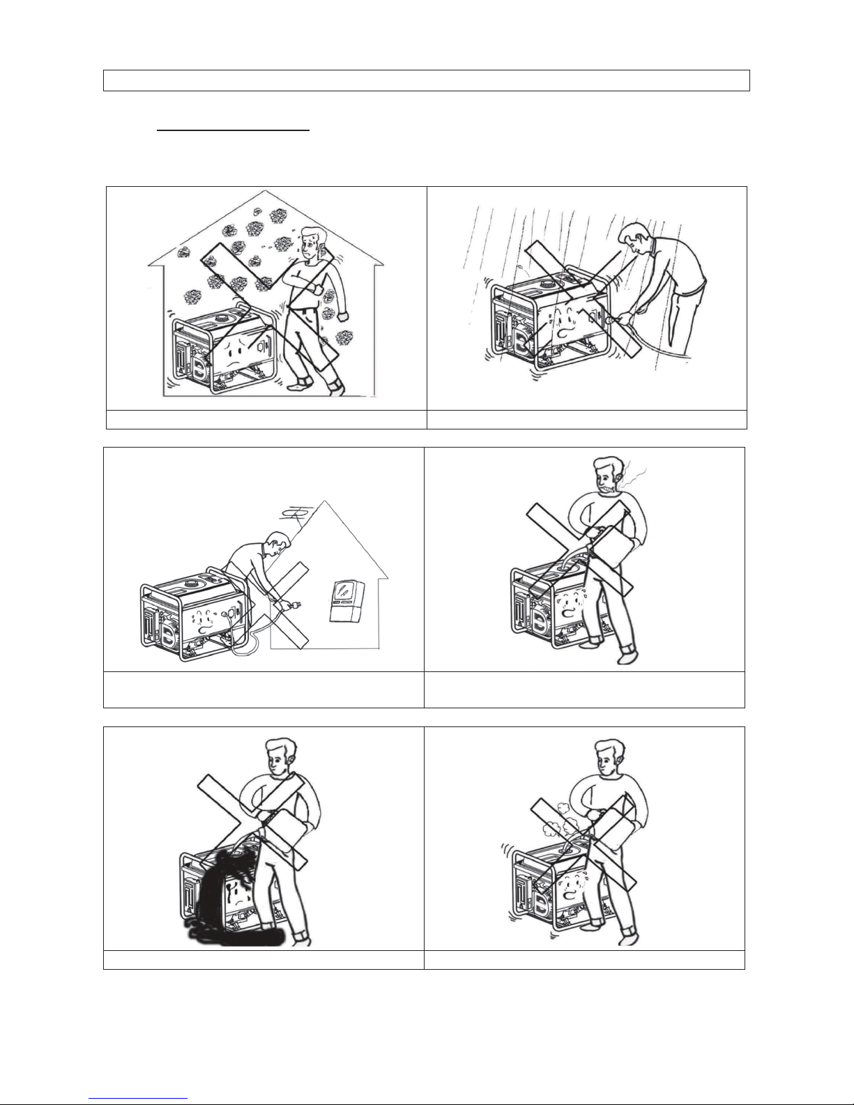
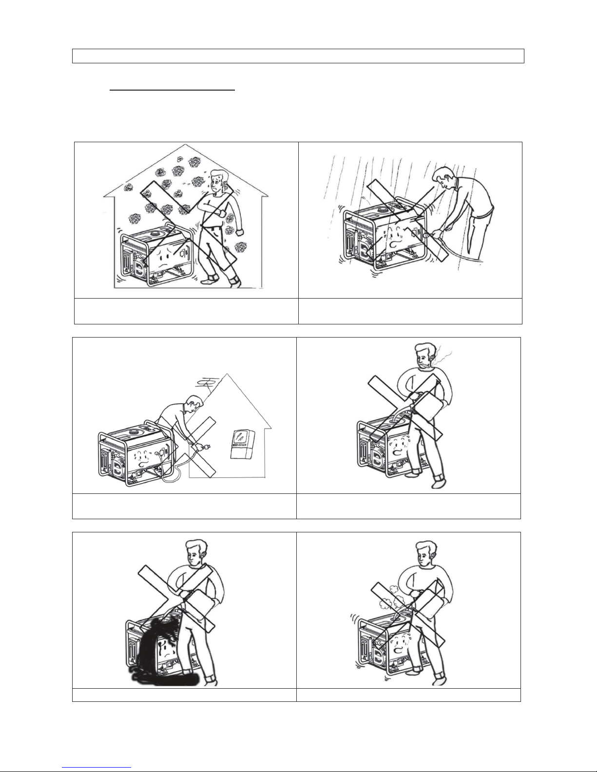
1. SAFETY STANDARD
Read and understand this owner’s manual before starting and operating your generator.
You can help prevent accidents by being familiar with your generator’s controls, and by
observing safe operating procedures.
Don’t operate indoors.
Don’t operate in the wet condition
Don’t directly connect to the household
power supply
Don’t smoke when refuelling
Don’t overflow the fuel when refuelling.
Stop the engine before refuelling
Page 5
5
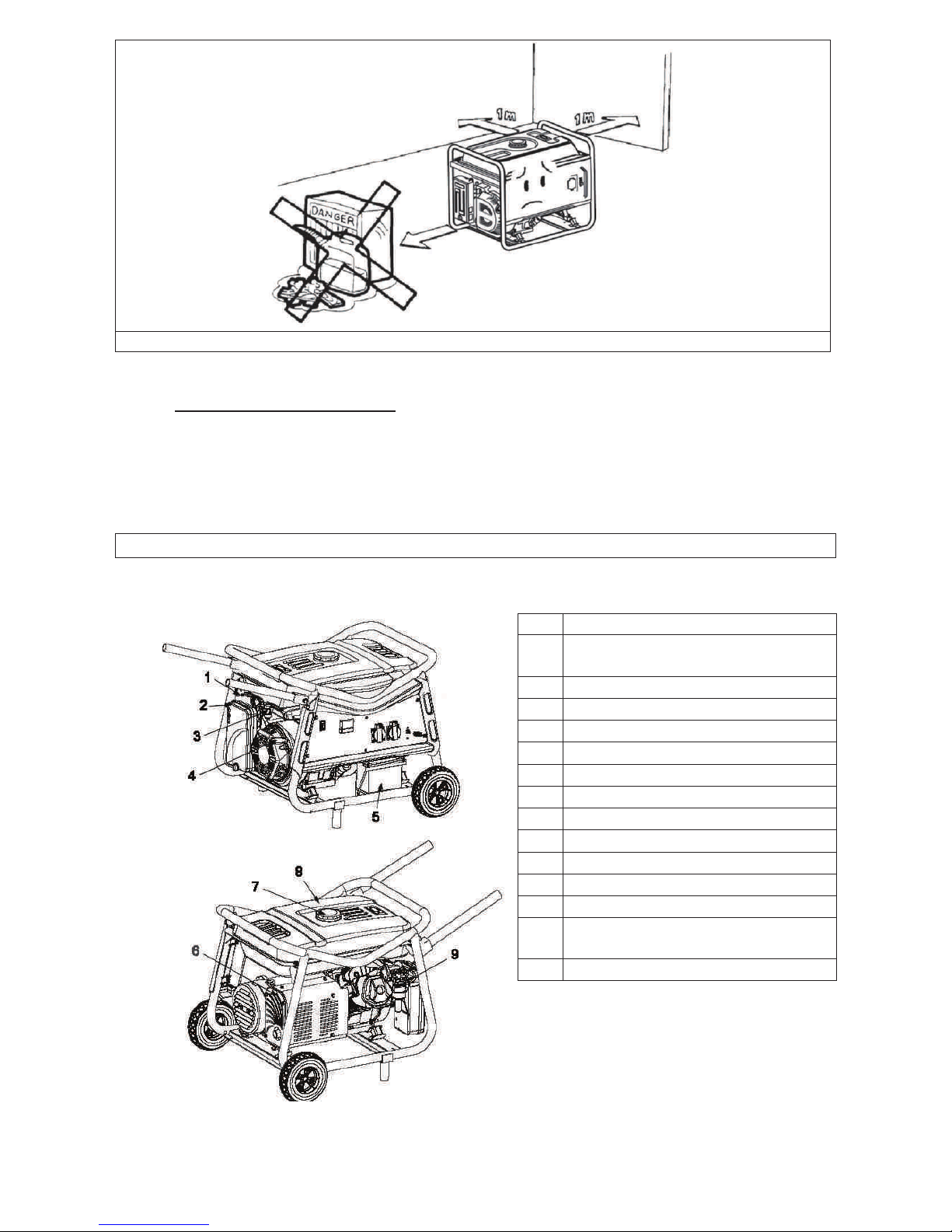
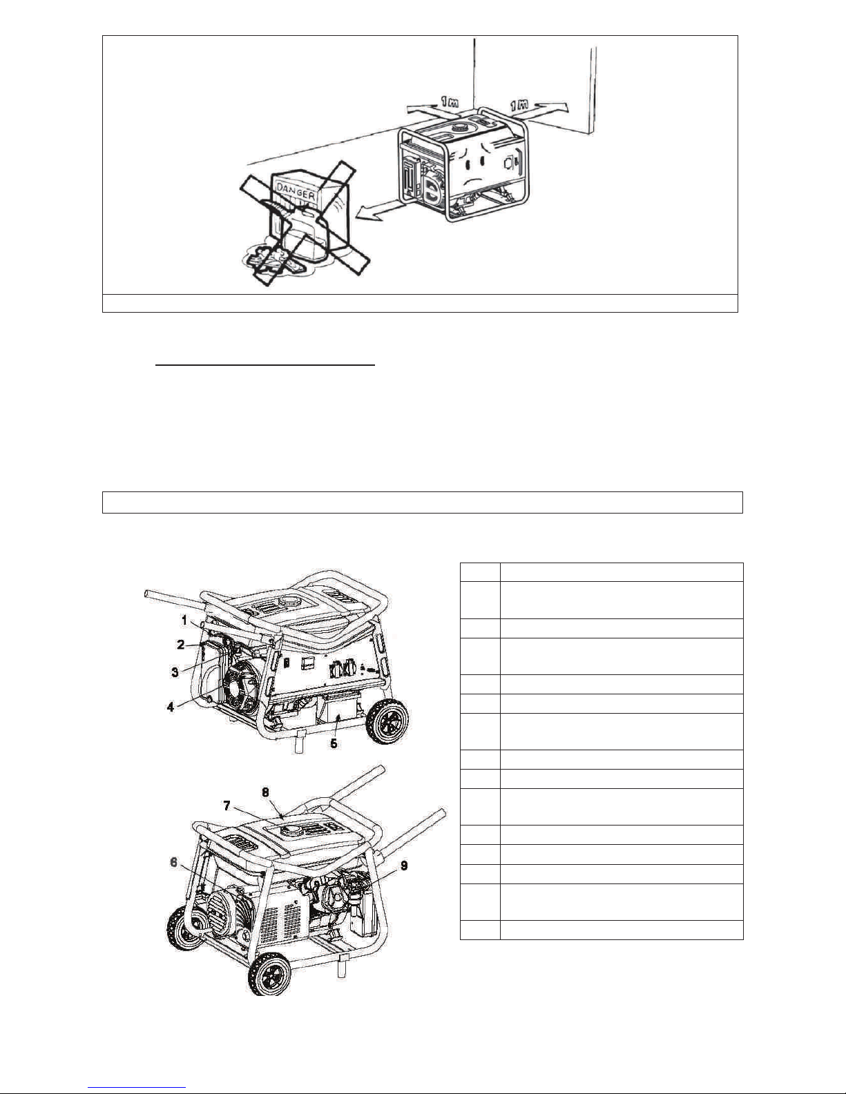
Please keep it 1m minimum away from the inflammable materials
2. SPECIAL REQUIREMENTS
· Electrical equipment including lines and plug connections should be free from
exposure.
· The circuit breakers should be matched with the generator equipment. If the circuit
breakers require replacement, they must be replaced with a circuit breaker having
identical ratings and performance characteristics
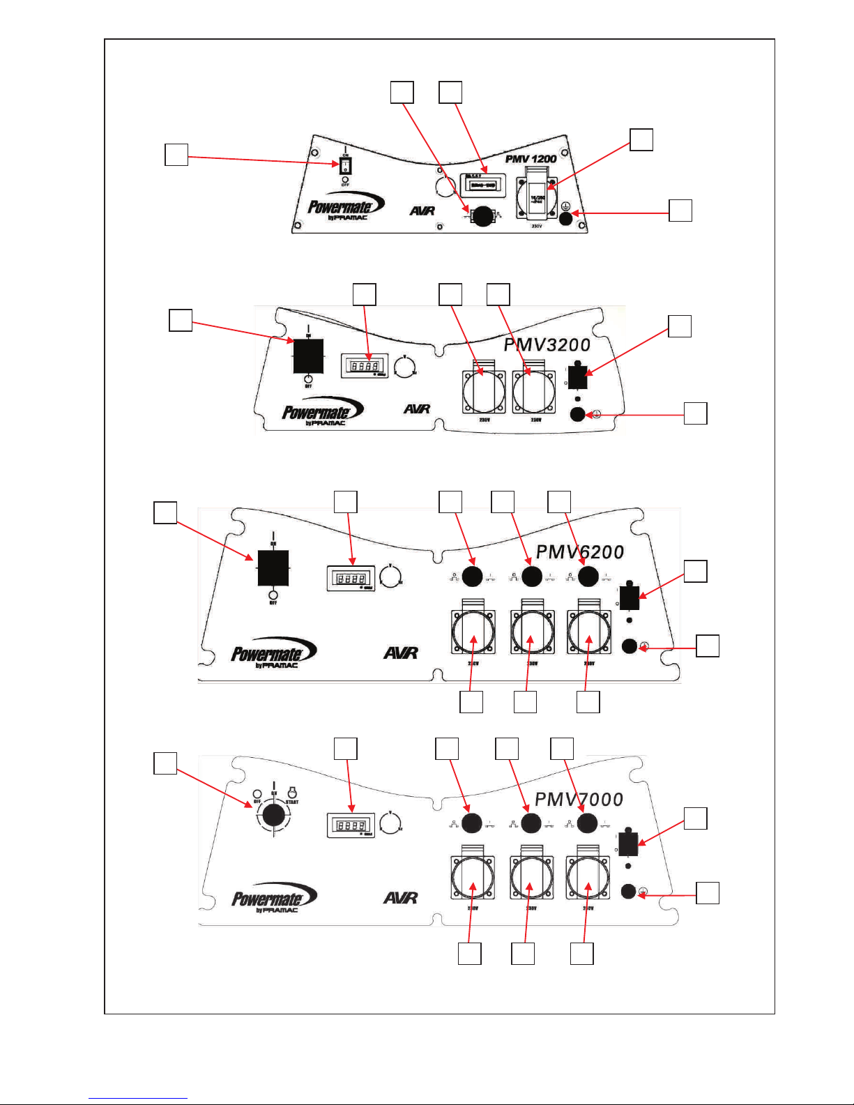
COMPONENT IDENTIFICATION
1
CHOKE LEVER
2
AIR CLEANER
3
FUEL VALVE
4
RECOIL-STARTER GRIP
5
BATTERY (PMV7000)
6
MUFFLER
7
FUEL TANK CAP
8
FUEL TANK
9
CARBURETOR
10
GENERATOR SWITCH
11
CIRCUIT BREAKER
12
SOCKET CIRCUIT BREAKER
13
SCHUKO SOCKETS
14
HOUR METER – VOLT METER
– FREQUENCY METER
15
GROUND TERMINAL
Page 6
6
10
11
14
13
15
14
13
13
11
15
10
10
14
12
12
12
11
15
13
13
13
14
12
12
12
11
15
10
13
13
13
Page 7
7
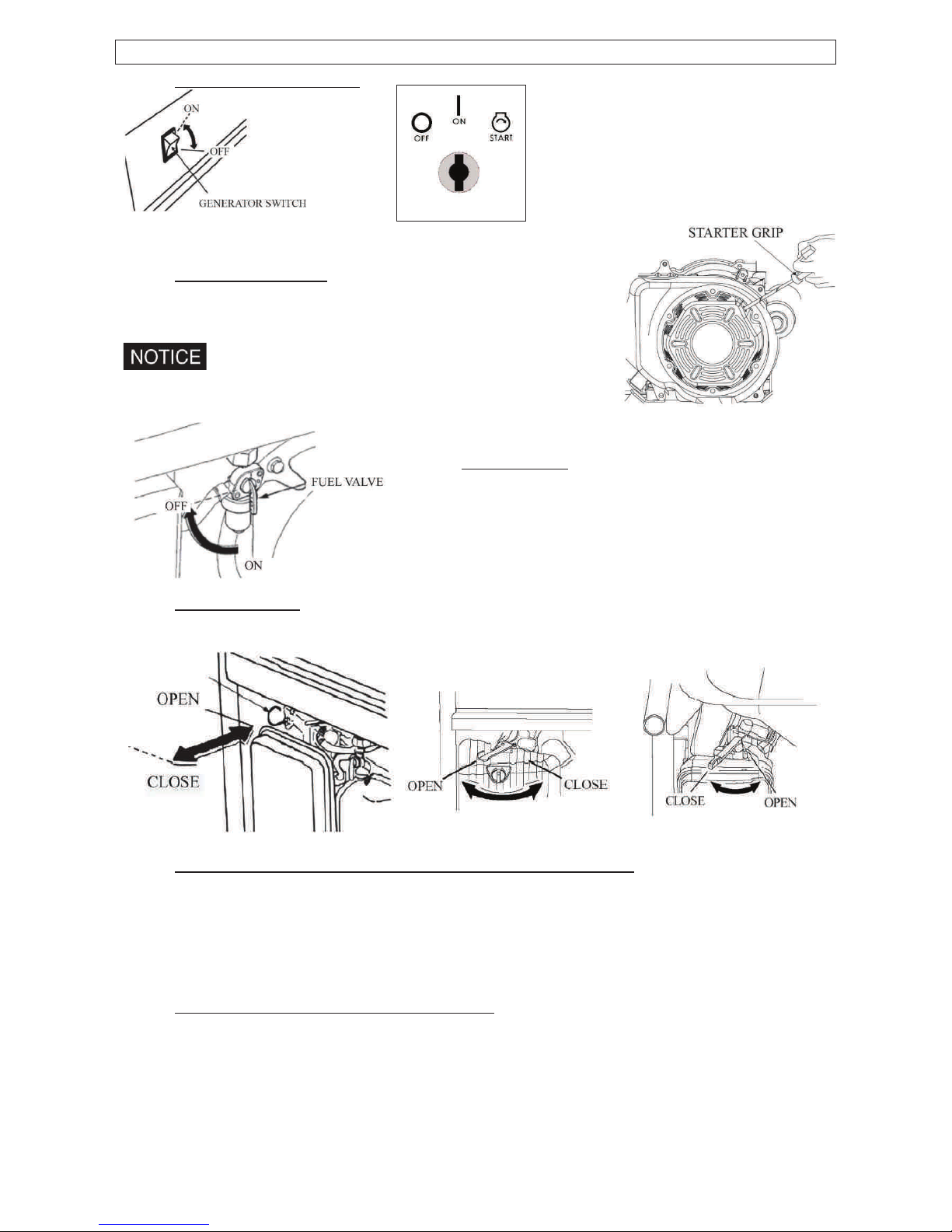
CONTROL
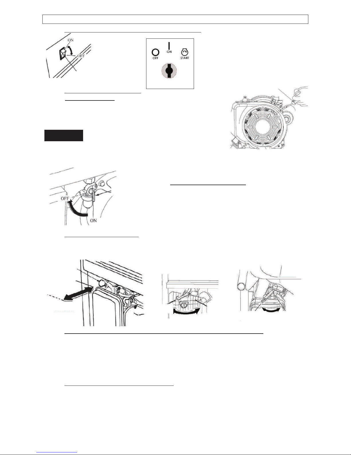
1. GENERATOR SWITCH
2. RECOIL STARTER
To start the engine, pull the starter grip lightly until resistance
is felt, then pull briskly.
Do not allow the starter to snap back against the engine.
Return it gently to prevent damage to the starter.
3. FUEL VALVE
The fuel valve controls fuel flowing from the fuel tank
to carburetor. Be sure to return the lever to “OFF”
after stopping the engine.
4. CHOKE LEVER
The choke lever is used to provide an enriched fuel mixture when starting a cold engine.
Slowly put the choke lever to “OPEN” position after the engine is heated.
5. AC CIRCUIT BREAKER / OVERCURRENT PROTECTIOR
The overload current will automatically switch off circuit breaker to avoid short circuit of the
load or overload. If the indicator of AC Overcurrent Protector is raised, the Over-current
Protector is now in the “OFF” position. Press the button of AC Over-current Protector to
the “ON” position again a few minute later. If the circuit breaker is switched OFF
automatically, switch the circuit breaker ON again.
6. OIL ALERT SYSTEM (Except PMV1200)
The oil alert system is specially designed to prevent engine damage caused by an
insufficient amount of oil in the crankcase. When the oil level in the crankcase falls down
below a safe limit, the oil alert system will automatically shut down the engine (though the
generator switch still remain in the ON position), so that the engine can’t be damaged
resulting from the insufficient amount of the oil.
Page 8
8
GENERATOR OPERATION
Generator operation environment:·
Temperature:-15Ԩ㹼40Ԩ·
Humidity: 95% lower.·
Height above sea level: 1000 m lower (If the area is 1000 m over, the power should be
lowered in operation).
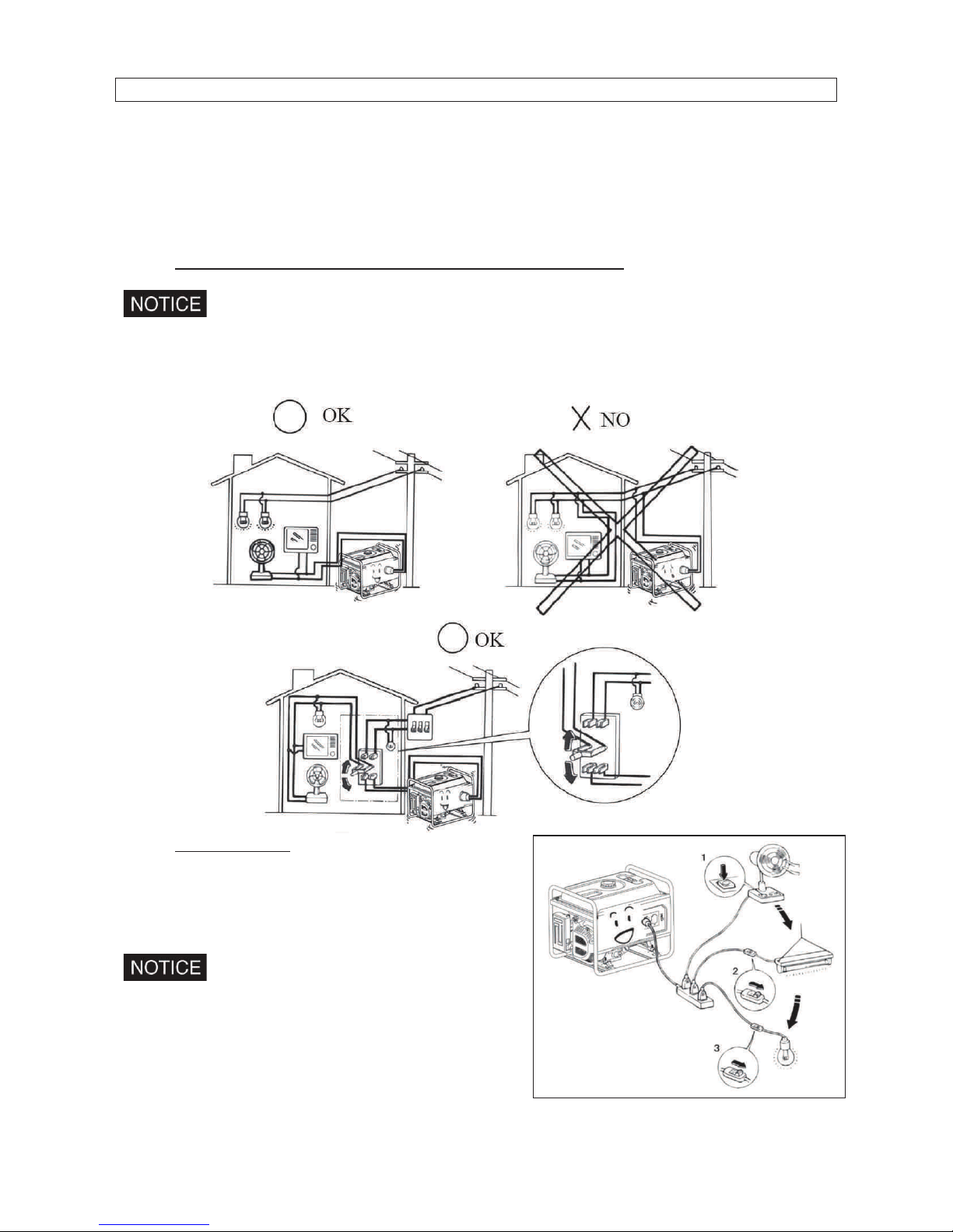
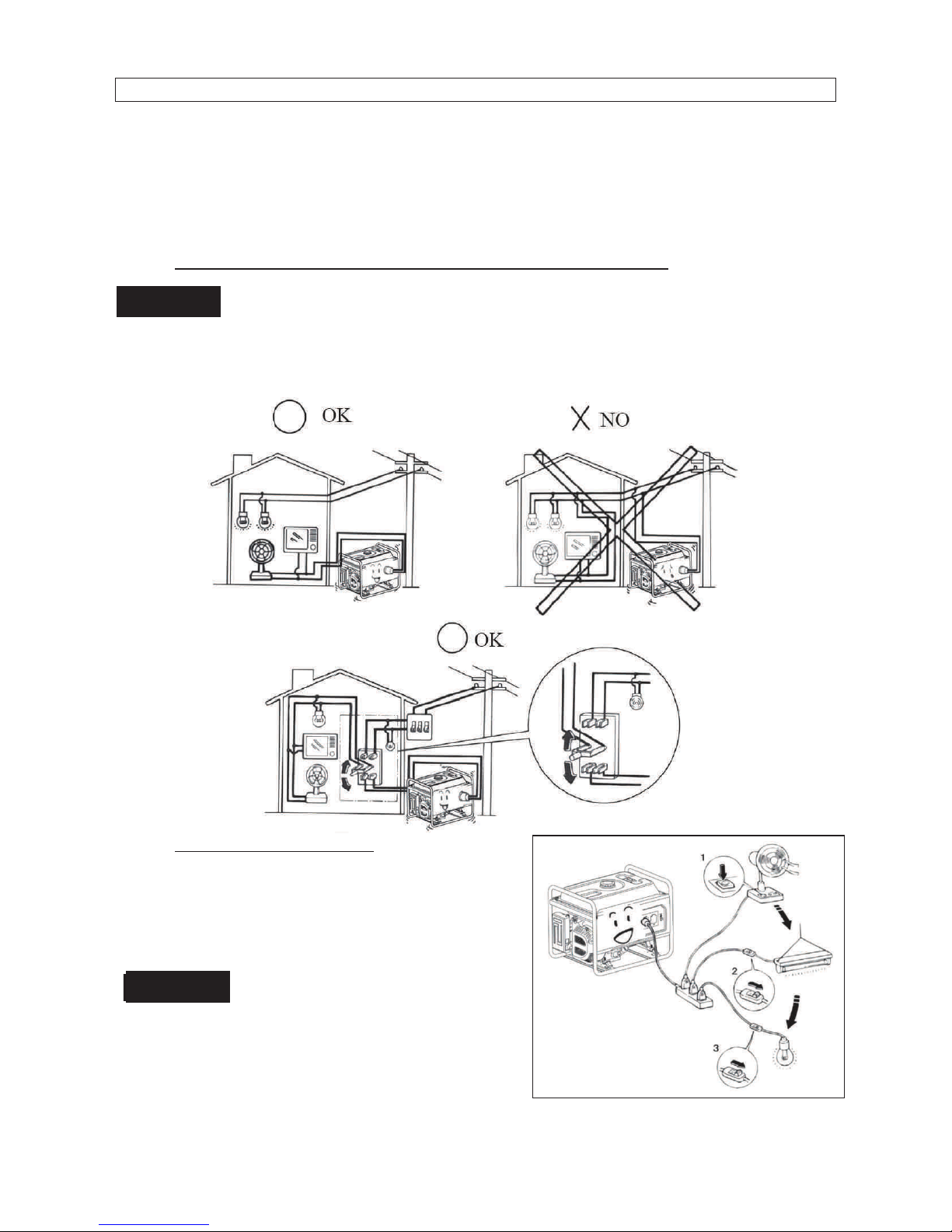
1. CONNECTION TO THE HOUSEHOLD POWER SUPPLY
When connecting the generator to the household power supply, connection must be
made by a qualified electrician. After connecting, carefully check electric
connections for their safety and reliability.
Unsafe connections will result in generator damage and risk of fire.
2. AC CURRENT
Before starting the generator, make sure that total
load appliance power (Total resistance, capacitive
and inductive) does not exceed rated power of the
generator
Overload operation will greatly shorten
generator service life.
If the generator set is connected to multi- loads or
electric appliances, please first connect to current
maximum, in turn, current second, and final,
current minimum.
Page 9
9
In general, capacitive and inductive load, especially, motor-driven devices have a big
starting current when starting.
3. HIGH ALTITUDE OPERATION
At high altitude, the standard carburetor air-fuel mixture will be excessively rich. Output
power will decrease, and fuel consumption will increase. Engine performance can be
improved by installing a smaller diameter main fuel jet in the carburetor and readjusting the
pilot screw. If you always operate the engine at altitudes above sea level 1000 meters,
have our company authorized dealer perform this carburetor modification. If not, lower load
power in operating generator.
Even equipped with suitable carburetor, engine horsepower will decrease approximately
3.5% for each 300 meter increase in altitude. The effect of altitude on horsepower will be
lowered greater than this if no carburetor modification is made.
If a carburetor for high altitude is equipped with engine suitable to a lower altitude,
the lean air fuel mixture will cause the engine output power lowering, over-heat and
seriously damage.
PRE-OPERATION CHEK
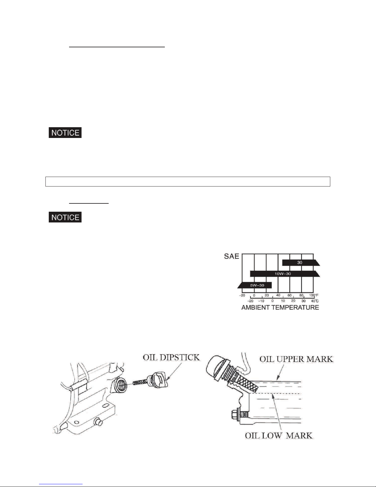
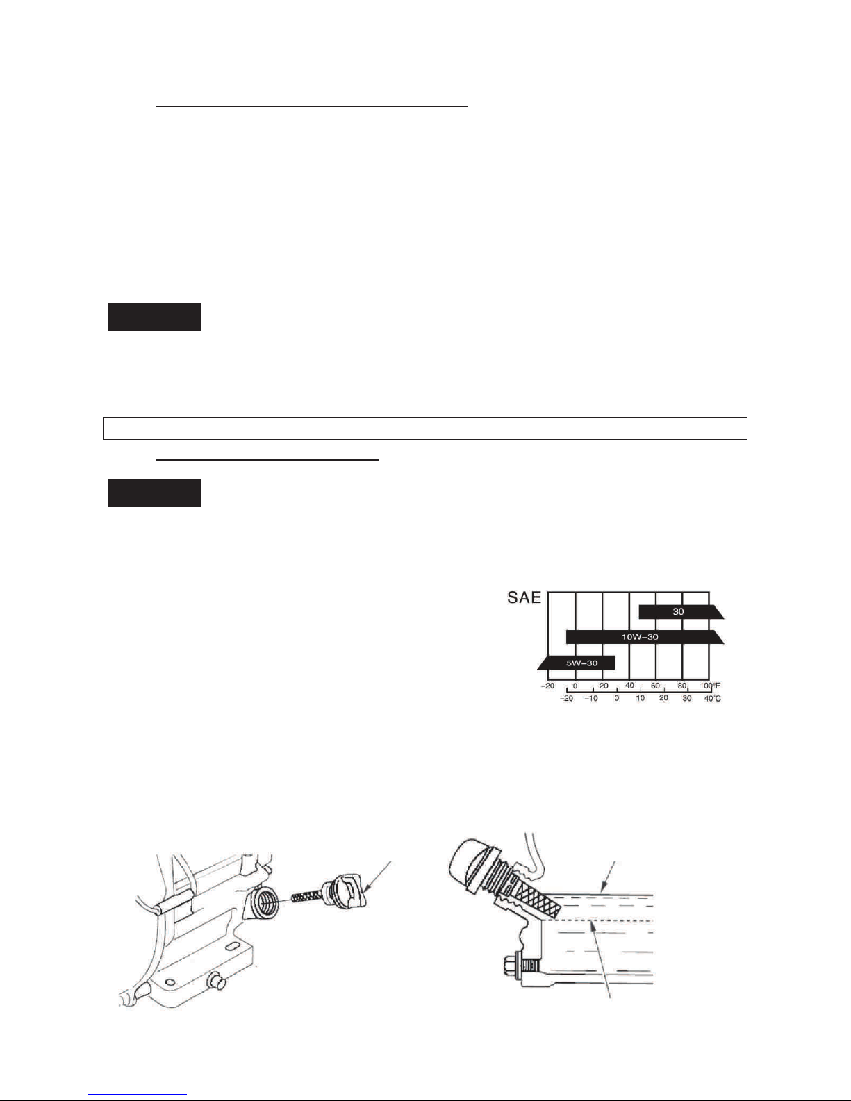
1. ENGINE OIL
Engine oil is a major factor affecting engine performance and service life. Nondetergent and 2-stroke engine oils will damage the engine and are not
recommended. Check the oil level before each use with the generator on a level
surface with the engine stopped.
Recommended oil
4-stroke gasoline oil
API service Classification's SF
or SAE10W-30 of equivalent SG class.
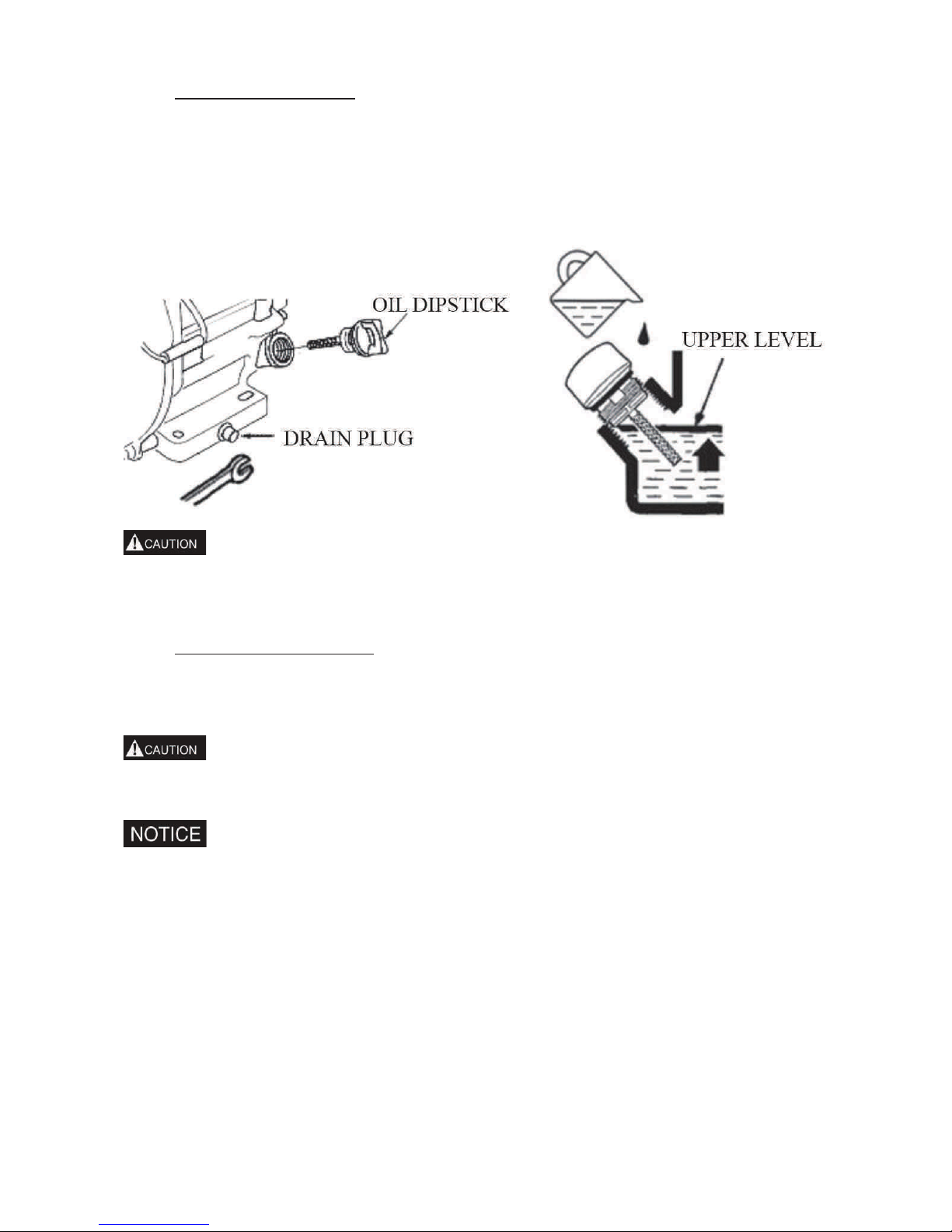
Method of check oil level:
Remove the oil filler cap and wipe the dipstick clean.
Check the oil level by inserting the dipstick into the filler neck without screwing it in.
If the level is low, add the recommended oil to the upper mark on the dipstick.
After adding, don’t forget to reinsert and screw down the oil dipstick.
Page 10
10
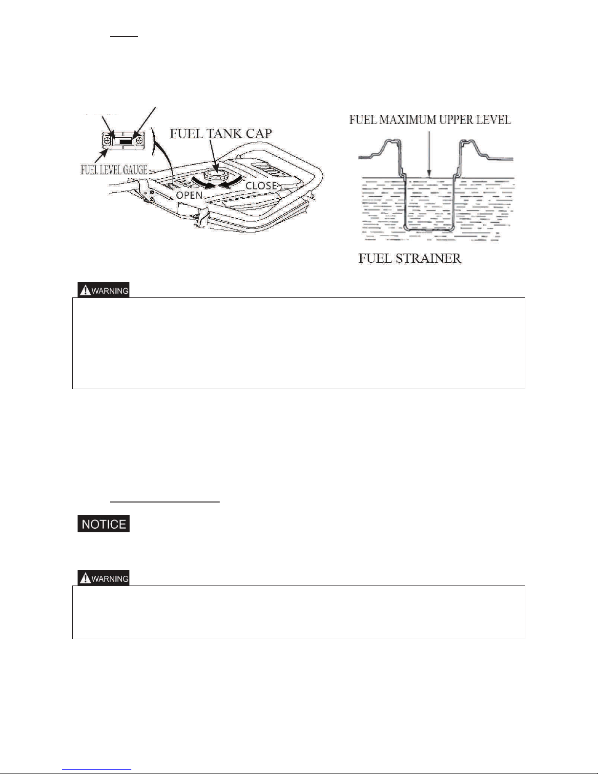
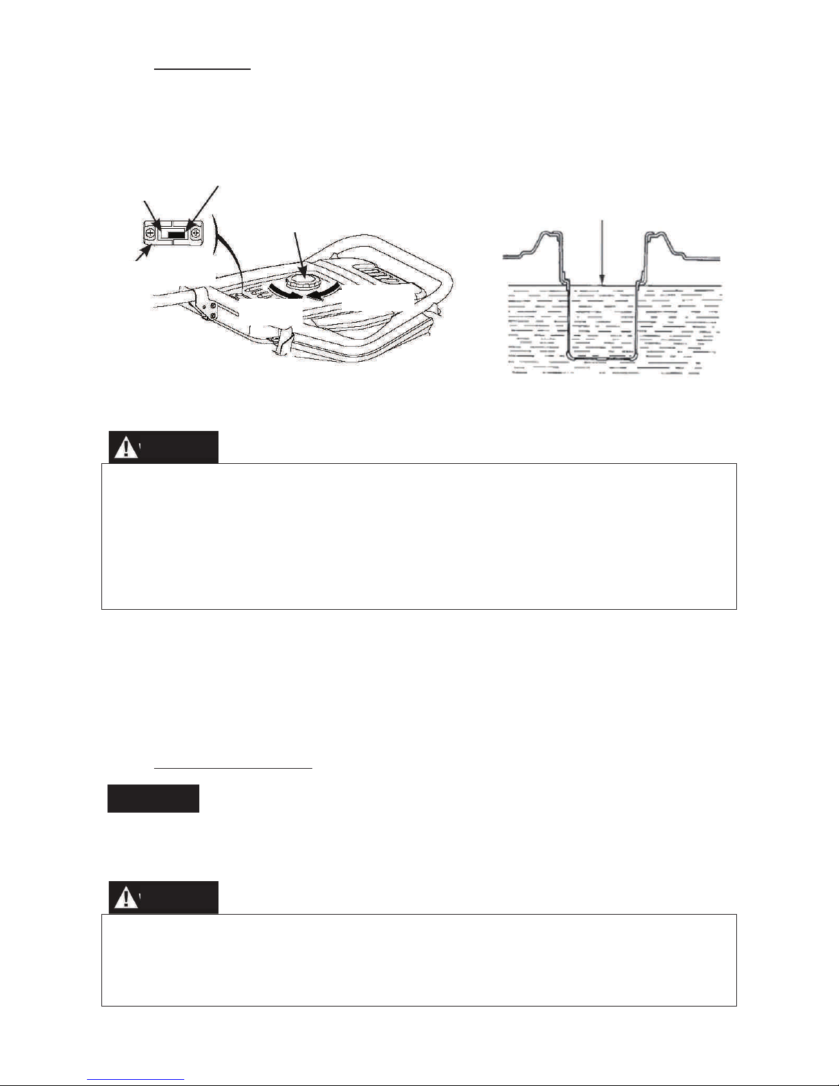
2. FUEL
1. Check the fuel level gauge,
2. Refill the tank if the fuel level is low. Do not fill above the shoulder of the fuel strainer.
3. Reinstall and screw down the fuel tank cap after refuelling.
• Refuel in a well-ventilated area with the engine stopped. Do not smoke or allow
flames or sparks in the area where the engine is refuelled or where gasoline is
stored.
• Do not overfill the fuel tank.
• Avoid repeated or prolonged contact with skin or breathing of vapour.
• Keep out of reach of children.
• Don’t use the oil and gasoline mixture or gasoline contained impurity.
Use gasoline with octane rating ≥90 .
We recommend unleaded gasoline because it produces fewer engine and spark plug
deposits and extends exhaust system life.
Never use stale or contaminated gasoline or oil/gasoline mixture. Avoid getting dirt or
water in the fuel tank.
3. BATTERY (PMV7000)
Don’t connect the battery positive and negative poles in reverse. Reversed
connection can seriously damage the generator set and battery.
• If operated improperly, the battery may be explosive and potentially hurt others
nearby. Keep the fire and inflammable materials far away from battery.
• The battery will release the explosive gas, please keep the fire far away from
battery. Keep the air ventilating when battery is charging and using.
EMPTY
FULL
Page 11

11
STARTING THE ENGINE
1. RECOIL STARTER
1. Remove all the loads out of the output.
2. Turn the fuel valve to the “ON” position.
3. Turn the AC circuit breaker to the “OFF” position.
4. Turn the choke lever to the “CLOSE” position.
Don’t close the choke when starting the engine in warm state
5. Turn the generator switch to the “ON” position.
6. Pull the starter grip until compression is felt, then pull briskly.
7. Turn the choke lever to the “OPEN” position after the engine is warm.
8. Don’t use electric apparatus before setting circuit breaker to the “ON” position.
2. ELECTRIC STARTING (PMV7000)
1. Remove all the loads out of the output.
2. Turn the fuel valve to the “ON” position.
3. Turn the choke lever to the “CLOSE” position.
Don’t close the choke when starting the engine in warm state.
4. Turning the generator switch to electric starting position.
5. After starting engine, immediately release generator switch and generator switch can
automatically return to open position.
6. Turn the choke lever to “OPEN” position after the engine is warm.
Turn the generator switch to electric starting position for more than 5 seconds can
damage the starting motor. If failing to start, release the switch and wait 10 seconds
before operating it again.
If the speed of the starting motor drops fast after a period of time, it means that the
battery should be recharged.
STOPPING THE ENGINE
1. Turn the AC circuit breaker to the OFF position.
2. Turn the generator switch to the OFF position.
3. Turn the fuel valve to the OFF position.
To stop the engine in an emergency, turn the generator switch to the OFF position.
Page 12

12
MAINTENANCE
Good maintenance is essential for safe, economical, and trouble-free operation. It will also
help reduce air pollution.
Exhaust gas contains poisonous carbon monoxide. Shut off the engine before
performing any maintenance. If the engine must be run, make sure the area is well
ventilated.
Periodic maintenance and adjustment is necessary to keep the generator in good
operating condition. Perform the service and inspection at the intervals shown in the
Maintenance schedule below:
1. Service more frequently when used in dusty areas.
2. These items should be serviced by an authorized generator dealer.
3. When used more often, only servicing according to above correct intervals can
insure the generator set long-term use.
Improper maintenance, or failure to correct a problem before operation, can cause a
malfunction in which you can be seriously hurt or killed.
Always follow the inspection and maintenance recommendations and schedules in
this owner’s manual.
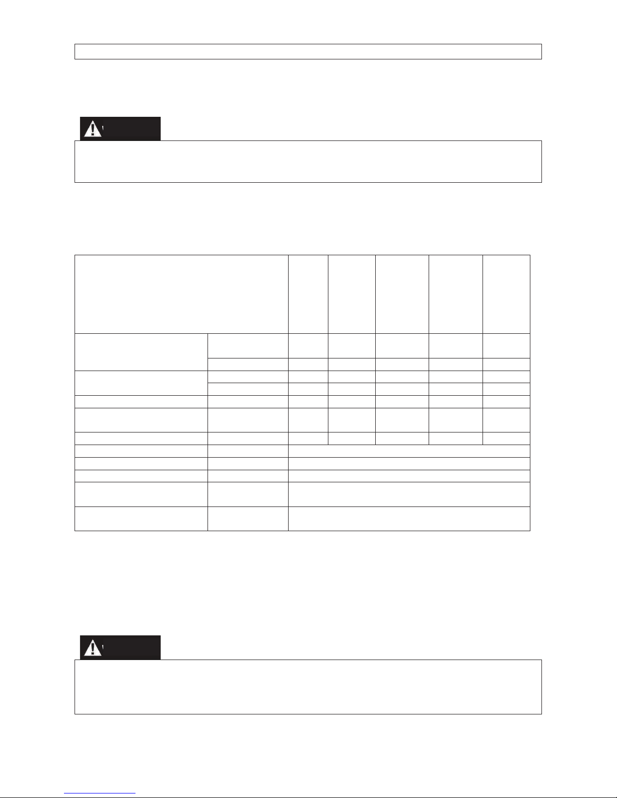
REGULAR SERVICE PERIOD
Each
Use
First
Month
or 20
Hrs.(3)
Every
3
Months
or 50
Hrs. (3)
Every
6
Months
or 100
Hrs. (3)
Every
Year
or 300
Hrs.
(3)
Engine oil
Check Level
○
Change
○ ○
Air cleaner
Check ○
Clean
○ (1)
Sediment Cup
Clean ○
Spark plug
Clean ○
renew
Valve clearance
Check-Adjust
○ (2)
Cylinder Cover
Clean
Every 300 Hours (2)
Fuel tank and strainer
Clean
Every 2 Years (2)
Fuel line
Replace
Every 2 Years (2)
PMV1200–PMV3200
Cylinder head and the
head of piston
Clean carbon
Every 125 hours (2)
PMV6200–PMV7000
Cylinder head and the
head of piston
Clean carbon
Every 250 hours (2)
Page 13
13
1. ENGINE OIL CHANGE
Drain the oil while the engine is warm to assure complete and rapid draining.
1. Remove the oil dipstick and drain plug to drain the oil.
2.Reinstall the drain plug, then tighten the plug securely.
3. Refill oil and check the oil level.
Oil capacity: PMV1200: 0.3L;
PMV 3200-PMV6200: 0.6L;
PMV7000 1.1L
Refer to the oil security card.
Dispose of the oil according to the local requirements
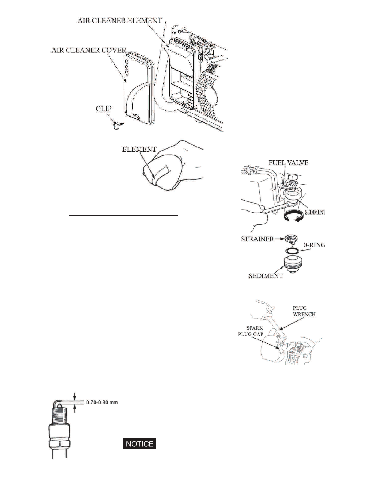
2. AIR CLEANER SERVICE
A dirty air cleaner will restrict air flow to the carburetor. To prevent carburetor malfunction,
service the air cleaner regularly. Service more frequently when operating the generator in
extremely dusty areas.
Using gasoline or flammable solvent to clean the filter element can cause a fire or
explosion. Use only soapy water or non flammable solvent.
Never run the generator without the air cleaner. If not, rapid engine wear will result.
1. Open the air cleaner clip and open the air cover. Check the air cleaner element for
any damage and clean.
2. If the air cleaner element is dirty, please clean the air cleaner element: Wash the
air cleaner element in a solution of household detergent and warm water, then rinse
thoroughly or wash in non flammable or high flash point solvent: Pour a few drops
of engine oil, on the oil filter element then squeeze out.
Page 14
14
3. Reinstall the air cleaner element and the cover.
3. FUEL SEDIMENT CUP CLEANING
1. Turn the fuel valve to the OFF position. Remove the
sediment cup, o-ring and strainer according to the
arrow direction.
2. Clean the sediment cup, and o-ring, and strainer in
non flammable or high flash point solvent.
3. Reinstall o-ring, and strainer and screw down the
sediment cup.
4. Turn the fuel valve ON and check for leaks.
4. SPARK PLUG SERVICE
1. Recommended spark plugs: F7RTC or other
equivalents
2. Remove the spark plug cap.
3. Use the plug wrench to remove the spark plug.
4. Visually inspect the spark plug if the insulator is
cracked. If cracked, replace with new the spark plug.
5. Measure the plug gap with a feeler gauge. Correct as
necessary by carefully bending the side electrode. The
gap should be: 0.70-0.80 mm.
6. Check the spark plug washer for damage.
7. Reinstall the spark plug, tighten it with plug wrench and impact the washer. Reinstall
the spark plug accurately.
Please use the spark plug with suitable heat range.
Page 15
15
STORAGE
Do not touch a hot engine or exhaust system to avoid burns or fires. Let the engine
cool before storing the generator.
If storing the unit for an extended period, be sure the storage area is free of excessive
humidity and dust.
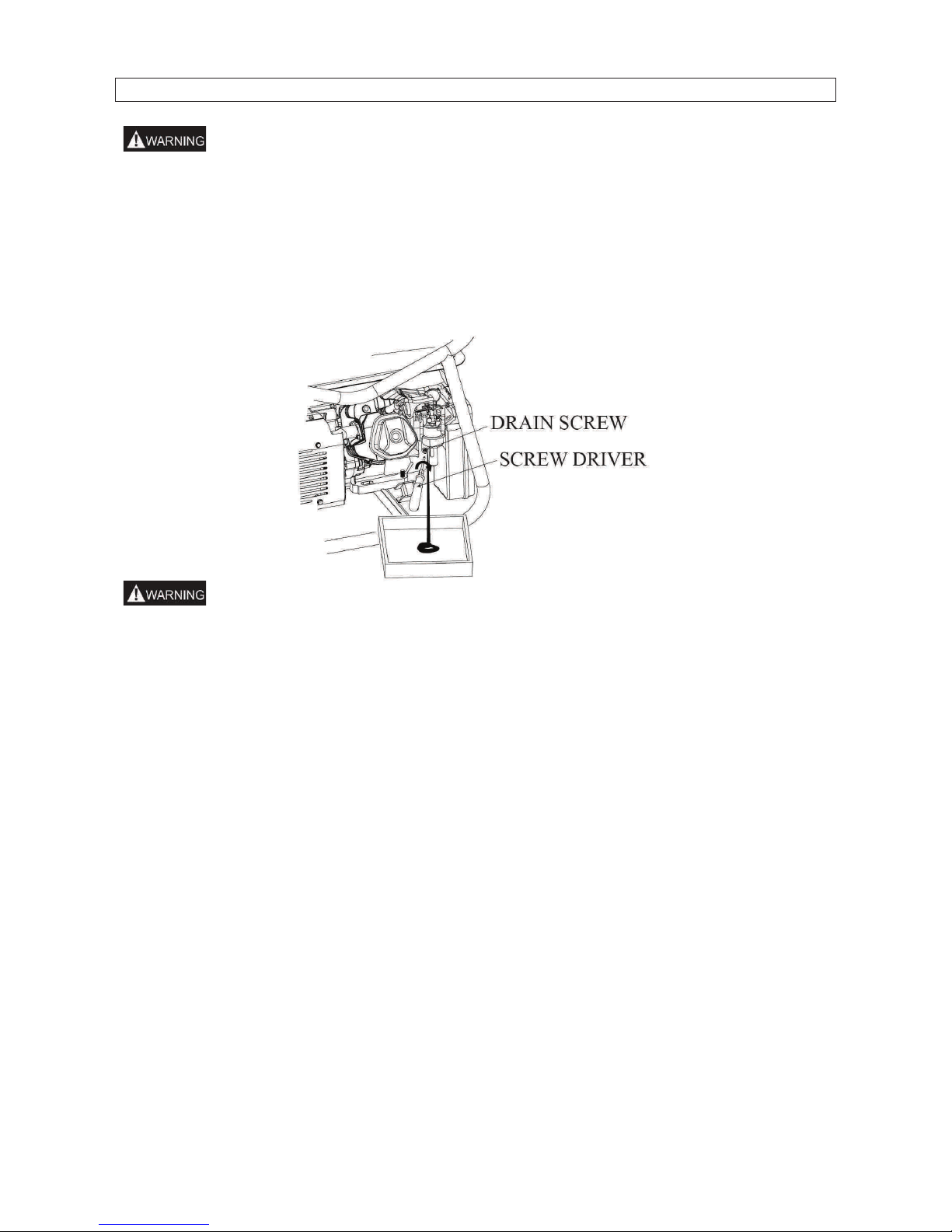
1. Drain the fuel in the fuel tank out, clean strainer, o-ring and sediment cup, then
reinstall. Drain fuel out of the carburettor by loosening the drain screw, then
reinstall and screw down the carburetor screw.
Gasoline is extremely flammable and is explosive under certain conditions. Drain
fuel in a well ventilated area with the engine stopped. Do not smoke or allow flames
or sparks in the area during this procedure.
2. Screw the oil dipstick off and screw the drain bolt off the crankcase to completely
drain the oil out. Then screw down the drain bolt and fill fresh oil to upper mark,
finally reinstall the oil dipstick.
3. Remove the spark plug, and pour about a tablespoon of clean engine oil into the
cylinder. Crank the engine several revolutions to distribute the oil, then reinstall the
spark plug.
4. Slowly pull the starter grip until resistance is felt. Leave the intake and exhaust
valves in the closed position.
5. Place the generator in the clean area.
Page 16
16
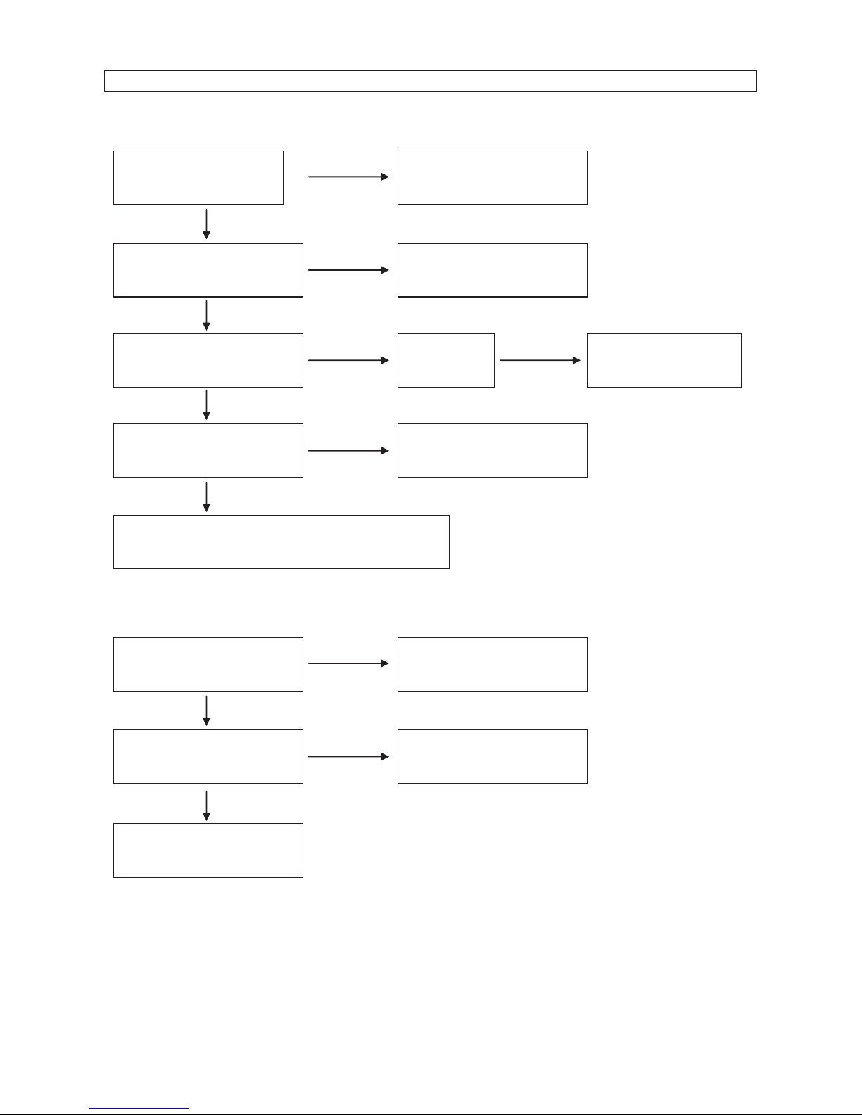
TROUBLESHOOTING
ENGINE UNABLE TO START:
NO POWER SUPPLY:
Is there fuel in the tank?
Refill the fuel tank.
Is there enough oil in the
engine?
Add the recommended oil.
Is there a spark from the
spark plug?
Replace the
spark plug
Take the generator to
an aut
h
orized dealer.
Is the fuel reaching the
carburetor
?
Check and clean the fuel
sediment cup.
If the engine still does not start, take the
generator to an aut
h
orized generator dealer.
NO
NO
NO
NO
Still NO
spark
YES
YES
YES
YES
Is the AC circuit breaker
ON?
Turn the AC circuit
breaker ON.
Check the electrical
appliance or equipment for
any defects.
Take the generator to an
aut
horized dealer.
NO
NO
YES
Replace the electrical
appliance or equipment.
YES
Page 17
17
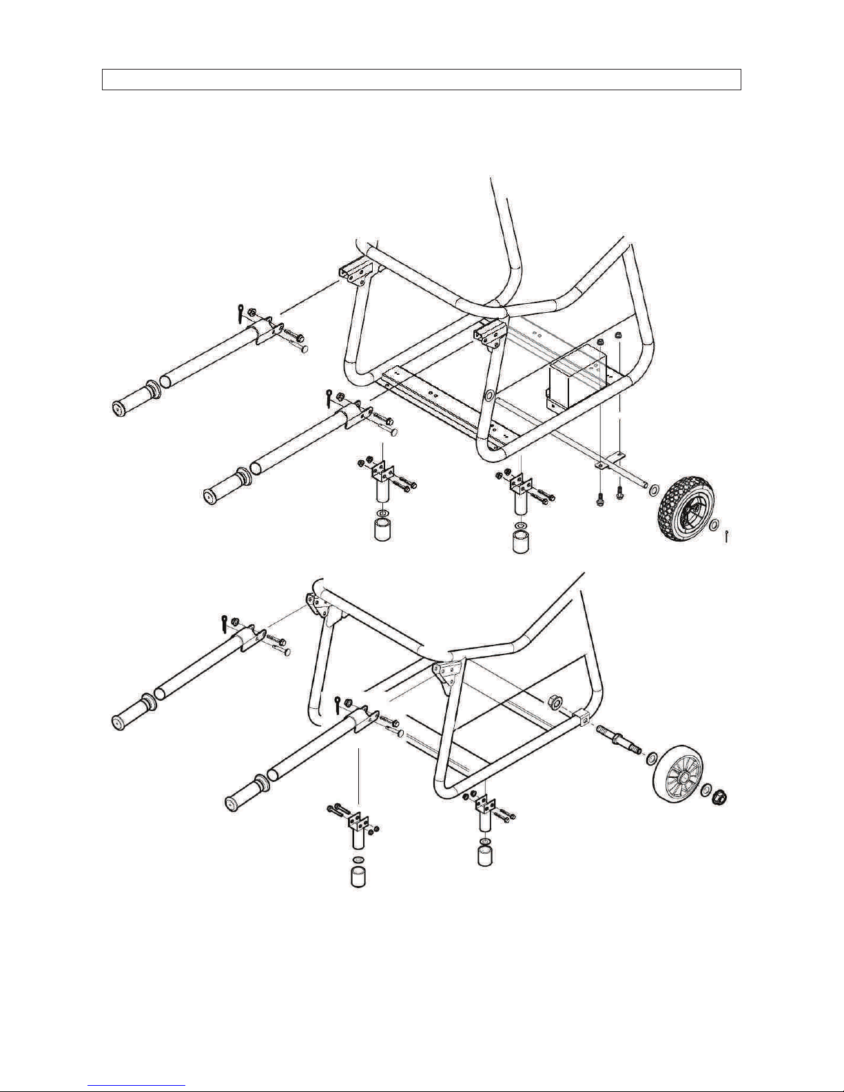
WHEEL KIT – PMV3200 – PMV6200 – PMV7000
1. Install the two wheels on the wheel axle with gaskets and pins.
2. Install the wheel on the bottom plate of the generator frame with bolts and nuts.
3. Fix the handle on the frame.
Page 18
18
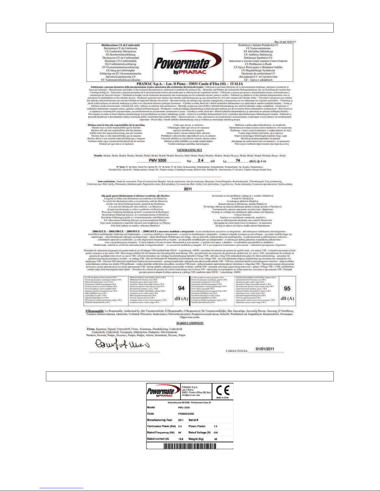
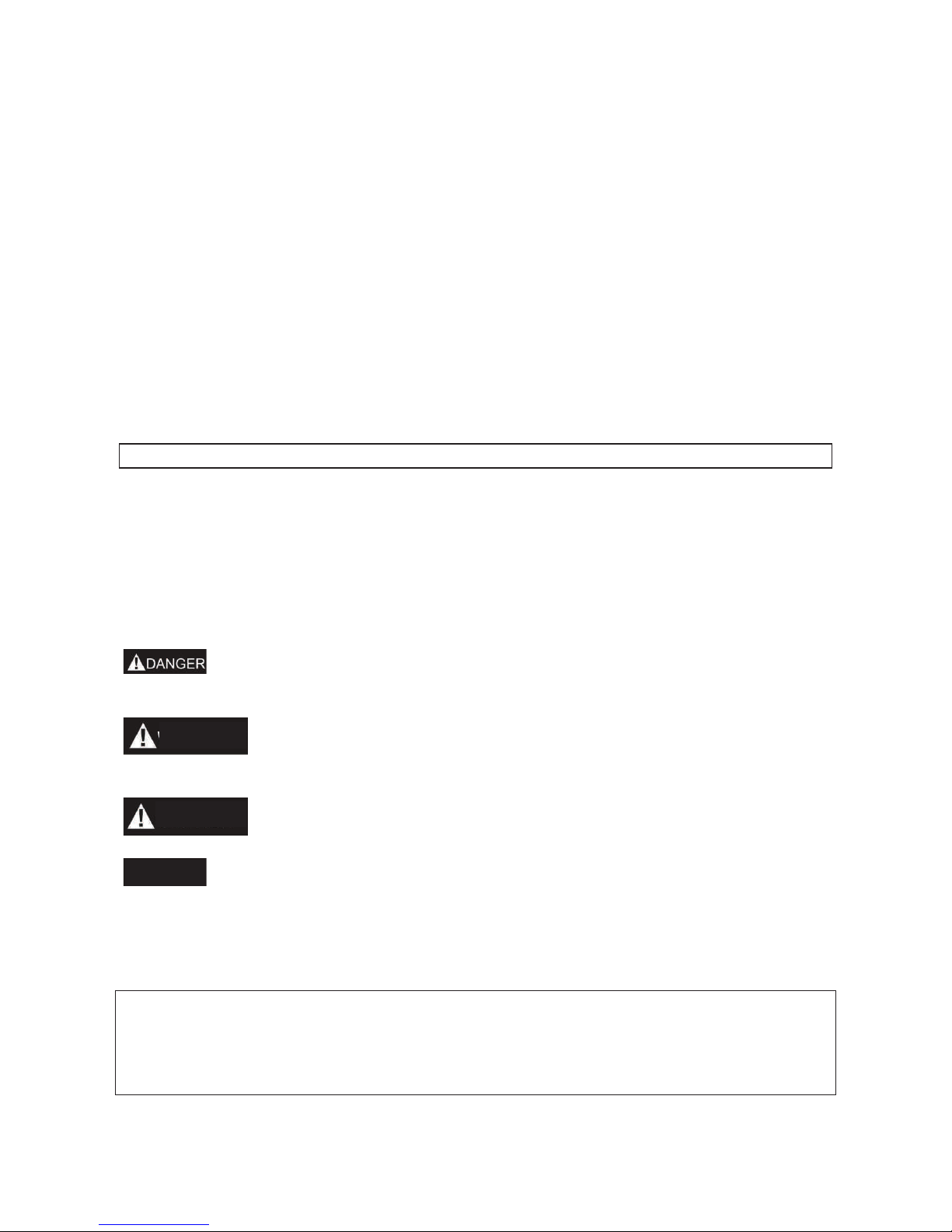
CE DELARATION
SERIAL NUMBER PLATES
Page 19

Manuel de l’utilisateur
PMV 1200
PMV 3200
PMV 6200
PMV 7000 (Batterie)
Page 20
20
Nous vous remercions pour avoir choisi un groupe électrogène de notre société.
Ce manuel contient toutes les informations nécessaires à l’utilisation de celui-ci. Veuillez le
lire attentivement avant toute utilisation. Une utilisation conforme et qui respecte les
normes de sécurité vous aidera à obtenir les meilleurs résultats.
Toutes les informations contenues dans ce manuel correspondent aux dernières
informations sur le produit disponibles au moment où ce manuel passe sous presse. Elles
peuvent par conséquent être quelques peu différentes par rapport aux composants
effectifs de nos groupes à la suite de révisions ou d’autres modifications.
Notre société se réserve le droit d’apporter toute modification, à tout moment, sans aucun
avis préalable et sans qu’aucune obligation ne lui soit faite en ce sens. Toute reproduction,
même partielle, de ce document est interdite sans le consentement écrit de notre société.
Le présent manuel doit être considéré comme une partie intégrante du groupe électrogène
et devra toujours accompagner ce dernier, même en cas de revente.
MESSAGES DE SÉCURITÉ
Votre sécurité ainsi que celle des autres sont très importantes. Nous fournissons
d’importants messages de sécurité dans ce manuel ainsi que sur le groupe électrogène.
Veuillez lire ces messages très attentivement.
Un message de sécurité avertit des risques potentiels de blessures de l’utilisateur ou de
toute autre personne. Tout message de sécurité est précédé d'un symbole de sécurité
d'alerte et d'un de ces trois mots: DANGER, AVERTISSEMENT, ou ATTENTION. Ces
termes signifient:
BLESSURES MORTELLES ou GRAVES BLESSURES si vous ne
respectez pas les instructions.
Risques de BLESSURES MORTELLES ou de GRAVES BLESSURES
si vous ne respectez pas les instructions.
Risques de BLESSURES si vous ne respectez pas les instructions.
Risque d’abîmer votre groupe électrogène ou tout autre équipement si
vous ne respectez pas les instructions.
ADDRESSE DU FABRICANT:
PRAMAC S.p.A.
Loc. Il Piano
CAP 53031, Casole D’Elsa (SI)
ITALIE
AVERTISS.
ATTENTION
NOTA
Page 21

21
SOMMAIRE
AVIS DE SÉCURITÉ ...............................................................................................................................................22
REPÉRAGE DES COMPOSANTS ........................................................................................................................23
ORGANES DE COMMANDE .................................................................................................................................25
FONCTIONNEMENT DU GROUPE ÉLECTROGÈNE ........................................................................................26
VÉRIFICATIONS AVANT LA MISE EN SERVICE ..............................................................................................27
MISE EN MARCHE DU MOTEUR .........................................................................................................................29
ARRÊT DU MOTEUR .............................................................................................................................................29
ENTRETIEN .............................................................................................................................................................30
REMISAGE ..............................................................................................................................................................33
RECHERCHE DE PANNES ...................................................................................................................................34
KIT DES ROUES – PMV3200 – PMV6200 – PMV7000 ......................................................................................35
DÉCLARATION CE ................................................................................................................................................36
PLAQUETTES NUMÉROS DE SÉRIE .................................................................................................................36
Page 22
22
AVIS DE SÉCURITÉ
1. NORMES DE SÉCURITÉ
Avant de mettre en marche votre groupe électrogène, il est nécessaire de lire et
comprendre parfaitement toutes les informations et les manoeuvres. Vous préviendrez les
accidents en connaissant bien les organes de commande de votre groupe et en
respectant les procédures opérationnelles.
Ne jamais utiliser le groupe à l’intérieur.
Ne jamais utiliser le groupe en milieu
humide
Ne jamais connecter le groupe directement
à une prise domestique
Ne jamais fumer en faisant le plein
Ne jamais déborder en faisant le plein.
Arrêter le moteur avant de refaire le plein
Page 23
23
Garder le groupe à au moins 1m de tout matériel inflammable
2. EXIGENCES PARTICULIÈRES
· Le matériel électrique, dont les prises et les fils, doit être intact et ne pas présenter
de câbles dénudés.
· Les disjoncteurs thermiques et magnétothermiques doivent être spécialement
prévus pour le groupe électrogène. Si ces derniers doivent être remplacés, ils
doivent l’être par des disjoncteurs ayant des valeurs nominales et des
caractéristiques identiques.
REPÉRAGE DES COMPOSANTS
1
MANETTE DU STARTER
2
FILTRE À AIR
3
VANNE DU CARBURANT
4
POIGNÉE DU LANCEUR
RÉENROULEUR
5
BATTERIE (PMV7000)
6
SILENCIEUX
7
BOUCHON RÉSERVOIR
CARBURANT
8
RÉSERVOIR CARBURANT
9
CARBURATEUR
10
CONNECTEUR GROUPE
ÉLECTROGÈNE
11
DISJONCTEUR
12
DISJONCTEUR PRISE
13
PRISES SCHUKO
14
HOROMÈTRE – VOLTMÈTRE –
FRÉQUENCEMETRE
15
PRISE DE TERRE
Page 24

24
10
11
14
13
15
14
13
13
11
15
10
10
14
12
12
12
11
15
13
13
13
14
12
12
12
11
15
10
13
13
13
Page 25
25
ORGANES DE COMMANDE
1. CONTACTEUR DU GROUPE ÉLECTROGÈNE
2. POIGNÉE DU LANCEUR
RÉENROULEUR
Pour le démarrage, saisir la poignée du lanceur puis tirer
lentement jusqu’à rencontrer une légère résistance. Tirer
ensuite par un mouvement court et sec.
Ne pas lâcher brusquement la poignée du lanceur pour
éviter qu’il ne cogne brusquement contre le moteur.
Accompagner l’enroulement pour éviter d’endommager le lanceur.
3. VANNE DU CARBURANT
La vanne de carburant contrôle le passage du
carburant du réservoir vers le carburateur. Faire
attention à bien mettre sur “OFF” la manette après
avoir arrêté le moteur.
4. MANETTE DU STARTER
La manette du starter a été prévue pour fournir un mélange de carburant enrichi lorsqu’on
démarre avec le moteur à froid. Tirer lentement la manette du starter en position “OPEN”
après réchauffement du moteur.
5. DISJONCTEUR C.A. / PROTECTION CONTRE LES SURCHARGES
Tout courant de surcharge déclenche immédiatement le disjoncteur pour éviter tout courtcircuit et toute surcharge. Si l’indicateur de surcharge C.A. intervient, le protecteur de
surcharge passe à la position “OFF”. Remettre le bouton du protecteur de surcharge C.A.
sur la position “ON” quelques minutes après. Si le disjoncteur s’éteint (OFF)
automatiquement, le rallumer (ON).
6. SÉCURITE D'HUILE (Sauf PMV1200)
Cette sécurité a été spécialement conçue pour prévenir tout dégât au moteur à cause d’un
manque d’huile dans le bloc moteur. Lorsque le niveau d’huile dans ce dernier descend en
dessous d’un certain seuil, la sécurité d'huile arrête le moteur (même si l’interrupteur du
groupe électrogène reste allumé (ON)) et ce, afin d’éviter tout dégât au moteur à cause
d’un niveau d'huile insuffisant.
NOTA
CONTACTEUR GROUPE
ÉLECTROGÈNE
POIGNÉE DU LANCEUR
VANNE DU
CARBURANT
OUVERT
OUVERT
OUVERT
FERME
FERME
FERME
Page 26
26
FONCTIONNEMENT DU GROUPE ÉLECTROGÈNE
Environnement pour le fonctionnement du groupe:
Température:-15Ԩ㹼40Ԩ·
Degré hygrométrique: moins de 95%·
Altitude s/m: moins de 1000 m (si le lieu d’utilisation se trouve à plus de 1000 m, la
puissance sera diminuée au cours du fonctionnement).
1. CONNEXION AU RÉSEAU DE DISTRIBUTION DOMESTIQUE
La connexion du groupe électrogène au réseau de distribution domestique sera
uniquement effectuée par un électricien qualifié. La connexion effectuée, en vérifier
le bon état et les conditions de sécurité en l'absence desquelles le groupe
générateur pourrait subir des dégâts, brûler ou être la source d'un incendie.
2. COURANT ALTERNATIF
Avant de mettre le groupe électrogène en marche,
vérifier que la charge totale de l’appareil
(Résistance totale, capacitive et inductive) n’est
pas supérieure à la charge nominale du groupe
électrogène.
Tout fonctionnement en conditions de
surcharge risque de réduire considérablement
la durée de vie de votre groupe électrogène.
Si vous devez alimenter plusieurs charges
simultanément, vous devez d’abord connecter la charge plus importante lourde puis les
autres jusqu’à la plus faible.
NOTA
NOTA
Page 27
27
En général, les engins motorisés avec charge capacitive et inductive, surtout, présentent
une charge élevée au démarrage.
3. FONCTIONNEMENT EN HAUTE ALTITUDE
En haute altitude, le mélange carburé du carburateur est trop riche. La puissance
dégagée diminue et la consommation de carburant grimpe. On peut améliorer les
performances du moteur en installant un gicleur principal de plus petit diamètre sur le
carburateur et en réglant la vis pilote. Si le moteur fonctionne toujours à des altitudes de
1000 mètres au-dessus du niveau de la mer, demandez à un revendeur autorisé de notre
société d'effectuer cette modification sur le carburateur. Sinon, vous obtiendrez moins de
charge pendant le fonctionnement du groupe électrogène.Car même si vous avez un
carburateur adéquat, la puissance de votre moteur baissera d’environ 3.5% à chaque
élévation de hauteur de 300 m. L'impact de l'altitude sur la puissance dégagée se fera
sentir davantage si aucune modification n'est apportée au carburateur.
Si le carburateur qui est utilisé à hauteur élevée est équipé d’un moteur convenant
aux basses altitudes, le maigre mélange carburé sera à l'origine d'une diminution de
la puissance dégagée par le moteur, ce qui provoquera une surchauffe et des
dégâts sérieux.
VÉRIFICATIONS AVANT LA MISE EN SERVICE
1. NIVEAU D'HUILE DU MOTEUR
L’huile moteur est un élément essentiel pour les bonnes performances et la
longévité de votre groupe électrogène. Les huiles moteur non détergentes et 2
temps endommageront le moteur et sont dès lors à déconseiller. Avant chaque
démarrage vérifier le niveau d'huile moteur. La
vérification se fera le groupe posé sur une
surface horizontale avec moteur arrêté.
Huile conseillée
Huile pour moteur essence 4 temps
API Service classe SF
ou SAE10W-30 ou classe SG équivalente.
Méthode pour vérifier le niveau d’huile:
Retirer le bouchon de remplissage et essuyer la jauge de niveau. Contrôler le niveau
d’huile en introduisant la jauge dans le col de remplissage sans la visser.
Si le niveau d’huile est bas, faire l’appoint jusqu’au cran supérieur de la jauge.
Après avoir fait l’appoint, n’oubliez pas de remettre la jauge en place et de la revisser.
NOTA
NOTA
TEMPÉRATURE AMBIANTE
AUGE D’HUILE
CRAN HUILE SUPÉRIEUR
CRAN HUILE INFÉRIEUR
Page 28
28
2. CARBURANT
1. Contrôler l’indicateur de niveau de carburant.
2. Faire le plein si le niveau de carburant est bas. Ne pas dépasser le niveau de l’épaule
du décanteur.
3. Après avoir fait le plein, remettre le bouchon de remplissage et le visser.
• Faire le plein dans un endroit bien aéré et avec moteur à l’arrêt. Ne pas fumer ou
approcher de flammes vives ou d’étincelles près du lieu où le plein est effectué ou
près du lieu de stockage du carburant.
• Ne pas trop remplir le réservoir.
• Éviter tout contact prolongé avec la peau ou toute respiration prolongée des
vapeurs.
• Ne pas garder à la portée des enfants.
• N’utiliser que de l’huile ou un mélange d’essence propres, sans impuretés.
Utiliser de l’essence à ≥90 octanes.
Nous conseillons l’essence sans plomb qui produit moins de dépôts au niveau du moteur
et de la bougie et qui assure une meilleure longévité du système d’échappement.
Ne jamais utiliser de l’huile ou un mélange huile/essence contaminé ou usé. Eviter toute
présence d’eau ou de dépôts dans le réservoir.
3. BATTERIE (PMV7000)
Respectez les polarités: ne jamais invertir les bornes positives et négatives des
batteries en les montant. Une inversion peut entraîner de graves dégâts sur
l’équipement et la batterie.
• En cas de mise en marche non conforme, la batterie peut exploser et blesser
quiconque se trouve à proximité. Ne jamais placer la batterie à proximité d’une
flamme ou de matériel inflammable.
• La batterie dégage des gaz explosifs. Ne jamais placer la batterie à proximité d’un
feu. Garder le milieu bien aéré lorsque vous chargez ou utilisez la batterie.
PLEIN
VIDE
INDICATEUR NIVEAU
OUVER
FERME
NIVEAU MAXIMAL CARBURANT
DECANTER CARBURANT
BOUCHON RÉSERVOIR CARBURANT
AVERTISS.
NOTA
AVERTISS.
Page 29

29
MISE EN MARCHE DU MOTEUR
1. LANCEUR RÉENROULEUR
1. Enlever toute charge.
2. Mettre la vanne de carburant sur la position “ON”.
3. Tourner le disjoncteur C.A. sur “OFF”.
4. Tourner la manette du starter sur la position “FERMÉ”.
Ne fermez jamais le starter lorsque vous mettez le moteur en marche à chaud
5. Placer le contacteur du groupe électrogène sur la position “ON”.
6. Saisir la poignée du lanceur puis tirer lentement sur celle-ci jusqu’à sentir une certaine
résistance puis tirer avec un coup vif.
7. Lorsque le moteur est chaud, mettre la manette du starter sur la position “OPEN”.
8. N’utilisez jamais d’appareils électriques avant de mettre le disjoncteur sur la position
ON.
2. MISE EN MARCHE ÉLECTRIQUE (PMV7000)
1. Enlever toute charge.
2. Mettre la vanne de carburant sur la position “ON”.
3. Mettre la manette du starter sur la position “FERMÉ”.
Ne fermez jamais le starter lorsque vous mettez en marche le moteur à chaud.
4. Tourner le contacteur du groupe électrogène à la position Mise en marche électrique.
5. Après la mise en marche du moteur, libérer immédiatement le contacteur du groupe
électrogène; ce dernier retournera automatiquement à la position ‘ouvert’.
6. Mettre la manette du starter à la position “OUVERT” après que le moteur est chaud.
Mettre le contacteur du groupe électrogène sur la position Mise en marche
électrique pendant plus de 5 secondes peut endommager le démarreur. S’il ne
démarre pas, libérez le contacteur et attendre 10 secondes avant de remettre en
marche.
Si la vitesse du démarreur baisse après un certain temps, il faut recharger la
batterie.
ARRÊT DU MOTEUR
1. Mettre le disjoncteur C.A. sur la position OFF.
2. Mettre le contacteur du groupe électrogène sur la position OFF.
3. Mettre la vanne de carburant sur la position OFF.
Pour arrêter le moteur d’une façon urgente, placer le contacteur du groupe
électrogène sur la position OFF.
NOTA
NOTA
NOTA
NOTA
Page 30
30
ENTRETIEN
Un bon entretien est une condition essentielle pour un fonctionnement en toute sécurité,
économique et sans problèmes. Il réduit également l’impact sur la pollution de l’air
ambiant.
Les gaz d’échappement contiennent du monoxyde de carbone qui est toxique.
Éteignez toujours le moteur avant d’effectuer tout entretien. Si le moteur doit
tourner, assurez-vous que l’environnement dans lequel il se trouve est bien aéré.
Un entretien et des mises au point ponctuels sont nécessaires si vous voulez conserver
votre groupe électrogène dans de bonnes conditions de fonctionnement. Pour la
fréquence de l’entretien et les opérations à effectuer, voir le programme d’entretien qui
suit:
1. Les intervalles d’entretien seront plus courts si le groupe électrogène est utilisé
dans un environnement poussiéreux.
2. L’entretien sera effectué par un revendeur autorisé de groupes électrogènes.
3. En cas d’utilisation plus fréquente, un entretien effectué avec les intervalles
indiqués ci-dessus assurera une utilisation à long terme de votre groupe
électrogène.
Tout entretien non conforme ou ne pas résoudre un problème avant la mise en
marche peut être la source de dysfonctionnements qui risque de provoquer de
blessures graves, voire mortelles.
Toujours respecter les consignes d’entretien et de contrôle données dans ce livret.
P
ÉRIODE D’ENTRETIEN RÉ
GULIER
A
chaq
ue
utilisa
tion
Premie
r mois
ou 20
heures
.(3)
Tous les
3 mois
ou
50
heures
(3)
Tous les
6 mois
ou
1
00
heures
(3)
Chaqu
e
année
ou
300
heures
(3)
Huile moteur
Vérifier le
niveau
○
Renouveler
○ ○
Filtre à air
Vérifier ○
Nettoyer
○ (1)
Cuvette de sédimentation
Nettoyer
○
Bougie d’allumage
Nettoyer
○
Renouv
eler
Soupape
Vérifier-régler
○ (2)
Couvercle du cylindre
Nettoyer
toutes les 300 heures (2)
Réservoir et décanteur
Nettoyer
tous les 2 ans (2)
Conduit carburant
Remplacer
tous les 2 ans (2)
PMV1200–PMV3200
Culasse et tête du piston
Nettoyer les
charbons
toutes les 125 hours (2)
PMV6200–PMV7000
Culasse et tête de piston
Nettoyer les
charbons
toutes les 250 heures (2)
AVERTISS.
AVERTISS.
Page 31

31
1. RENOUVELLEMNT DE L’HUILE MOTEUR
Vidangez l’huile lorsque le moteur est encore chaud afin d’assurer une vidange rapide et
complète.
1. Enlever la jauge d’huile et le bouchon de vidange pour vidanger l’huile.
2. Remettre et resserrer à fond le bouchon de vidange.
3. Faire le plein d’huile et vérifier le niveau.
Capacité huile: PMV1200: 0.3 l.;
PMV 3200-PMV6200: 0.6 l.;
PMV7000 1.1l.
Voir la fiche correspondante.
Éliminer l’huile usée selon la législation locale
2. ENTRETIEN DU FILTRE À AIR
Un filtre à air encrassé réduit l’arrivée d’air au carburateur. Afin d’éviter tout mauvais
fonctionnement du carburateur, il y a lieu de procéder à un entretien régulier de celuici. Multiplier les intervalles d’entretien si le groupe électrogène fonctionne dans un
environnement très poussiéreux.
Ne jamais utiliser de l’essence ou un produit inflammable pour nettoyer les
composants du filtre : un incendie ou une explosion peut en résulter. N’utilisez que
de l’eau savonnée ou un solvant non inflammable.
Ne jamais faire fonctionner le groupe électrogène sans son filtre à air, pour ne pas
provoquer une usure rapide du moteur.
1. Ouvrir le clip du filtre à air et ouvrir le couvercle. Vérifier soigneusement la mousse
du filtre et nettoyer.
2. Si l’élément en mousse du filtre est encrassé, le nettoyer: Laver avec un détergent
ménager et de l’eau chaude puis rincer soigneusement ou nettoyer avec un solvant
non inflammable ou avec un point d’éclair élevé: Verser quelques gouttes d’huile
moteur puis tordre.
JAUGE D’HUILE
NIVEAU SUPÉRIEUR
BOUCHON DE
DRAINAGE
ATTENTION
ATTENTION
NOTA
Page 32

32
3. Réinstaller le filtre et le couvercle.
3. ENTRETIEN DE LA CUVETTE DE
SÉDIMENTATION
1. Tourner la vanne du carburant sur la position OFF.
Enlever la cuvette de sédimentation, le joint torique et
le décanteur dans le sens indiqué par la flèche.
2. Nettoyer la cuvette de sédimentation, le joint torique et
le décanteur avec un solvant non inflammable ou un
point d’éclair élevé.
3. Réinstaller le joint torique, le décanteur et la vis sur la
cuvette de sédimentation.
4. Tourner la vanne du carburant sur ON et contrôler qu’il n’y ait pas de fuites.
4. ENTRETIEN DE LA BOUGIE D'ALLUMAGE
1. Bougies d’allumage conseillées: F7RTC ou
équivalentes
2. Déposer le capuchon de la bougie d’allumage.
3. A l’aide d’une clé à bougie déposer la bougie
d’allumage.
4. Inspecter visuellement la bougie d’allumage et
contrôler si l'isolant est fendu ou écaillé. Si oui,
remplacer avec une bougie neuve.
5. Mesurer l’écartement des électrodes à l’aide d’un
calibre épaisseur. Le cas échéant, corriger
l’écartement en pliant doucement les électrodes. l’écartement doit être de: 0.70-0.80
mm.
6. Vérifier que la rondelle de la bougie d’allumage est en bon état.
7. Remettre la bougie en place comme il se doit et la serrer à l’aide d’une clé à bougie
pour comprimer la rondelle.
ÉLÉMENT DU FILTRE A AIR
COUVERCLE DU FILTRE À AIR
VANNE DE CARBURANT
SÉDIMENT
DÉCANTEUR
CAPUCHON
DE LA
BOUGIE
CLÉ À BOUGIE
Page 33

33
Utiliser une bougie d’allumage avec la plage de
température adéquate.
REMISAGE
NE touchez jamais les parties chaudes du moteur ou du système d'échappement:
vous risquez des brûlures ou un incendie. Laisser toujours refroidir le moteur avant
de stocker le groupe électrogène.
Si on prévoit d’inutiliser le groupe électrogène pendant une longue durée, s’assurer que le
lieu de remisage n’est pas poussiéreux ou humide.
1. Vidanger le réservoir du carburant, nettoyer le décanteur, le joint torique et la
cuvette de sédimentation puis les remettre en place. Vidanger complètement le
carburateur et desserrant la vis de drainage, la remettre en place et serrer l’écrou
du carburateur.
L'essence est un produit extrêmement inflammable et explosif dans
certaines conditions. Faites toujours la vidange du carburant dans un
environnement bien aéré avec le moteur à l’arrêt. Ne pas fumer ou approcher une
flamme ou une étincelle pendant toute cette procédure.
2. Dévisser la jauge d’huile et dévisser la vis de drainage du bloc moteur pour
vidanger complètement l'huile. Déposer la vis de drainage et remplir avec de l’huile
neuve jusqu’au cran supérieur avant de remettre à sa place la jauge d’huile.
3. Enlever la bougie d’allumage et verser environ une cuillère à soupe d’huile moteur
propre dans le cylindre. Faire faire quelques tours au moteur pour distribuer l’huile
partout puis remettre la bougie à sa place.
4. Tirer doucement sur la poignée du lanceur jusqu’à sentir une résistance (fermeture
des soupapes d’admission et d’échappement).
5. Stocker le groupe électrogène dans un endroit propre.
AVERTISS.
AVERTISS.
NOTA
VIS DE DRAINAGE
TOURNEVIS
Page 34

34
RECHERCHE DE PANNES
LE MOTEUR NE DÉMARRE PAS:
PAS DE COURANT
ÉLECTRIQUE:
Il y a-t-il de l’essence
dans le réservoir?
Faire le plein d’essence.
Il y a-t-il assez d’huile
dans le moteur?
Ajouter l’huile conseillée.
Est-ce que la bougie
produit une étincelle?
Remplacer la
bougie
Porter le groupe
électrogène à un
revendeur autorisé.
Le carburant arrive-t-il
au carburateur?
Vérifier et nettoyer la
cuvette de sédimentation
du carburant.
Si le moteur ne démarre toujours pas, amener
le groupe électrogène à un revendeur autorisé.
NON
NON
NON
NON
Encore
NON
OUI
OUI
OUI
OUI
Le disjoncteur C.A. est sur
ON?
Mettre le disjoncteur C.A.
sur ON.
Vérifier si l’appareil ou
l’équipement
électrique
est défectueux.
Faire vérifier le groupe
électrogène à un
revendeur autorisé.
NON
NON
OUI
Remplacer l’appareil ou
l’équipement électrique.
OUI
Page 35

35
KIT DES ROUES – PMV3200 – PMV6200 – PMV7000
1. Installer les deux roues sur l’arbre des roues à l’aide des joints et des goupilles
prévus à cet effet.
2. Installer la roue sur la plaque de fond du châssis du groupe électrogène à l’aide des
boulons et des écrous.
3. Fixer la poignée sur le châssis.
Page 36

36
DÉCLARATION CE
PLAQUETTES NUMÉROS DE SÉRIE
Page 37

Manuale Uso e Manutenzione
PMV 1200
PMV 3200
PMV 6200
PMV 7000 (Batteria)
Page 38

38
Grazie per aver scelto un gruppo elettrogeno della nostra Azienda.
Questo manuale contiene le informazioni per l’uso e la manutenzione del generatore.
Leggere attentamente le istruzioni prima di usare il generatore.
Un uso corretto e sicuro, vi aiuterà ad ottenere i migliori risultati.
La Casa Costruttrice si riserva il diritto di effettuare modifiche ai propri prodotti in qualsiasi
momento, senza preavviso e senza incorrere in alcuna sanzione. Questo manuale nè
parte di esso potrà essere riprodotta senza autorizzazione scritta da parte della Casa
Costruttrice.
Tutte le informazioni qui riportate sono basate sui dati disponibili al momento della stampa;
il contenuto di questo manuale potrebbe essere diverso dalle parti reali dovuto a revisioni
o altre migliorie.
Il presente manuale deve essere considerato parte integrante del generatore e dovrà
essere incluso all’atto di vendita.
INDICAZIONI DI SICUREZZA
La Vostra sicurezza e la sicurezza degli altri è molto importante.
Nel manuale del generatore troverete importanti indicazioni per la sicurezza. Leggere
questi messaggi attentamente.
I messaggi sulla sicurezza Vi allerteranno sui potenziali rischi in cui potrete incorrere Voi o
altre persone. Ogni messaggio di sicurezza è preceduto dal simbolo di pericolo e una delle
seguenti parole: PERICOLO, ATTENZIONE o AVVERTENZA.
Il mancato rispetto delle istruzioni PROVOCHERÀ la MORTE o GRAVI
LESIONI PERSONALI
Il mancato rispetto delle istruzioni POTREBBE provocare la MORTE o
GRAVI LESIONI PERSONALI
Il mancato rispetto delle istruzioni POTREBBE provocare LESIONI
PERSONALI.
Il mancato rispetto delle istruzioni potrebbe provocare danni al generatore o
ad altre proprietà
INDIRIZZO DEL PRODUTTORE:
PRAMAC S.p.A.
Loc. Il Piano
CAP 53031, Casole D’Elsa (SI)
ITALIA
Page 39

39
INDICE
INFORMAZIONI DI SICUREZZA ...........................................................................................................................40
IDENTIFICAZIONE COMPONENTI.......................................................................................................................41
DESCRIZIONE COMANDI .....................................................................................................................................43
CONDIZIONI DI UTILIZZO .....................................................................................................................................44
CONTROLLI PRELIMINARI ..................................................................................................................................45
AVVIAMENTO DEL GENERATORE ....................................................................................................................47
ARRESTO DEL GENERATORE ...........................................................................................................................47
MANUTENZIONE ....................................................................................................................................................48
RIMESSAGGIO .......................................................................................................................................................51
INDIVIDUAZIONE PROBLEMI ..............................................................................................................................52
KIT DI TRASPORTO – PMV3200 – PMV6200 – PMV7000 ................................................................................53
DICHIARAZIONE DI CONFORMITA CE ..............................................................................................................54
TARGA MATRICOLA .............................................................................................................................................54
Page 40

40
INFORMAZIONI DI SICUREZZA
1. NORME DI SICUREZZA
Leggere e comprendere questo manuale prima di utilizzare il generatore. È’ possibile
contribuire a prevenire gli incidenti avendo familiarità con il generatore, e osservando le
procedure operative di sicurezza.
NON usare in luoghi CHIUSI
NON usare in ambiente UMIDO
NON collegare la presa dal generatore
direttamente all’alimentazione di casa.
NON FUMARE quando si fa rifornimento di
benzina
EVITARE fuoriuscite di benzina quando si
fa rifornimento
SPEGNERE il motore prima di fare
rifornimento
Page 41

41
Posizionare il generatore a distanza di almeno 1m da materiali infiammabili e pareti
2. REQUISITI PARTICOLARI
· Il materiale elettrico, compreso prese e fili deve essere integro e privo di
sbucciature.
·
Gli interruttori termici e magneto-termici sono correttamente dimensionati per ogni
generatore. Se un interruttore deve essere sostituito, dovrà essere sostituito con
uno di identiche prestazioni e caratteristiche tecniche.
IDENTIFICAZIONE COMPONENTI
1
LEVA ARIA MOTORE
2
FILTRO ARIA
3
RUBINETTO BENZINA
4
MANIGLIA PER AVVIAMENTO A
STRAPPO
5
BATTERIA (PMV7000)
6
MARMITTA
7
TAPPO SERBATOIO BENZINA
8
SERBATOIO BENZINA
9
CARBURATORE
10
INTERRUTTORE GENERATORE
11
INTERRUTTORE MAGNETOTERMICO DI GRUPPO
12
INTERRUTTORE TERMICO
13
PRESA SCHUKO
14
CONTAORE-VOLTMETROFREQUENZIMETRO
15
TERMINALE DI TERRA
Page 42

42
10
11
14
13
15
14
13
13
11
15
10
10
14
12
12
12
11
15
13
13
13
14
12
12
12
11
15
10
13
13
13
Page 43

43
DESCRIZIONE COMANDI
1. INTERRUTTORE GENERATORE
Per accendere o spegnere il motore.
2. AVVIAMENTO A STRAPPO
Per avviare il motore, tirare lentamente la maniglia fino a che
non oppone resistenza, poi tirare con forza.
Non lasciare che la manopola di avviamento si riavvolga
velocemente. Accompagnarla per prevenire danni
all’autoavvolgente
3. RUBINETTO BENZINA
Il rubinetto intercetta il flusso della benzina dal
serbatoio al carburatore. Accertarsi di averlo
posizionato su OFF dopo aver spento il gruppo.
4. LEVA ARIA MOTORE
La leva dell’aria motore su “CHIUSO” è usata per avere una miscela arricchita di benzina
quando il motore parte a freddo. Riportare la leva dell’aria in posizione “APERTO” dopo
che il motore si è riscaldato.
5. INTERRUTTORE TERMICO e MAGNETO-TERMICO
Un sovraccarico di corrente farà automaticamente scattare l’interruttore di protezione per
evitare corto circuiti o sovraccarichi. Se l’interruttore è in posizione “O” non si ha corrente
alle prese. Premere il pulsante o riportare la leva in posizione “I” dopo alcuni minuti. Se
l’interruttore scatta ancora aspettare qualche minuto e poi riprovare.
6. ALLARME OLIO MOTORE (Escluso PMV1200)
L’allarme olio è progettato per prevenire danni al motore causati da una insufficiente
quantità di olio nel carter. Quando il livello dell’olio scende sotto al livello di sicurezza,
l’allarme olio spegne automaticamente il motore (anche se l’interruttore del generatore
rimane in posizione “ON”), in questo modo il motore non si può danneggiare per aver
lavorato con un livello di olio insufficiente.
INTERRUTTORE
GENERATORE
MANIGLIA
RUBINETTO
BENZINA
APERTO
CHIUSO
APERTO
APERTO
CHIUSO
CHIUSO
Page 44

44
CONDIZIONI DI UTILIZZO
Condizioni di utilizzo del generatore:·
Temperatura:-15Ԩ㹼40Ԩ·
Umidità: minore del 95%.·
Altitudine: minore di 1000 m s.l.m. (se il gruppo lavora oltre i 1000 m s.l.m. le prestazioni
diminuiscono).
1. COLLEGAMENTO PER L’ALIMENTAZIONE DOMESTICA
Quando si utilizza il generatore per l’alimentazione domestica, il collegamento deve
essere realizzato da personale tecnico qualificato. Dopo la connessione verificare
attentamente che il collegamento sia affidabile e sicuro, altrimenti si può
danneggiare il generatore e si potrebbero formare incendi.
2. UTENZE
Prima di avviare il generatore, accertarsi che la
potenza totale del carico da applicare non sia
superiore alla potenza prelevabile dal generatore
(Carichi resistivi, capacitivi e induttivi)
Lavorare in sovraccarico, riduce di molto la
vita del generatore.
Quando si devono alimentare più carichi
contemporaneamente, collegare prima il carico
più grande, poi gli altri carichi fino al più piccolo.
In generale, all’avviamento i carichi capacitivi ed
induttivi richiedono una potenza molto superiore alla potenza nominale di targa.
Page 45

45
3. UTILIZZO AD ELEVATA ALTITUDINE
Ad elevate altitudini, con il carburatore di serie si avrà una miscela eccessivamente ricca.
La Potenza prelevabile dal generatore diminuisce e il consumo di carburante aumenta. Le
prestazioni del motore possono essere migliorate installando un carburatore col diametro
più piccolo e regolando il numero di giri del generatore. Se il gruppo deve lavorare sempre
sopra i 1000 m s.l.m. contattare un nostro rivenditore per effettuare la modifica del
carburatore.
La Potenza prelevabile dal motore diminuisce approssimativamente del 3.5% ogni 300
metri di altitudine s.l.m. La perdita di potenza sarà ancora maggiore se non viene sostituito
il carburatore.
Un generatore equipaggiato con carburatore per alta quota, se lavora a bassa quota,
lavora con una miscela secca. Questo porta un depotenziamento del gruppo, un
surriscaldamento e seri danni al motore.
CONTROLLI PRELIMINARI
1. OLIO MOTORE
L’olio è il fattore più importante che incide sulle prestazioni e sulla durata del
motore. Olio detergente o per motori a 2-tempi danneggiano il motore. Prima di ogni
utilizzo, con il generatore appoggiato su una superficie piana e a motore spento,
controllare il livello dell’olio.
Olio raccomandato:
Olio 4-tempi benzina
Classificazione API: SF
o SAE10W-30 o classe equivalente SG.
Come controllare il livello dell’olio:
Rimuovere il tappo dell’olio e pulire l’asta.
Per controllare il livello dell’olio inserire l’asta nella sua sede filettata, ma senza avvitarla.
Se il livello è troppo basso, aggiungere l’olio fino al livello superiore indicato nell’asta.
Dopo aver aggiunto l’olio ricordarsi di riavvitare il tappo nella propria sede.
ASTA OLIO
LIVELLO SUPERIORE OLIO
LIVELLO INFERIORE OLIO
Page 46

46
2. BENZINA
1. Controllare l’indicatore di livello della benzina,
2. Riempire il serbatoio quando il livello è troppo basso. Non riempire il serbatoio sopra il
livello del filtro.
3. Riavvitare il tappo del serbatoio dopo aver messo benzina.
• Effettuare il rifornimento in zona ben ventilata e con motore spento. Non fumare o
avvicinare fiamme libere nell’area dove si esegue il rifornimento e dove è
immagazzinata Ia benzina.
• Non riempire troppo il serbatoio di benzina.
• Evitare il contatto diretto del carburante su parti del corpo e non respirarne i
vapori.
• Tenere fuori dalla portata dei bambini.
• Non usare benzina contenente impurità o miscele di benzina e olio.
Usare benzina con numero di ottani ≥90 .
Si consiglia di usare benzina senza piombo, perché produce meno depositi di materiale e
prolunga la vita del sistema di scarico.
Non usare mai benzina invecchiata o miscela olio benzina. Evitare che sporcizia o acqua
entrino nel serbatoio.
3. BATTERIA (PMV7000)
NON collegare i poli positivo e negativo della batteria in modo inverso, altrimenti si
possono verificare seri danni al generatore e alla batteria.
• In caso di utilizzo improprio, la batteria può essere esplosiva e potenzialmente
dannosa per persone e oggetti nelle vicinanze.
• Tenere la batteria lontano da fiamme e da materiale infiammabile.
• La batteria rilascia gas esplosivi, si prega di tenerla lontano da fiamme.
• Verificare che la batteria sia ben areata quando si usa il generatore.
PIENO
VUOTO
INDICATORE DI
LIVELLO
APRIRE
CHIUDERE
TAPPO SERBATOIO
LIVELLO MASSIMO DI RIEMPIMENTO
FILTRO BENZINA
Page 47

47
AVVIAMENTO DEL GENERATORE
1. AVVIAMENTO MANUALE
1. Togliere tutti i carichi applicati.
2. Girare il rubinetto della benzina in posizione “ON”.
3. Posizionare l’interruttore termico o magneto-termico (11) in posizione “Off”.
4. Posizionare la leva dell’aria in posizione “CHIUSO”.
Non chiudere l’aria per avviamenti a motore caldo.
5. Posizionare l’interruttore del generatore (10) in posizione “ON”
6. Tirare la maniglia di avviamento lentamente fino a che non si avverte resistenza, poi
tirare bruscamente.
7. Quando il motore è avviato, riportare la leva dell’aria in posizione “APERTO”.
8. Non collegare apparecchiature elettriche prima di aver posizionato l’interruttore
termico o magneto-termico (11) in posizione “On”.
2. AVVIAMENTO ELETTRICO (PMV7000)
1. Togliere tutti i carichi applicati.
2. Girare il rubinetto della benzina in posizione “ON”.
3. Posizionare la leva dell’aria in posizione “CHIUSO”.
Non chiudere l’aria per avviamenti a motore caldo.
4. Ruotare la chiave del generatore (10) verso la posizione “START”.
5. Rilasciare la chiave appena il motore si è avviato. In automatico tornerà su “ON”.
6. Quando il motore è avviato, riportare la leva dell’aria in posizione “APERTO”.
Si può danneggiare il motore se la chiave di avviamento viene tenuta per più di 5
secondi in posizione “START”. In caso di mancato avviamento attendere 10 secondi
tra un avviamento e l’altro.
Se la velocità del motorino di avviamento diminuisce nel tempo, significa che la
batteria deve essere ricaricata.
ARRESTO DEL GENERATORE
1. Posizionare l’interruttore termico o magneto-termico (11) in posizione “Off”.
2. Posizionare l’interruttore del generatore (10) in posizione “Off”.
3. Girare il rubinetto della benzina in posizione “Off”.
Per spegnere il generatore in caso di emergenza, portare l’interruttore del
generatore (11) in posizione “Off”.
Page 48

48
MANUTENZIONE
Una buona manutenzione è essenziale per il funzionamento sicuro, economico e senza
problemi del generatore, essa contribuirà anche a ridurre l’impatto ambientale.
Spegnere il motore prima di fare qualsiasi manutenzione.
I gas di scarico contengono monossido di carbonio. Quando il motore è acceso,
assicurarsi che l’area sia ben ventilata.
La manutenzione periodica è necessaria per mantenere il generatore in buone condizioni
di funzionamento. Eseguire la manutenzione e le ispezioni agli intervalli indicati nella
tabella di manutenzione mostrata di seguito:
1. Pulire più frequentemente se il generatore è utilizzato in zone molto polverose.
2. Queste operazioni devono essere eseguita da un nostro rivenditore autorizzato.
3. Solo una manutenzione eseguita seguendo i corretti intervalli mostrati in tabella può
assicurare un lungo utilizzo del generatore.
Manutenzione errata, o mancata manutenzione prima di un utilizzo può causare dei
malfunzionamenti in cui si può rimanere seriamente lesionati o uccisi.
Eseguire sempre le operazioni di controllo e manutenzione, con gli intervalli
elencati sopra.
PROGRAMMA DI MANUTENZIONE
Ogni
Uso
Primo
Mese
o 20
Ore.
(3)
Ogni 3
Mesi o
50
Ore.
(3)
Ogni 6
Mesi o
100
Ore.
(3)
Ogni
Anno o
300
Ore.
(3)
Olio Motore
Controllare livello
○
Cambio
○ ○
Filtro Aria
Controllare
○
Pulire
○ (1)
Coppa sedimenti
benzina
Pulire ○
Candela
Pulire ○
Nuova
Tolleranza Valvole
Controllare Aggiustare
○ (2)
Copertura Cilindro
Pulire
Ogni 300 Ore
Serbatoio benzina e
filtro
Pulire
Ogni 2 Anni
Tubi benzina
Sostituire
Ogni 2 Anni (2)
PMV1200–PMV3200
Testa del piston
e
e
testa del cilindro
Pulire
Ogni 125 Ore (2)
PMV6200–PMV7000
Testa del piston
e
e
testa del cilindro
Pulire
Ogni 250 Ore (2)
Page 49

49
1. CAMBIO OLIO MOTORE
Togliere l’olio quando il motore è ancora tiepido, per assicurare un completo e rapido
svuotamento.
1. Togliere l’asta dell’olio e svitare il tappo di drenaggio olio, quindi togliere tutto l’olio.
2. Rimettere il tappo di drenaggio e poi serrarlo bene.
3. Riempire con l’oilo raccomandato e controllare il livello.
Capacita serbatoio olio: PMV1200: 0.3L;
PMV 3200-PMV6200: 0.6L;
PMV7000 1.1L
Fare riferimento alla scheda di sicurezza dell’olio motore.
Smaltire l’olio secondo la normative vigente
2. MANUTENZIONE FILTRO ARIA
Un filtro dell’aria sporco limiterà il flusso di aria al carburatore. Per evitare
malfunzionamenti del carburatore, controllare il filtro dell’aria regolarmente.
Controllare più frequentemente se il generatore lavora in aree molto polverose.
Pulire solo con acqua e sapone o con solventi non infiammabili.
NON pulire il filtro dell’aria usando benzina o solventi infiammabili, può causare
incendi o esplosioni.
Non fare mai funzionare il generatore senza il filtro dell’aria. In caso contrario il motore
avrà un usura veloce.
1. Togliere la vite e rimuovere il copri-filtro. Controllare che il filtro sia pulito.
2. Se il filtro dell’aria è sporco, pulirlo: lavare l’elemento filtrante in una soluzione di
acqua calda e sapone, poi risciacquare accuratamente; in alternativa lavarlo con
solvente non infiammabile o ad alto punto di infiammabilità; Mettere qualche goccia
di olio motore e poi strizzare energicamente.
ASTA OLIO
TAPPO DI
DRENAGGIO
LIVELLO
MASSIMO
Page 50

50
3. Rimontare il filtro e il copri-filtro.
3. PULIZIA COPPA SEDIMENTI BENZINA
1. Ruotare il rubinetto benzina in posizione “Off”.
Rimuovere il pozzetto del filtro e l’anello ad O-ring,
seguendo la direzione della freccia. Lavare il pozzetto,
l’anello O-ring ed il filtro con un solvente non
infiammabile o ad alto punto di infiammabilità.
2. Riposizionare l’anello O-ring, il filtro e serrare
saldamente il pozzetto.
3. Ruotare il rubinetto benzina in posizione “On” e
controllare che non ci siano perdite.
4. MANUTENZIONE CANDELA
1. Si raccomanda l’utilizzo di candele: F7RTC o
equivalenti
2. Rimuovere il cappuccio della candela.
3. Rimuovere la candela con l’apposita chiave.
4. Ispezionare la candela e se è danneggiata sostituirla
con una nuova.
5. Misurare la distanza tra gli elettrodi della candela con
uno spessimetro. Correggere la distanza, se
necessario, piegando l’elettrodo laterale. La distanza
deve essere: 0.70-0.80 mm.
6. Controllare l’integrità della rondella di tenuta della candela.
7. Avvitare la candela, serrare con apposita chiave fino a comprimere la guarnizione.
Installare la candela con precauzione.
Utilizzare candele con un grado termico adeguato.
ELEMENTO FILTRANTE
COPRI FILTRO
VITE
ELEMENTO FILTRANTE
RUBINETTO
BENZINA
FILTRO
POZZETTO
POZZETTO
CHIAVE PER
CANDELA
CAPPUCCIO
CANDELA
Page 51

51
RIMESSAGGIO
Attendere che il generatore sia freddo prima di immagazzinarlo.
NON toccare parti calde del motore o dello scarico, possono causare bruciature o
incendi.
Se il generatore viene immagazzinato per un lungo periodo, assicurarsi che l’area non sia
troppo umida o polverosa.
1. Svuotare il serbatoio di benzina. Pulire il filtro benzina, l’anello O-ring e il pozzetto
del filtro dai sedimenti. Rimuovere la benzina dal carburatore allentando il bullone di
scarico, poi rimontarlo e serrare il bullone.
Rimuovere la benzina dal serbatoio con il motore spento e in una zona ben areata.
Non fumare e non avvicinare fiamme o scintille al generatore durante le operazioni
di rimessaggio.
La benzina è altamente infiammabile ed esplosiva in determinate condizioni.
2. Togliere l’asta dell’olio e svitare il tappo di drenaggio, quindi togliere tutto l’olio dal
motore. Poi avvitare il tappo di drenaggio e riempire il motore con olio nuovo fino al
livello superiore.
3. Togliere la candela e versare un cucchiaio di olio all’interno del cilindro. Tirare la
maniglia dell’avviamento a strappo per far eseguire qualche rotazione al motore e
distribuire l’olio all’interno del cilindro, infine rimontare la candela.
4. Tirare lentamente la maniglia dell’avviamento fino a sentire resistenza e lasciare le
valvole di aspirazione e scarico in posizione chiusa.
5. Posizionare il generatore in un area pulita.
BULLONE DI SCARICO
CACCIAVITE
Page 52

52
INDIVIDUAZIONE PROBLEMI
IL MOTORE NON SI AVVIA:
NON ARRIVA TENSIONE ALLA PRESA
:
C’è benzina nel serbatoio?
Riempire il serbatoio di
benzina.
C’è abbastanza olio nel
motore
?
Aggiungere l’olio
raccomandato.
La candela fa la scintilla?
Sostituire la
candela
Portare il generatore
ad un distributore
autorizzato.
C’è benzina nel
carburatore
?
Controlla e pulisci la
coppa dai
sedimenti.
Se il motore ancora non parte, portare il
generatore ad un distributor
e autorizzato.
NO
NO
NO
NO
Ancora
Non la fa?
YES
YES
YES
YES
Gli interruttori termici o
magneto
-
termici sono in
posizione ON?
Posizionare gli interruttori
su
ON.
Lo strumento elettrico è
difettoso?
Portare il generatore ad
un distributore autorizzato.
NO
NO
YES
Sostituire o riparare lo
strumento elett
rico.
YES
Page 53

53
KIT DI TRASPORTO – PMV3200 – PMV6200 – PMV7000
1. Montare le due ruote sull’asse usando rosette e copiglie.
2. Montare l’asse delle ruote nella parte bassa del telaio usano viti e dadi.
3. Fissare le maniglie al telaio con la relativa viteria.
Page 54

54
DICHIARAZIONE DI CONFORMITA CE
TARGA MATRICOLA
Page 55

BETRIEBSHANDBUCH
PMV 1200
PMV 3200
PMV 6200
PMV 7000 (Batterie)
Page 56

56
Wir danken Ihnen für den Kauf dieses Elektroaggregats unserer Gesellschaft.
Dieses Handbuch enthält die Informationen für den Betrieb. Bitte lesen Sie es vor dem
Betrieb aufmerksam durch. Ein sicherer und korrekter Betrieb trägt dazu bei, die besten
Ergebnisse zu erzielen.
Alle in diesem Handbuch enthaltenen Informationen entsprechen den neuesten, zum
Druckdatum zur Verfügung stehenden Produktinformationen. Der Inhalt des Handbuchs
kann sich von den aktuellen Komponenten, die einer Revision oder Änderung unterzogen
wurden, unterscheiden.
Wir behalten uns das Recht vor, jederzeit und ohne dadurch irgendwelche Verpflichtungen
einzugehen, Änderungen anzubringen. Das Handbuch darf nicht – auch nicht teilweise –
ohne unsere vorhergehende schriftliche Genehmigung, reproduziert werden.
Dieses Handbuch wird als grundlegender Bestandteil des Generators betrachtet und muss
diesen für die gesamte Lebensdauer begleiten.
SICHERHEITSHINWEISE
Ihre Sicherheit sowie die Sicherheit der Anderen ist sehr wichtig. In diesem Handbuch
sowie auf dem Generator wurden bedeutende Sicherheitshinweise angebracht. Bitte lesen
Sie diese Hinweise aufmerksam.
Der Sicherheitshinweis weist Sie auf eine potentielle Gefahr für Ihre Gesundheit bzw. auf
andere Gefahren hin. Jeder einzelne Sicherheitshinweis wird durch ein Gefahrensymbol
vervollständigt, das eines der folgenden drei Begriffe enthält und zwar: GEFAHR,
WARNUNG oder VORSICHT. Diese Begriffe haben folgende Bedeutung:
Falls die Anweisungen nicht beachtet werden, besteht
TODESGEFAHR bzw. GEFAHR die GEFAHR ERNSTHAFTER
VERLETZUNGEN
Falls die Anweisungen nicht beachtet werden, kann TODESGEFAHR
bzw. die GEFAHR ERNSTHAFTER VERLETZUNGEN bestehen
Falls die Anweisungen nicht beachtet werden, besteht
VERLETZUNGSGEFAHR
Falls die Anweisungen nicht beachtet werden, können Generator oder
andere Gegenstände beschädigt werden.
Adresse des Herstellers:
PRAMAC S.p.A.
Loc. Il Piano
PLZ: 53031, Casole D’Elsa (SI)
ITALIEN
HINWEIS
Page 57

57
INHALTSVERZEICHNIS
SICHERHEITSHINWEISE ......................................................................................................................................58
IDENTIFIZIERUNG DER KOMPONENTE ............................................................................................................59
STEUERUNG ..........................................................................................................................................................61
BETRIEB DES GENERATORS .............................................................................................................................62
KONTROLLEN VOR DEM BETRIEB ...................................................................................................................63
INBETRIEBNAHME DER MASCHINE .................................................................................................................65
ABSCHALTEN DER MASCHINE ..........................................................................................................................65
WARTUNG ..............................................................................................................................................................66
LAGERUNG ............................................................................................................................................................69
BETRIEBSPROBLEME .........................................................................................................................................70
RÄDER-KIT – PMV3200 – PMV6200 – PMV7000 ..............................................................................................71
EU-KONFORMITÄTSERKLÄRUNG .....................................................................................................................72
MASCHINENSCHILD .............................................................................................................................................72
Page 58

58
SICHERHEITSHINWEISE
1. SICHERHEITSSTANDARD
Bevor der Generator in Betrieb genommen wird, muss dieses Betriebshandbuch
aufmerksam gelesen und dessen Inhalt verstanden werden. Eine Vertrautheit mit den
Steuerungen des Generators sowie die Beachtung der sicheren Betriebsvorgänge kann
bei der Vorbeugung von Unfällen von Vorteil sein.
Nicht in geschlossenen Bereichen
betreiben
Nicht bei nassen Wetterverhältnissen
betreiben
Nicht direkt an die Energieversorgung im
Haushalt anschließen.
Während des Nachfüllens nicht rauchen
Beim Nachfüllen den maximalen Füllstand
beachten
Vor dem Nachfüllen die Maschine
abschalten
Page 59

59
Bitte 1 m Abstand von entflammbaren Materialien sicherstellen
2. BESONDERE SICHERHEITSANFORDERUNGEN
· Das elektrische Material, einschließlich Buchsen und Leiter, muss sich in einem
perfekten Zustand befinden und darf keine Abschürfungen aufweisen.
· Die Thermo- und Magnetthermoschalter müssen für jeden einzelnen Generator
korrekt dimensioniert werden.
IDENTIFIZIERUNG DER KOMPONENTE
1
DROSSELHEBEL
2
LUFTBEHANDLUNGSVORRICHTUNG
3
KRAFTSTOFFVENTIL
4
REVERSIERSTARTERGRIFF
5
BATTERIE (PMV7000)
6
SCHALLDÄMPFER
7
KRAFTSTOFFPROPFEN
8
KRAFTSTOFFTANK
9
VERGASER
10
HAUPTSCHALTER
11
MAGNET-THERMOSCHALTER
12
MAGNET-THERMOSCHALTERBUCHSE
13
SCHUKO-BUCHSEN
14
STUNDENMESSER –
VOLTMESSER
–
FREQUENZMESSER
15
ERDUNGSANSCHLUSS
Page 60

60
10
11
14
13
15
14
13
13
11
15
10
10
14
12
12
12
11
15
13
13
13
14
12
12
12
11
15
10
13
13
13
Page 61

61
STEUERUNG
1. HAUPTSCHALTER
2. REVERSIER-STARTERGRIFF
Zum Start der Maschine den Startergriff leicht ziehen, bis
man einen Widerstand spürt und anschließend energisch
ziehen.
Der Starter darf nicht
mit voller Kraft in die
Maschine
zurückkehren. Um eine Beschädigung des
Starters zu vermeiden, muss der Griff vorsichtig
losgelassen werden.
3. KRAFTSTOFFVENTIL
Das Kraftstoffventil steuert den Kraftstofffluss vom
Kraftstofftank zum Vergaser. Sicherstellen, dass
man nach dem Abschalten der Maschine den Hebel auf ‘OFF’ positioniert hat.
4. DROSSELHEBEL
Der Drosselhebel wird eingesetzt, um beim Starten einer kalten Maschine eine
angereicherte Kraftstoffmischung zu erhalten. Den Hebel langsam auf “OPEN” (AUF)
drehen, nachdem sich die Maschine erwärmt hat.
5. WS-THERMOSCHALTER / ÜBERHITZUNGSSCHUTZ
Eine elektrische Überlastung führt automatisch zum Abschalten des Thermoschalters, um
einen Kurzschluss bei Belastung bzw. Überbelastung zu vermeiden. Falls die Anzeige des
AC-Überbelastungsschalters ansteigt, befindet sich der Überbelastungsschutzschalter auf
‘OFF’. Nach einigen Minuten erneut die Taste des AC-Überbelastungsschutzschalters auf
‘ON’ stellen. Schaltet der Thermoschalter automatisch auf OFF muss der Thermoschalter
erneut auf ON positioniert werden.
6. ÖL-ALARMSYSTEM (Ausnahme PMV1200)
Das Öl-Alarmsystem wurde spezifisch zur Vorbeugung von Maschinenschäden entwickelt,
die durch eine unzureichende Ölmenge im Kurbelwellengehäuse verursacht werden. Sinkt
der Ölstand im Kurbelwellengehäuse unter das Sicherheitslimit, schaltet das ÖlAlarmsystem automatisch die Maschine ab (der Hauptschalter bleibt weiter auf ON), damit
die Maschine keine durch Ölmangel verursachte Schäden erleiden kann.
HAUPTSCHALTER
REVERSIER-STARTERGRIFF
BRENNSTOFF
-
HINWEIS
AUF
AUF
AUF
GESCHL
OSSEN
GESCHL
OSSEN
GESCHL
OSSEN
Page 62

62
BETRIEB DES GENERATORS
BETRIEBSBEDINGUNGEN DES GENERATORS:·
Temperaturbereich:-15Ԩ㹼40Ԩ·
Feuchtigkeit : niedriger als 95%
Höhe über dem Meeresspiegel: unter 100 m (bei mehr als 1000 m ü.d.M. kann die
Leistung während des Betriebs niedriger sein).
1. ANSCHLUSS AN DIE ENERGIEVERSORGUNG IM HAUSHALT
Der Anschluss an die Energieversorgung im Haushalt muss durch einen
qualifizierten Fachelektriker durchgeführt werden. Nach dem Anschluss ist eine
Prüfung im Hinblick auf die Sicherheit und die Zuverlässigkeit durchzuführen, um
Beschädigungen am Generator und Störungen während des Brenn- und
Zündvorgangs zu vermeiden.
2. WECHSELSTROMVERSORGUNG
Bevor der Generator gestartet wird, die gesamte
Leistungsaufnahme der Vorrichtungen prüfen
(Gesamtwiderstand, Leistung und Induktanz),
damit die Nennleistung des Generators nicht
überschritten wird.
Eine Überlastung führt zu einer erheblichen
Reduzierung der Lebensdauer des
Generators.
Wird der Generator an einen Mehrfachstecker
oder an mehrere elektrische Geräte
angeschlossen, bitte zuerst die Vorrichtung mit der größten Stromaufnahme, anschließend
mit der zweitgrößten und zum Schluss mit der niedrigsten Stromaufnahme anschließen.
Im Allgemeinen weisen Leistungs- und Induktanzladungen und vor allem
motorangetriebene Einheiten beim Starten eine hohe Stromaufnahme auf.
NICHT OK
HINWEIS
Page 63

63
3. BETRIEB IN GROSSER HÖHE
Bei großer Höhe ist die Kraftstoffmischung im Vergaser zu reich. Die ausgehende Leistung
sinkt, während der Kraftstoffverbrauch ansteigt. Die Maschinenleistung kann durch die
Montage einer Kraftstoffdüse von kleinerem Durchmesser im Vergaser und eine erneute
Einstellung der Pilotschnecke verbessert werden. Falls die Maschine immer auf einer
Höhe von mehr als 100 m über d.M. arbeiten muss, wird unsere Gesellschaft den
Verkäufer zur Durchführung der Vergaseränderung berechtigen. Sollte dies nicht erfolgen,
arbeitet der Generator mit einer geringeren Leistung.
Ist die Maschine mit einem entsprechenden Vergaser ausgestattet wird die Leistung der
Maschine alle 300 m Steigerung der Höhe um ca. 3,5 % sinken. Wurde am Vergaser
keine Änderung durchgeführt, verstärkt sich die Wirkung der Höhe auf die Leistung.
Falls ein für große Höhen bestimmter Vergaser mit Maschinen ausgestattet ist, die
für eine niedrigere Höhe vorgesehen sind, wird die luftarme Kraftstoffmischung eine
geringere Leistung, Überwärme und ernsthafte Beschädigungen verursachen.
KONTROLLEN VOR DEM BETRIEB
1. MASCHINENÖL
Das Maschinenöl ist der bedeutendste Faktor für
die Leistung und die Lebensdauer der Maschine.
Ungereinigtes und 2-Taktmaschinenöl kann die
Maschine beschädigen und ist deshalb nicht
empfehlenswert. Vor jeder Benutzung muss der
Ölstand bei gestoppter Maschine gemessen
werden.
Empfohlenes Öl
4-Takt-BenzinÖl
API Service Klassifikation SF
oder SAE10W-30 gleichwertiger SG-Klasse
Vorgehensweise zur Ölstandkontrolle:
Den Ölbefüllungspropfen entfernen und den Ölmessstab reinigen. Nun den Ölstand
prüfen,indem man den Ölmessstab in die Öffnung einschiebt, ohne ihn fest einzustecken.
Ist der Ölstand niedrig muss empfohlenes Öl bis zur oberen Markierung des Ölmessstabs
nachgefüllt werden. Nach dem Nachfüllen nicht vergessen, den Ölmessstab erneut
einzuschieben und anzuschrauben.
2. KRAFTSTOFF
1. Den Kraftstoffstandmesser kontrollieren
HINWEIS
HINWEIS
RAUMTEMPERATUR
ÖLMESSSTAB
OBERE ÖLMARKIERUNG
UNTERE ÖLMARKIERUNG
Page 64

64
2. Sollte der Kraftstoffstand niedrig sein, muss Kraftstoff nachgefüllt werden. Nie
Kraftstoff bis über den Kraftstofffilter einfüllen.
3. Nach dem Nachfüllen den Kraftstofftankstöpsel erneut aufsetzen und einschrauben
• Die Nachfüllarbeiten sind bei gut gelüfteten Räumen und abgeschalteter Maschine
durchzuführen. Während der Durchführung dieser Arbeiten ist Rauchen untersagt,
ebenso sind offene Flammen oder Funken in dem Bereich verboten, in welchem
man den Kraftstoff nachfüllt.
• Es dürfen kein Öl oder Benzinmischungen bzw. Benzin eingesetzt werden, die
Unreinheiten enthalten.
Benzin mit ≥90 Oktan einsetzen
Es wird bleifreies Benzin empfohlen, da es weniger Ablagerungen an der Maschine und
am Funkenzünder erzeugt und die Lebensdauer des Absaugsystems verlängert.
Kein altes oder verseuchtes Benzin bzw. Öl-/Benzin-Mischung verwenden. Unbedingt
vermeiden, dass Schmutz oder Wasser in den Kraftstofftank gelangt.
3. BATTERIE (PMV7000)
Nie die Batterie mit ausgetauschten positiven und negativen Polen anschließen, da
der Generator und die Batterie dadurch ernsthaft beschädigt werden können.
• Bei einem unsachgemäßen Betrieb kann die Batterie explodieren und eine
potentielle Verletzungsgefahr für alle Personen, die sich in der Nähe aufhalten
darstellen.
• Die Batterie kann explosives Gas abgeben; deshalb muss ein sicherer Abstand
zum Feuer gewährleistet sein. Beim Batteriewechsel und während des Betriebs
muss die Belüftung aktiviert werden.
HINWEIS
MAXIMALER KRAFTSTOFFSTAND
KRAFTSTOFFSTANDMESSER
OFFEN
GESCHLOSSEN
KRAFTSTOFFFILTER
KRAFTSTOFFTANKPROPFEN
VOLL
LEER
Page 65

65
INBETRIEBNAHME DER MASCHINE
1. REVERSIERSTARTER
1. Alle Verbraucher am Ausgang entfernen.
2. Das Kraftstoffventil auf “ON” positionieren.
3. Den AC-Thermoschalter auf “OFF” positionieren.
4. Den Drosselhebel auf die Position “GESCHLOSSEN” positionieren.
Falls die Maschine im warmen Zustand gestartet wird, den Drosselhebel nicht
schließen.
5. Den Generatorschalter auf “ON” positionieren.
6. Den Startergriff ziehen, bis die man die Kompression hört und nun schnell ziehen.
7. Den Drosselhebel auf “OFFEN ” positionieren, sobald die Maschine warm ist.
8. Bevor der Magnetthermoschalter auf ‚ON‘ positioniert wird, dürfen keine elektrischen
Geräte benutzt werden.
2. ELEKTRISCHER START (PMV7000)
1. Alle Verbraucher am Ausgang entfernen.
2. Das Kraftstoffventil auf “ON” positionieren.
3. Den Drosselhebel auf die Position “GESCHLOSSEN” positionieren.
Falls die Maschine im warmen Zustand gestartet wird, den Drosselhebel nicht
schließen.
4. Den Generatorschalter auf “ON” positionieren.
5. Den Startergriff ziehen, bis die man die Kompression hört und nun schnell ziehen.
6. Den Drosselhebel auf “OFFEN ” positionieren, sobald die Maschine warm ist.
Wir der Generatorschalter mehr als 5 Sekunden in der elektrischen Startposition
gehalten, kann dies zur Beschädigung des Startermotors führen. Sollte der
Startversuch fehlschlagen, den Schalter loslassen, 10 Minuten abwarten und den
Vorgang wiederholen.
Falls die Geschwindigkeit des Startermotors nach einem bestimmten Zeitraum
holprig erscheint, kann ein Aufladen der Batterie notwendig werden.
ABSCHALTEN DER MASCHINE
1. Den AC-Thermoschalter auf OFF positionieren.
2. Den Generatorschalter auf OFF positionieren.
3. Das Kraftstoffventil auf OFF positionieren.
Wird die Maschine in Notfunktion gestoppt, geht der Generatorschalter auf die
Position OFF.
HINWEIS
HINWEIS
HINWEIS
HINWEIS
Page 66

66
WARTUNG
Eine ordnungsgemäße Wartung ist für die Sicherheit, die Wirtschaftlichkeit und den
korrekten Betrieb grundlegend. Außerdem trägt sie zur Reduzierung der
Luftverschmutzung bei.
Die erzeugten Abgase enthalten Kohlenmonoxid. Bevor irgendein Wartungseingriff
durchgeführt wird, muss die Maschine abgeschaltet werden. Muss für einen
bestimmten Eingriff die Maschine in Betrieb bleiben, sicherstellen, dass der Raum
gut gelüftet wird.
Damit sich der Generator in einem guten Betriebszustand befindet sind regelmäßige
Wartungseingriffe und Einstellungen notwendig. Die Arbeiten und Kontrollen sind in den in
der nachstehenden Wartungstabelle aufgeführten Zeitabständen durchzuführen:
1. Die Wartungseingriffe sind häufiger durchzuführen, wenn der Generator in
schmutzigen Bereichen arbeitet.
2. Diese Punkte müssen durch einen autorisierten Kundendienst durchgeführt werden.
3. Sollte der Generator sehr häufig verwendet werden können nur häufigere
Wartungseingriffe eine lange Lebensdauer des Generators sichern.
Eine unsachgemäße oder die mangelnde Behebung eines Problems vor der
Inbetriebnahme kann zur Fehlfunktionen führen, die zur ernsthaften Verletzungsund sogar Todesgefahr werden kann.
Bei allen Kontrollen und Wartungsarbeiten sind stets die in diesem
Betriebshandbuch aufgeführten Empfehlungen und Anweisungen zu beachten.
ORDNUNGSGEMÄSSER
BETRIEBSZEITRAUM
Bei je-
dem
Ge-
brauch
1.Monat oder
20
Std.
(
3)
Alle 3
Monate
bzw. 50
Std.
(3)
Alle 6
Monate
bzw. 100
Std.. (3)
Jährlich
bzw. alle
300 Std.
(3)
Maschinenöl
Ölstand
messen
○
Ölwechsel
○ ○
Luftreiniger
Kontrolle
○
Reinigung
○ (1)
Ablagerungsgefäß
Reinigung
○
Zündkerze
Reinigung
○
Er-
neuern
Ventilspielraum
KontrolleEinstellung
○ (2)
Zylinderdeck
Reinigung
Alle 300 Stunden (2)
Kraftstofftank und
Saugfilter
Reinigung
Alle 2 Jahre (2)
Kraftstoffleitung
Austausch
Alle 2 Jahre (2)
PMV1200–PMV3200
Zylinderkopf und
Kolbenkopf
Kohlenstoffreinigung
Alle 125 Stunden (2)
PMV6200–PMV7000
Zylinderkopf und
Kolbenkopf
Kohlenstoffreinigung
Alle 250 Stunden (2)
Page 67

67
1. MASCHINENÖL-WECHSEL
Das Öl ablassen solange die Maschine noch warm ist, damit ein komplettes und schnelles
Entleeren gesichert werden kann.
1. Den Ölmessstab entfernen und das Öl durch den Ablasshahn ablassen
2. Den Ablasshahn erneut montieren und dann fest anziehen
3. Öl nachfüllen und den Ölstand messen.
Ölfassungsvermögen: PMV1200 : 0.3 Liter
PMV 3200-PMV6200 : 0.6 Liter
PMV7000 : 1.1 Liter
Bitte beziehen sich auf das Sicherheitsdatenblatt des eingesetzten Öls
Das Öl muss entsprechend den vor Ort geltenden Bestimmungen eingesetzt werden.
2. LUFTBEHANDLUNG
Eine schmutzige Luftbehandlungsanlage reduziert den Luftstrom zum Vergaser. Um
Fehlfunktionen des Vergasers vorzubeugen, sollte die Luftbehandlungsanlage regelmäßig
gereinigt werden. Diese Reinigungsarbeiten sind bei sehr schmutzigen Arbeitsbereichen
häufiger durchzuführen.
Der Einsatz von Benzin enthaltenden oder entflammbaren Lösungsmitteln zur
Reinigung der Filterelemente stellt eine Brand- bzw. Explosionsgefahr dar. Man
sollte nur Wasser mit Seife oder nicht entflammbare Lösungsmittel verwenden.
Der Generator darf nie ohne die Luftbehandlungsanlage eingesetzt werden, da man sonst
Schäden an der Maschine verursachen kann.
1. Den Luftfilterclip und den Luftdeckel öffnen. Den Luftfilter kontrollieren; er muss
sauber und komplett sein.
2. Sollte der Luftfilter verschmutzt sein, muss er gereinigt werden: das Luftfilterelement
ist mit einer Lösung aus warmem Wasser und normalem Haushaltsreiniger
gründlich zu reinigen. Auf keinen Fall brennbare oder Lösungsmittel mit hohem
Flammpunkt einsetzen. Anschließend ein paar Tropfen Öl dazugeben und
anziehen.
ÖLMESSSTAB
OBERER ÖLSTAND
ABLASSHAHN
HINWEIS
Page 68

68
3. Nun den Luftfilter und den Deck erneut montieren.
3. REINIGUNG DER BRENNSTOFF-FILTERTASSE
1. Den Benzinhahn auf die Position OFF stellen. Die
Sedimentationstasse, den O-Ring und das Sieb in
Pfeilrichtung herausziehen
2. Die Sedimenttaste, den O-Ring sowie das
Filterelement reinigen; dazu kein brennbares
Lösungsmittel oder Lösungsmittel mit hohem
Flammpunkt verwenden.
3. O-Ring und Sieb erneut montieren. Die
Sedimentierungstasse erneut einschrauben.
4. Den Benzinhahn auf ON positionieren und die
Dichtigkeit prüfen
4. ZÜNDKERZENWARTUNG
1. Empfohlene Zündkerzen: RTC oder gleichwertiges
Modell
2. Den Zündkerzendeckel entfernen
3. Dazu den spezifischen Schlüssel verwenden
4. Eine Sichtkontrolle der Zündkerze durchführen: sollte
die Isolierung beschädigt oder gerissen sein muss eine neue Zündkerze eingesetzt
werden.
5. Den Abstand der Elektroden mit einem Kaliber messen; bei Bedarf durch ein
vorsichtiges Biegen der Masseelektrode korrigieren. Der Abstand sollte zwischen 0,70
– 0,80 mm liegen.
6. Die Dichtung der Zündkerze kontrollieren.
7. Die Zündkerze erneut montieren, mit dem Schlüssel gut anziehen
LUFTFILTERELEMENT
LUFTFILTERDECKEL
SEDIMENTIERUNG
ZÜNDKERZEN
-SCHLÜSSEL
ZÜNDKERZEN
-DECKEL
Page 69

69
Bitte verwenden Sie eine Zündkerze mit einem
entsprechenden Wärmerange.
LAGERUNG
Um Kontakte mit dem heißen Motor oder einer heißen Abgasanlage und
demzufolge Verbrennungen und sogar Brandgefahren zu vermeiden, muss der
Motor abgekühlt sein, bevor man den Generator lagert.
Falls die Maschine für einen längeren Zeitraum eingelagert werden sollte, sicherstellen
dass der Bereich, in welchem die Maschine gelagert ist, frei von Staub und Feuchtigkeit
ist.
1. Das Benzin aus dem Tank ablassen, das Sieb reinigen und anschließend erneut ORing und Sedimentationstasse montieren. Den Kraftstoff aus dem Vergaser
entleeren, indem man den Ablasshahn öffnet und dann wieder zuschraubt.
Benzin ist extrem entflammbar und unter gewissen Bedingungen auch explosiv.
Den Kraftstoff in einem gut gelüfteten Raum, bei abgeschaltetem Motor ablassen.
Auf keinen Fall während dieser Arbeit rauchen oder offene Flammen und Funken in
der Umgebung verwenden.
2. Den Ölmessstab ausschrauben, die Ablassschraube am Kurbelgehäuse
abschrauben und das Öl entleeren. Dann erneut die die Schraube anziehen und
frisches Öl der empfohlenen Menge einfüllen. Zum Schluss den Ölmessstab erneut
einschrauben.
3. Die Zündkerze entfernen und einen Esslöffel sauberes Motorenöl in den Zylinder
geben. Durch mehrere Umdrehungen des Motors das Öl gut verteilen und
anschließend erneut die Zündkerze einschrauben.
4. Langsam die Kurbelwelle bis zum Widerstand ziehen. Die Ein- und Ablassventile
müssen geschlossen sein.
5. Den Generator an einer sauberen Stelle abstellen.
SCHRAUBENZIEHER
ABLASS-SCHRAUBE
HINWEIS
Page 70

70
BETRIEBSPROBLEME
MASCHINE STARTET NICHT:
KEINE ELEKTRISCHE SPEISUNG
:
BEFINDET SICH
KRAFTSTOFF IM TANK?
KRAFTSTOFF
NACHFÜLLEN
BEFINDET SICH
AUSREICHEND ÖL IN
DER MASCHINE
EMPFOHLENES ÖL
NACHFÜLLEN
IST DIE ZÜNDKERZE
VERSCHMUTZT
ZÜNDKERZE
AUS
-
TAUSCHEN
BRINGEN SIE DEN
GENERATOR ZUM
KUNDENDIENST
ERREICHT DER KRAFTSTOFF
DEN VERGASER
DIE SEDIMENTATIONSTASSE
KONTROLLIEREN UND
REINIGEN
STARTET DIE MASCHINE NOCH NICHT, DEN
GENERATOR ZUM KUNDENDIENST BRINGEN
NEIN
NEIN
NEIN
NEIN
ZÜNDET IMMER
NOCH NICHT
JA
JA
JA
JA
AC-THERMOSCHALTER
AUF ON?
AC-THERMOSCHALTER
AUF ON POSITIONIEREN
DIE ELEKTRISCHE
VORRICHTUNGEN UND
AUSSTATTUNGEN NACH
FEHLERN UNTERSUCHEN
BRINGEN SIE DEN
GENERATOR ZUM
KUNDENDIENST
NO
NO
YES
DIE ELEKTRISCHE
VORRICHTUNGEN UND
AUSSTATTUNGEN
AUSTAUSCHEN
YES
Page 71

71
RÄDER-KIT – PMV3200 – PMV6200 – PMV7000
1. Die beiden Räder an die Radachse mit Hilfe von Dichtungen und Stiften montieren.
2. Das Rad an das Bodenblech des Generatorrahmens mit Hilfe von Bolzen und
Muttern verbinden.
3. Den Griff am Rahmen befestigen
Page 72

72
EU-KONFORMITÄTSERKLÄRUNG
MASCHINENSCHILD
Page 73

Manual del Usuario
PMV 1200
PMV 3200
PMV 6200
PMV 7000 (Batería)
Page 74

74
Gracias por haber elegido un grupo electrógeno de nuestra producción.
Este manual contiene información relativa a la operación del producto que ha adquirido:
por favor, léalo con atención antes de usar su grupo electrógeno. Una operación correcta
y en condiciones de seguridad le permitirá obtener el mejor resultado técnicamente
posible de este equipo.
Toda la información incluida en este documento está basada en los últimos datos relativos
al producto disponibles al momento de su edición. Tenga presente que la información
contenida en este manual puede diferir de la aplicable a su producto específico en virtud
de posibles revisiones y/o modificaciones aportadas tras su impresión.
Nuestra empresa se reserva el derecho de aportar modificaciones en cualquier momento
sin previo aviso y sin que por ello pueda derivar obligación, compromiso y/o
responsabilidad alguna. Queda terminantemente prohibido reproducir este documento
parcial o totalmente sin la debida autorización escrita de la empresa.
Este manual ha de considerarse parte integrante del grupo electrógeno, por lo que debe
entregarse junto con el mismo en caso de su cesión y/o venta a un nuevo usuario.
MENSAJES DE SEGURIDAD
Recuerde que tanto su seguridad como la de las demás personas son de una relevancia
inestimable. Es por ello que hemos incluido mensajes de seguridad importantes en este
manual y aplicado etiquetas con mensajes de seguridad específicos en el grupo
electrógeno. Por favor, lea todos estos mensajes con la debida atención.
Los mensajes de seguridad le proporcionan información específica con el fin de alertarlo
sobre ciertos peligros potenciales que podrían derivar en daño y/o perjuicio de su propia
persona y/o de Terceros. Cada mensaje de seguridad se identifica con un símbolo
característico que lo precede y una de las siguientes palabras: PELIGRO, ADVERTENCIA
o PRECAUCIÓN, debiendo interpretarse según le indicamos a continuación.
Certeza de MUERTE o LESIONES GRAVES en caso de no respetar
las instrucciones dadas.
Posibilidad de MUERTE o LESIONES GRAVES en caso de no
respetar las instrucciones dadas.
Posibilidad de LESIONES GRAVES en caso de no respetar las
Instrucciones dadas.
Posibilidad de daño a su grupo electrógeno y/u otros daños materiales
en caso de no respetar las instrucciones dadas.
FABRICANTE:
PRAMAC S.p.A.
Loc. Il Piano
53031 - Casole D’Elsa (SI)
ITALIA
ADVERTENCIA
PELIGRO
PRECAUCIÓN
CUIDADO
Page 75

75
ÍNDICE
CONSIDERACIONES GENERALES Y PARTICULARES DE SEGURIDAD ....................................................76
IDENTIFICACIÓN DE LOS COMPONENTES DEL GRUPO ELECTRÓGENO ................................................77
FUNCIÓN DE LOS COMPONENTES PRINCIPALES ........................................................................................79
OPERACIÓN DEL GENERADOR .........................................................................................................................80
CONTROLES PRELIMINARES .............................................................................................................................81
PUESTA EN MARCHA DEL MOTOR ...................................................................................................................83
PARADA DEL MOTOR ..........................................................................................................................................84
MANTENIMIENTO ..................................................................................................................................................84
ALMACENAMIENTO ..............................................................................................................................................88
ANÁLISIS Y SOLUCIÓN DE PROBLEMAS OPERATIVOS ..............................................................................90
KIT DE RUEDAS PARA TRANSPORTE: PMV3200 - PMV6200 - PMV7000 ...................................................91
DECLARACIÓN CE DE CONFORMIDAD ............................................................................................................92
PLACA DE IDENTIFICACIÓN DEL GRUPO ELECTRÓGENO .........................................................................92
Page 76

76
CONSIDERACIONES GENERALES Y PARTICULARES DE SEGURIDAD
1. PAUTAS DE SEGURIDAD
Lea este Manual del Usuario y asegúrese de haber comprendido cabalmente su contenido
antes de utilizar su grupo electrógeno. Familiarizarse con los mandos y dispositivos de su
equipo y respetar los procedimientos operativos descritos le permitirá prevenir accidentes.
No use este equipo en ambientes cerrados.
No use este equipo en condiciones de
extrema humedad.
No conecte este equipo directamente a la
red eléctrica doméstica.
No fume mientras llena el depósito de
combustible.
No exceda el máximo nivel de combustible
durante el llenado del depósito.
Pare el motor antes de cargar combustible
en el depósito.
Page 77

77
Mantenga este equipo como mínimo a 1 metro de distancia de todo material inflamable.
2. REQUISITOS PARTICULARES
Todo tipo de equipo eléctrico, cable eléctrico y conexión debe contar con su debida
cubierta y/o protección específica.
Los interruptores de línea deben ser compatibles con las especificaciones del
generador. En caso de sustituirse, deben instalarse interruptores de línea de
idénticas características (respuesta, capacidad, etc.).
IDENTIFICACIÓN DE LOS COMPONENTES DEL GRUPO ELECTRÓGENO
1
PALANCA VÁLVULA CONTROL
RELACIÓN MEZCLA (CEBADOR)
2
FILTRO DE AIRE
3
VÁLVULA DE COMBUSTIBLE
4
MANIJA DEL ARRANCADOR
AUTORRETRÁCTIL
5
BATERÍA (PMV7000)
6
SILENCIADOR
7
TAPA DEPÓSITO COMBUSTIBLE
8
DEPÓSITO DE COMBUSTIBLE
9
CARBURADOR
10
INTERRUPTOR DEL GENERADOR
11
INTERRUPTOR DE LÍNEA
12
ACOMETIDA INTERRUPTOR DE
LÍNEA
13
TOMA SCHUKO
14
CONTADOR HORAS - VOLTÍMETRO
- FRECUENCÍMETRO
15
TERMINAL DE TIERRA
PELIGRO
Page 78

78
10
11
14
13
15
14
13
13
11
15
10
10
14
12
12
12
11
15
13
13
13
14
12
12
12
11
15
10
13
13
13
Page 79

79
FUNCIÓN DE LOS COMPONENTES PRINCIPALES
1. INTERRUPTOR DEL GENERADOR
2. ARRANCADOR AUTORRETRÁCTIL
Para arrancar el motor tire ligeramente de la manija del
arrancador autorretráctil hasta sentir una cierta resistencia;
tire entonces de la manija con firmeza.
No permita que el dispositivo del arrancador retroceda
bruscamente y golpee contra el motor: acompáñelo
suavemente durante su retroceso para evitar dañar el
arrancador.
3. VÁLVULA DE COMBUSTIBLE
La válvula de combustible controla el flujo de
carburante desde el depósito de combustible hacia el
carburador. Recuerde llevar la palanca a la posición
“OFF” tras parar el motor.
4. PALANCA DE LA VÁLVULA DE CONTROL DE LA RELACIÓN DE LA MEZCLA
(CEBADOR)
Con esta palanca puede regular la válvula de control de la relación aire/combustible de la
mezcla (cebador) para proporcionar una mezcla más rica durante la puesta en marcha del
motor en frío. Una vez que el motor esté caliente, gire esta palanca en el sentido “ABRIR”
lentamente.
5. INTERRUPTOR DE LÍNEA / PROTECCIÓN CONTRA SOBRECARGAS
(CORRIENTE ALTERNA)
Toda corriente excesiva abrirá automáticamente el interruptor de línea para evitar una
condición de sobrecarga o un cortocircuito en la carga. Si el indicador del dispositivo de
protección contra sobrecargas está en la posición superior, éste se encuentra en la
posición “OFF”. Presione el pulsador del dispositivo de protección contra sobrecargas
para engancharlo en la posición “ON” tras esperar algunos minutos. Si el interruptor de
línea se abre automáticamente, ciérrelo nuevamente.
INTERRUPTOR GENERADOR
CUIDADO
VÁLVULA DE
COMBUSTIBLE
ABRIR
ABRIR
ABRIR
CERRAR
CERRAR
CERRAR
MANIJA ARRANCADOR
AUTORRETRÁCTIL
Page 80

80
6. SISTEMA DE PROTECCIÓN EN CASO DE ACEITE INSUFICIENTE (excepto
PMV1200)
Este sistema ha sido especialmente diseñado para impedir que el motor se dañe en caso
de aceite insuficiente en el cárter. Cuando este nivel de aceite cae por debajo de un cierto
límite de seguridad, este sistema provoca la parada automática del motor para evitar que
pueda dañarse. (El interruptor del generador permanecerá en la posición “ON” no
obstante este sistema determine la parada del motor).
OPERACIÓN DEL GENERADOR
El ambiente en el que ha de operar el generador debe satisfacer las condiciones
indicadas a continuación.
Temperatura: -15ºC ÷ 40ºC.
Humedad máxima: 95%.
Altitud máxima: 1000 msnm. (Una altitud mayor a los 1000 msnm redundará en una
potencia entregada menor).
1. MODALIDAD DE CONEXIÓN A LA RED ELÉCTRICA DOMÉSTICA
Sólo un electricista competente debe conectar el generador a la red eléctrica
doméstica. Tras realizar esta conexión debe comprobarse su fiabilidad y seguridad
para evitar posibles daños irreversibles al generador y/o incendios.
2. CORRIENTE ALTERNA
Antes de poner el generador en servicio compruebe que
la suma total de la potencia consumida por la carga
(RLC) conectada al mismo no sea mayor que la potencia
nominal del generador.
CUIDADO
Page 81

81
La operación en condiciones de sobrecarga reducirá significativamente la vida útil
de su generador.
Si han de conectarse al generador cargas (aparatos eléctricos) de potencia diferente,
conecte en primer lugar la que más consume prosiguiendo de este modo hasta conectar
la de menor consumo (en la figura, 1 - 2 - 3).
Las cargas inductivas y capacitivas –en particular, los aparatos accionados a motor–
requieren en general una corriente de alta intensidad durante el transitorio de arranque.
3. OPERACIÓN A ALTITUDES CONSIDERABLES
A mayor altitud, más rica será la relación de la mezcla aire/combustible que llega al
carburador del motor, pudiendo incluso resultar excesivamente rica en caso de altitudes
considerables. En estas condiciones, la potencia entregada por el motor será menor y el
consumo de combustible será mayor. Puede mejorar el rendimiento del motor instalando
una tobera inyectora de combustible de menor diámetro en su carburador y ajustando
convenientemente el tornillo de regulación correspondiente (piloto). Si este generador ha
de operar a una altitud mayor de 1000 msnm, póngase en contacto con nuestro vendedor
autorizado para solicitar esta modificación. En caso contrario, se verá obligado a conectar
una carga menor al generador.
Incluso si su motor cuenta con un carburador ad hoc, la potencia entregada por el mismo
[HP] decrecerá aproximadamente 3,5% por cada 300 metros de incremento de la altitud.
Recuerde que si no solicita una modificación específica del carburador de su grupo
electrógeno, la potencia entregada por el motor [HP] se reducirá con un porcentaje incluso
mayor al aumentar la altitud.
Si se instala un carburador específico para grandes altitudes en un motor
predispuesto para operar a una altitud menor, la mezcla aire/combustible pobre
determinará una reducción de la potencia entregada por el motor, su
sobrecalentamiento y/o daños considerables al mismo.
CONTROLES PRELIMINARES
1. ACEITE DEL MOTOR
El aceite del motor representa un factor
determinante para la respuesta, el rendimiento
y la vida útil de su grupo electrógeno.
Evite usar aceites que carecen de propiedades detergentes y aceites destinados a
los motores de explosión de 2 tiempos: los aceites de estas categorías dañarán el
motor de su grupo electrógeno. Cada vez que deba poner en marcha su grupo
electrógeno, controle antes el nivel del aceite –el grupo electrógeno debe estar
perfectamente horizontal y su motor debe estar parado.
Aceite recomendado:
Aceite para motores de explosión de 4 tiempos que funcionan con gasolina (nafta).
Clasificación de Servicio API SF
o SAE10W-30 de Clase SG equivalente.
CUIDADO
CUIDADO
CUIDADO
TEMPERATURA AMBIENTE
Page 82

82
Cómo controlar el nivel de aceite:
Quite el tapón de la boca de llenado del cárter y limpie la varilla de control del nivel de
aceite. Introduzca completamente la varilla en la boca de llenado sin enroscar el tapón y
vuelva a controlar la marca del nivel en su varilla.
En caso de bajo nivel de aceite, agregue el aceite recomendado hasta que el nivel
coincida con la marca superior de la varilla de control del nivel.
Recuerde colocar correctamente el tapón y enroscarlo completamente tras realizar un
control/un llenado a nivel del cárter.
2. COMBUSTIBLE
1. Controle la cantidad de combustible disponible en el depósito con el indicador de
nivel.
2. Agregue combustible si el medidor indica un bajo nivel: el nivel de combustible no
debe superar el reborde del filtro.
3. Recuerde colocar correctamente la tapa del depósito y enroscarla completamente tras
agregar combustible.
• Cargue el combustible en el depósito del grupo electrógeno con su motor parado
y en un área bien ventilada. No fume en el lugar en que mantiene la gasolina (nafta)
almacenada ni en el área en que carga el combustible. Tome todas las medidas
necesarias para evitar la presencia de llamas y/o chispas de cualquier origen en
estas áreas.
• No llene el depósito de combustible excesivamente.
• Evite todo contacto reiterado y/o prolongado entre el combustible y la piel, así
como respirar los vapores emanados por el mismo.
• Mantenga el combustible fuera del alcance de los niños.
ADVERTENCIA
TAPÓN CÁRTER Y
VARILLA CONTROL DE
NIVEL
MARCA SUPERIOR DE
MÁXIMO NIVEL DE
ACEITE
MARCA INFERIOR DE
MÍNIMO
NIVEL
DE ACEITE
LLENO
VACÍO
INDICADOR NIVEL
ABRIR
CERRAR
MÁXIMO NIVEL DE COMBUSTIBLE
FILTRO COMBUSTIBLE
TAPA DEPÓSITO COMBUSTIBLE
Page 83

83
• No use mezclas de aceite y gasolina (nafta) ni un combustible que contenga
impurezas.
Use una gasolina (nafta) con un índice de octano ≥ 90.
Recomendamos usar combustibles sin plomo puesto que producen menos depósitos
indeseables en las bujías y partes internas del motor y prolongan la vida útil de los
sistemas de escape.
Nunca use un combustible contaminado con partículas en suspensión y/o con
sedimentos. Nunca use mezclas de gasolina (nafta) y aceite. Evite que entre suciedad y/o
agua dentro del depósito de combustible.
3. BATERÍA (PMV7000)
No invierta la polaridad al conectar la batería para evitar que el grupo electrógeno
y/o la misma batería se dañen irreversiblemente.
• En caso de una operación anómala, la batería puede transformarse en una fuente
de riesgo de explosión con el consiguiente riesgo de daños materiales y/o perjuicio
para la salud e incolumidad física de las personas que pudieran encontrarse en las
proximidades del grupo electrógeno. ¡Mantenga todo material inflamable y toda
fuente de calor (llamas, etc.) alejados de la batería!
• Las baterías emanan vapores que caen dentro de la categoría “gases explosivos”:
¡mantenga toda fuente de calor (llamas, etc.) alejada de la batería! Durante la
recarga y la operación de la batería mantenga el área bien ventilada.
PUESTA EN MARCHA DEL MOTOR
1. ARRANCADOR AUTORRETRÁCTIL
1. Desconecte todas las cargas que puedan estar conectadas a la salida del grupo
electrógeno.
2. Lleve la válvula de combustible a la posición “ON”.
3. Lleve el interruptor de línea a la posición “OFF”.
4. Gire la palanca de la válvula de control de la relación de la mezcla (cebador) en el
sentido “CERRAR”.
No cierre la válvula de control de la relación de la mezcla (cebador) si el motor ya
está caliente.
5. Lleve el interruptor del generador a la posición “ON”.
6. Tire suavemente de la manija del arrancador autorrectráctil hasta sentir una cierta
resistencia y tire entonces con firmeza.
7. Una vez que el motor esté caliente, gire la palanca de la válvula de control de la
relación de la mezcla (cebador) en el sentido “ABRIR”.
8. No utilice ningún aparato eléctrico hasta llevar el interruptor de línea a la posición
“ON”.
ADVERTENCIA
CUIDADO
CUIDADO
Page 84

84
2. SISTEMA DE ARRANQUE ELÉCTRICO (PMV7000)
1. Desconecte todas las cargas que puedan estar conectadas a la salida del grupo
electrógeno.
2. Lleve la válvula de combustible a la posición “ON”.
3. Gire la palanca de la válvula de control de la relación de la mezcla (cebador) en el
sentido “CERRAR”.
No cierre la válvula de control de la relación de la mezcla (cebador) si el motor ya
está caliente.
4. Lleve el interruptor del generador a la posición “Start eléctrico”.
5. Cuando el motor arranca, suelte inmediatamente el interruptor del generador para que
pueda retornar automáticamente a la posición “ABIERTO”.
6. Una vez que el motor esté caliente, gire la palanca de la válvula de control de la
relación de la mezcla (cebador) en el sentido “ABRIR”.
Mantener el interruptor del generador en la posición “Start eléctrico” durante más
de 5 segundos puede dañar el motor de arranque. Si el motor del grupo electrógeno
no logra ponerse en marcha, suelte el interruptor y espere unos 10 segundos antes
de volver a intentar.
Si la velocidad del motor de arranque cae rápidamente tras un cierto tiempo,
sustituya la batería.
PARADA DEL MOTOR
1. Lleve el interruptor de línea a la posición “OFF”.
2. Lleve el interruptor del generador a la posición “OFF”.
3. Lleva la válvula de combustible a la posición “OFF”.
Para parar el motor ante una condición de emergencia, lleve el interruptor del
generador a la posición “OFF”.
MANTENIMIENTO
El mantenimiento correcto de este grupo electrógeno es esencial para garantizar una
operación segura, económica y sin problemas, además de contribuir con una menor
contaminación atmosférica.
El gas de escape del motor contiene una cierta concentración de monóxido de
carbono, un gas altamente tóxico e incluso letal. Pare el motor antes de realizar
cualquier tipo de trabajo de mantenimiento. Si por una exigencia particular el motor
debe permanecer en marcha, asegúrese de que el lugar en que han de realizarse los
trabajos de mantenimiento sea bien ventilada.
Mantener este grupo electrógeno en buenas condiciones operativas requiere un
mantenimiento periódico y la realización de controles y regulaciones con una cierta
frecuencia. Respete las frecuencias de mantenimiento e inspección indicadas en la tabla
del programa de mantenimiento incluida a continuación.
CUIDADO
CUIDADO
CUIDADO
ADVERTENCIA
Page 85

85
1. Se requiere una mayor frecuencia de mantenimiento en caso de atmósferas con
una alta concentración de partículas de suciedad/polvo en suspensión.
2. Operación de mantenimiento reservada a los técnicos de un vendedor autorizado
de este grupo electrógeno.
3. Frecuencia indispensable para garantizar la vida útil del grupo electrógeno.
Un mantenimiento ineficiente y usar este grupo electrógeno sin haber solucionado
posibles anomalías pueden redundar en una operación incorrecta, con el riesgo
consiguiente de lesiones graves, daños y/o perjuicio de diversa naturaleza e incluso
la muerte.
Respete escrupulosamente las recomendaciones y el programa de inspección y
mantenimiento incluidos en este Manual del Usuario.
FRECUENCIA DE MANTENIMIENTO
ORDINARIO
Antes
de
cada
uso
1º mes
o tras
20 hs.
de
servicio
(3)
Cada 3
meses o
50 hs. de
servicio
(3)
Cada 6
meses o
100 hs.
de
servicio
(3)
Anual o
tras
300
hs. de
servicio
(3)
Aceite del motor
Control nivel
○
Cambio
○ ○
Filtro de a
ire
Control
○
Limpieza
○ (1)
Depósito retención
sedimentos
Limpieza
○
Bujía
Limpieza
○
Cambio
Huelgo de válvulas
Control /
Regulación
○ (2)
Tapa de cilindro
Limpieza
Cada 300 hs. de servicio (2)
Depósito combustible y
filtro
Limpi
eza Cada 2 años (2)
Línea de combustible
Reemplazo
Cada 2 años (2)
PMV1200–PMV3200:
Cabeza de cilindro y
cabeza (culata) de
pistón
Limpieza
depósitos
carbonosos
Cada 125 hs. de servicio (2)
PMV6200–PMV7000:
Cabeza de cilindro y
cabeza (culata) de
pistón
Limpieza
depósitos
carbonosos
Cada 250 hs. de servicio (2)
ADVERTENCIA
Page 86

86
1. CAMBIO DEL ACEITE DEL MOTOR
Drene el aceite del cárter mientras el motor está aún caliente para acelerar el vaciado y
asegurarse de que se realiza en forma completa.
1. Quite el tapón del drenaje y desenrosque el tapón con la varilla de control de nivel
incorporada para vaciar el motor completamente.
2. Vuelva a colocar el tapón del drenaje y asegúrese de apretarlo perfectamente.
3. Llene con aceite y controle su nivel.
Capacidad de aceite: PMV1200 = 0,3 litros;
PMV 3200 - PMV6200 = 0,6 litros;
PMV7000 = 1,1 litros.
Consulte siempre la ficha de seguridad del aceite.
Elimine el aceite de conformidad con las normas y leyes locales aplicables en materia de
recogida y tratamiento de residuos.
2. MANTENIMIENTO DEL FILTRO DE AIRE
Un filtro de aire sucio reduce el flujo de aire que pasa al carburador. Para evitar posibles
anomalías en el carburador, realice un mantenimiento regular del filtro de aire. La
frecuencia con que debe realizarse este mantenimiento será mayor si el grupo
electrógeno opera en atmósferas con una alta concentración de partículas contaminantes
y/o polvo en suspensión.
Usar gasolina (nafta) o un solvente inflamable para limpiar el elemento filtrante
puede provocar incendios y/o explosiones. Utilice sólo una solución de agua y
detergente o un solvente no inflamable.
Nunca ponga en marcha/servicio el grupo electrógeno sin el filtro de aire para evitar un
desgaste prematuro de sus componentes.
PRECAUCIÓN
PRECAUCIÓN
CUIDADO
TAPÓN CÁRTER Y
VARILLA CONTROL DE
NIVEL
NIVEL MÁXIMO
(MARCA SUPERIOR)
TAPÓN DE DRENAJE
Page 87

87
1. Extraiga el elemento de retención de la tapa del filtro de aire y quite la tapa.
Inspeccione el elemento filtrante para determinar su estado (debe estar íntegro y
limpio).
2. Si el filtro está sucio lave el elemento filtrante con una solución de agua caliente y
detergente común para uso doméstico y enjuáguelo con abundante agua. Puede
lavar el elemento filtrante con un solvente no inflamable de bajo punto de ignición.
3. Vuelva a colocar el filtro en su posición y su tapa.
3. LIMPIEZA DEL DEPÓSITO DE RETENCIÓN DE
SEDIMENTOS
1. Lleve la válvula de combustible a la posición “OFF”.
Extraiga el depósito de retención de los sedimentos,
el anillo de retención (O-ring) y el filtro respetando el
sentido de la flecha de la figura.
2. Limpie el depósito de retención de los sedimentos, el
anillo de retención (O-ring) y el filtro con un solvente
no inflamable de bajo punto de ignición.
3. Coloque correctamente el anillo de retención (O-ring)
y el filtro y enrosque completamente el depósito en su posición.
4. Lleve la válvula de combustible a la posición “ON” e inspeccione para comprobar que
no existan pérdidas.
4. MANTENIMIENTO DE LA BUJÍA
1. Bujías recomendadas: F7RTC o equivalentes.
2. Quite la cubierta (capuchón) de la bujía.
3. Extraiga la bujía con la ayuda de una llave
especial para bujías.
ELEMENTO FILTRANTE
TAPA FILTRO AIRE
ELEMENTO RETENCIÓN
TAPA FILTRO
ELEMENTO FILTRANTE
VÁLVULA COMBUSTIBLE
DEPÓSITO
RETENCIÓN
SEDIMENTOS
FILTRO
O-RING
DEPÓSITO RETENCIÓN SEDIMENTOS
CUBIERTA
(CAPUCHÓN)
BUJÍA
LLAVE ESPECIAL
PARA BUJÍAS
Page 88

88
4. Inspeccione la bujía para comprobar que el cuerpo de su aislamiento no presente
fisuras ni grietas. Si no se satisface esta condición, sustituya la bujía.
5. Mida el huelgo de la bujía con una galga y corrija, si es necesario, flexionando con
extremo cuidado el electrodo. Huelgo admisible: 0,70 ÷ 0,80 mm.
6. Controle el estado y la condición de la arandela de la bujía.
7. Instale la bujía, apriétela con la llave especial para bujías e inmovilice firmemente la
arandela.
Use siempre bujías compatibles con las
temperaturas operativas aplicables.
ALMACENAMIENTO
Espere hasta que el grupo electrógeno se enfríe antes de disponerlo en el lugar de
almacenamiento en que ha de permanecer mientras se encuentre fuera de servicio
para evitar todo contacto con partes a alta temperatura (motor y/o sistema de
escape) que pueda redundar en quemaduras y/o incendio.
Si el grupo electrógeno ha de permanecer fuera de servicio durante un período
prolongado, asegúrese de que el lugar en que ha de mantenerse almacenado no sea
excesivamente húmedo y que no contenga una alta concentración de partículas/polvo en
suspensión en el aire.
1. Vacíe el depósito de combustible, limpie el filtro, el anillo de retención (O-ring) y el
depósito de retención de sedimentos y vuelva a instalarlos en su posición. Afloje el
tornillo de drenaje del carburador para drenar el combustible que pueda
encontrarse en su interior y vuelva a colocar y apretar el tornillo.
CUIDADO
ADVERTENCIA
0,70 ÷ 0,80 mm
TORNILLO DRENAJE
DESTORNILLADOR
Page 89

89
La gasolina (nafta) es un fluido extremadamente inflamable que puede provocar
explosiones bajo ciertas condiciones. Drene el combustible del grupo electrógeno
en un área bien ventilada y siempre con el motor completamente parado. No fume ni
permita que haya fuentes de calor activas (llamas, chispas) en el área mientras
drena el combustible del motor.
2. Desenrosque el tapón con la varilla de control del nivel de aceite incorporada y el
tapón de drenaje del cárter para vaciar completamente el motor. Enrosque el tapón
de drenaje y llene el cárter con aceite nuevo hasta alcanzar el nivel máximo (marca
superior). Coloque el tapón con la varilla de control de nivel y apriételo firmemente.
3. Extraiga la bujía y vierta aproximadamente 15 ml de aceite de motor nuevo dentro
del cilindro. Gire manualmente el motor algunas vueltas para que el pistón recorra
varias veces su carrera y el aceite se distribuya uniformemente antes de volver a
instalar la bujía.
4. Tire lentamente de la manija del arrancador autorretráctil hasta sentir una cierta
resistencia. Asegúrese de que las válvulas de admisión y escape estén cerradas.
5. Disponga el grupo electrógeno convenientemente en una zona limpia.
ADVERTENCIA
Page 90

90
ANÁLISIS Y SOLUCIÓN DE PROBLEMAS OPERATIVOS
EL MOTOR NO ARRANCA
ENERGÍA ELÉCTRICA
¿Hay combustible en el
depósito
?
Agregue combustible.
¿El nivel de aceite en el
motor es suficiente
?
Agregue el aceite
recomendado hasta completar
el nivel.
¿Se produce la chispa en
la bujía?
Sustituya la
bujía.
Lleve el grupo
electrógeno a un
vendedor autorizado.
¿El combustible llega al
carburador?
Controle y limpie el
depósito de retención de
sedimentos.
Si no puede poner el motor en marcha, lleve el
grupo electrógeno a un vendedor autorizado.
NO
NO
NO
NO
El
problema
subsiste
SÍ
SÍ
SÍ
SÍ
¿El interruptor de línea
está en la posición “ON”?
Lleve el interruptor de
línea a la posición “ON”.
¿Problemas con el(los)
aparato(s) eléctrico(s)
conectado(s) al generador?
Lleve el grupo electrógeno
a un vendedor autorizado.
NO
NO
SÍ
Cambie el(los) aparato(s)
defectuoso(s).
SÍ
Page 91

91
KIT DE RUEDAS PARA TRANSPORTE: PMV3200 - PMV6200 - PMV7000
1. Instale las 2 ruedas en el eje posicionando las juntas y los pasadores
correctamente.
2. Vincule firmemente el conjunto de las ruedas a la placa inferior del bastidor del
grupo electrógeno con tornillos y tuercas.
3. Fije el manillar al bastidor.
Page 92

92
DECLARACIÓN CE DE CONFORMIDAD
PLACA DE IDENTIFICACIÓN DEL GRUPO ELECTRÓGENO
Page 93

Instrukcja użytkownika
PMV 1200
PMV 3200
PMV 6200
PMV 7000 (Akumulator)
Page 94

94
Dziękujemy Państwu za wybranie generatora naszej firmy.
Niniejsza instrukcja zawiera informacje na temat jego obsługi. Należy ją uważnie
przeczytać przed rozpoczęciem użytkowania urządzenia. Bezpieczna i prawidłowa
obsługa pozwoli uzyskać najlepsze wyniki użytkowania.
Wszystkie informacje zawarte w niniejszej instrukcji obsługi dotyczą ostatniej wersji
wyprodukowanych urządzeń. Zawartość instrukcji może się różnić od rzeczywistych
urządzeń, ze względu na wprowadzone w międzyczasie zmiany do wyrobów.
Nasza firma zastrzega sobie prawo do wprowadzania w każdej chwili zmian, bez
uprzedzenia i bez żadnych zobowiązań. Żadna część niniejszej dokumentacji nie może
być powielana bez pisemnej zgody naszej firmy.
Niniejsza instrukcja jest integralną częścią generatora. W przypadku odsprzedaży
urządzenia, należy ją przekazać kupującemu.
OSTRZEŻENIA BEZPIECZEŃSTWA
Bezpieczeństwo użytkownika oraz osób postronnych jest bardzo ważne. Umieściliśmy
ważne ostrzeżenia bezpieczeństwa w instrukcji oraz na generatorze. Należy je uważnie
przeczytać.
Ostrzeżenia bezpieczeństwa ostrzegają przed potencjalnym niebezpieczeństwem, które
może spowodować obrażenia użytkownika lub innych osób. Każde z ostrzeżeń jest
poprzedzone symbolem i jednym z trzech słów: NIEBEZPIECZEŃSTWO, UWAGA lub
OSTROŻNIE. Oznaczają one:
Nieprzestrzeganie instrukcji SPOWODUJE ŚMIERĆ lub POWAŻNE
OBRAŻENIA.
Nieprzestrzeganie instrukcji MOŻE SPOWODOWAĆ ŚMIERĆ lub
POWAŻNE OBRAŻENIA.
Nieprzestrzeganie instrukcji MOŻE SPOWODOWAĆ OBRAŻENIA.
Nieprzestrzeganie instrukcji może spowodować uszkodzenie
generatora lub innych przedmiotów.
ADRES PRODUCENTA:
PRAMAC S.p.A.
Loc. Il Piano
CAP 53031, Casole D’Elsa (SI)
WŁOCHY
NIEBEZPIEC
OSTROŻNIE
WAZNE
Page 95

95
SPIS TREŚCI
UWAGI NA TEMAT BEZPIECZEŃSTWA ............................................................................................................96
IDENTYFIKACJA KOMPONENTÓW ....................................................................................................................97
STEROWANIE ........................................................................................................................................................99
UŻYTKOWANIE GENERATORA ........................................................................................................................ 100
KONTROLA PRZED URUCHOMIENIEM ........................................................................................................... 101
URUCHAMIANIE SILNIKA .................................................................................................................................. 103
ZATRZYMYWANIE SILNIKA ............................................................................................................................... 103
KONSERWACJA .................................................................................................................................................. 104
MAGAZYNOWANIE ............................................................................................................................................. 107
USUWANIE USTEREK ........................................................................................................................................ 108
ZESTAW KÓŁ – PMV3200 – PMV6200 – PMV7000 ........................................................................................ 109
DEKLARACJA CE ................................................................................................................................................ 110
TABLICZKA IDENTYFIKACYJNA ...................................................................................................................... 110
Page 96

96
UWAGI NA TEMAT BEZPIECZEŃSTWA
1. NORMY BEZPIECZEŃSTWA
Należy przeczytać i zrozumieć niniejszą instrukcję przed uruchomieniem generatora.
Znajomość elementów sterowania oraz przestrzeganie procedur bezpiecznego
użytkowania pozwala zapobiec wypadkom.
Nie używać w pomieszczeniach.
Nie używać w warunkach wilgoci
Nie przyłączać bezpośrednio do domowej
sieci zasilania
Nie palić podczas uzupełniania paliwa
Nie doprowadzać do przelania się paliwa
podczas jego uzupełniania.
Zatrzymać silnik przed d
olaniem paliwa
Page 97

97
Urządzenie należy ustawić w odległości co najmniej 1 metra od materiałów łatwo palnych
2. WYMAGANIA SPECJALNE
· Wyposażenie elektryczne, wliczając w to gniazdka i przewody, musi być
nieuszkodzone i bez otarć.
· Wyłączniki termiczne i instalacyjne muszą być zwymiarowane odpowiednio do
generatora. Jeśli wyłączniki muszą zostać wymienione, należy je zastąpić
wyłącznikami o takich samych danych znamionowych i parametrach działania
IDENTYFIKACJA KOMPONENTÓW
1
DŹWIGNIA SSANIA
2
FILTR POWIETRZA
3
ZAWÓR PALIWA
4
UCHWYT ROZRUSZNIKA
5
AKUMULATOR (PMV7000)
6
TŁUMIK
7
ZATYCZKA ZBIORNIKA
PALIWA
8
ZBIORNIK PALIWA
9
GAŹNIK
10
WYŁĄCZNIK GENERATORA
11
WYŁĄCZNIK OBWODU
12
WYŁĄCZNIK GNIAZDKA
13
GNIAZDKO SCHUKO
14
GODZINOMIERZ –
WOLTOMIERZ
–
CZĘSTOTLIWOŚCIOMIERZ
15
UZIEMIENIE
Page 98

98
10
11
14
13
15
14
13
13
11
15
10
10
14
12
12
12
11
15
13
13
13
14
12
12
12
11
15
10
13
13
13
Page 99

99
STEROWANIE
1. WYŁĄCZNIK GENERATORA
2. ROZRUSZNIK MECHANICZNY
W celu uruchomienia silnika, należy lekko pociągnąć uchwyt
rozrusznika, aż wyczuje się opór, a następnie pociągnąć
energicznie.
Nie pozwolić, aby uchwyt powracając uderzył o silnik.
Delikatnie nawinąć linkę, aby uniknąć uszkodzenia rozrusznika.
3. ZAWÓR PALIWA
Zawór paliwa kontroluje przepływ paliwa ze zbiornika
do gaźnika. Po zatrzymaniu silnika, należy przywrócić
dźwignię w położenie „OFF”.
4. DŹWIGNIA SSANIA
Dźwignia ssania jest elementem ułatwiającym rozruch zimnego silnika poprzez
wzbogacenie mieszanki paliwa i powietrza. Gdy silnik się rozgrzeje, należy powoli ustawić
dźwignię w położeniu „OPEN”.
5. WYŁĄCZNIK OBWODU AC / WYŁĄCZNIK PRZECIĄŻENIOWY
Prąd przeciążeniowy spowoduje automatyczne wyłączenie wyłącznika obwodu, aby
uniknąć zwarcia lub przeciążenia. Jeśli wskaźnik zabezpieczenia nadprądowego AC jest
uniesiony, oznacza to, że znajduje się w położeniu „OFF”. Wcisnąć przycisk
zabezpieczenia nadprądowego AC ponownie w położenie “ON” kilka minut później. Jeśli
wyłącznik obwodu przełączy się na OFF automatycznie, należy ponownie przełączyć go
na ON.
6. SYSTEM KONTROLI POZIOMU OLEJU (z wyjątkiem PMV1200)
System kontroli poziomu oleju pozwala na uniknięcie uszkodzeń silnika z powodu
niewystarczającej ilości oleju. W przypadku obniżenia poziomu oleju poniżej minimum,
WYŁĄCZNIK GENERATORA
UCHWYT
ROZRUSZNIKA
OTWAR
TE
OTWA
RTE
OTWAR
TE
ZAMKNI
ĘTE
ZAMKNI
ĘTE
ZAMKNI
ĘTE
WAZNE
Page 100

100
system automatycznie wyłączy silnik (choć włącznik generatora pozostanie w położeniu
ON), dzięki czemu silnik będzie zabezpieczony przed uszkodzeniem wynikającym z
niewystarczającej ilości oleju.
UŻYTKOWANIE GENERATORA
Warunki robocze generatora:·
Temperatura: -15Ԩ㹼40Ԩ·
Wilgotność: poniżej 95%.·
Wysokość nad poziomem morza: poniżej 1000 m (jeśli wysokość n.p.m. przekracza 1000
m, należy zmniejszyć generowaną moc).
1. PRZYŁĄCZENIE DO DOMOWEJ SIECI ZASILANIA
Przyłączenie generatora do domowej sieci zasilania musi zostać przeprowadzone
przez wykwalifikowanego elektryka. Po przyłączeniu, należy uważnie sprawdzić
połączenie elektryczne pod względem bezpieczeństwa i niezawodności. Niesprawne
połączenie może spowodować uszkodzenie lub zapalenie się i spalenie generatora.
2. PRĄD ZMIENNY
Przed uruchomieniem generatora, należy
upewnić się czy całkowity pobór mocy
urządzenia (łącznie obciążenie oporowe,
pojemnościowe i indukcyjne) nie przekracza
znamionowej mocy agregatu.
Przeciążanie generatora w znacznym
stopniu przyczynia się do jego
przedwczesnego zużycia.
Jeśli generator jest przyłączony do kilku
odbiorników, należy podłączyć najpierw
odbiornik o maksymalnym zużyciu prądu, następnie o średnim, a na końcu o minimalnym.
Zasadniczo, odbiorniki pojemnościowe i indukcyjne, w szczególności napędy silnikowe,
charakteryzują się dużym poborem prądu w momencie uruchamiania.
WAZNE
WAZNE
 Loading...