

Powermate PMV 1200, PMV 3200, PMV 6200, PMV 7000, WX 2200 Owner's Manual
...
Owner’s Manual
PMV 1200
PMV 3200
PMV 6200
PMV 7000 (Battery)
2
Thank you for selecting a Powermate generator.
This manual contains important operational information for your selected generator. For
best results, please read all safety messages and warnings carefully before starting and
operating your generator.
All information in this publication is based on the latest product information available at the
time of printing. The contents in this manual may be different from the actual parts due to
revision and other changes.
Our company reserves the right to make changes at any time without notice and without
incurring any obligation. No part of this publication may be reproduced without our
company’s written permission.
This manual should be considered a permanent part of the generator and should remain
with the generator if it is resold.
SAFETY MESSAGES
Your safety and the safety of others are very important. We have provided important safety
messages in this manual and on the generator. Please read these messages carefully.
A safety message alerts you to potential hazards that could hurt you or others. Each safety
message is preceded by a safety alert symbol and one of three words: DANGER,
WARNING, or CAUTION. These mean:
You WILL be KILLED or SERIOUSLY HURT if you don’t follow instructions.
You CAN be KILLED or SERIOUSLY HURT if you don’t follow instructions.
You CAN be HURT if you don’t follow instructions.
Your generator or other property could be damaged if you don’t follow
instructions.
ADDRESS OF THE MANUFACTURED:
PRAMAC S.p.A.
Loc. Il Piano
CAP 53031, Casole D’Elsa (SI)
ITALIA

3
CONTENTS
SAFETY NOTICE ..................................................................................................................................................... 4
COMPONENT IDENTIFICATION ........................................................................................................................... 5
CONTROL ................................................................................................................................................................ 7
GENERATOR OPERATION ................................................................................................................................... 8
PRE-OPERATION CHEK ........................................................................................................................................ 9
STARTING THE ENGINE.......................................................................................................................................11
STOPPING THE ENGINE ......................................................................................................................................11
MAINTENANCE ......................................................................................................................................................12
STORAGE ...............................................................................................................................................................15
TROUBLESHOOTING ............................................................................................................................................16
WHEEL KIT – PMV3200 – PMV6200 – PMV7000 ...............................................................................................17
CE DELARATION ...................................................................................................................................................18
SERIAL NUMBER PLATES ..................................................................................................................................18
4
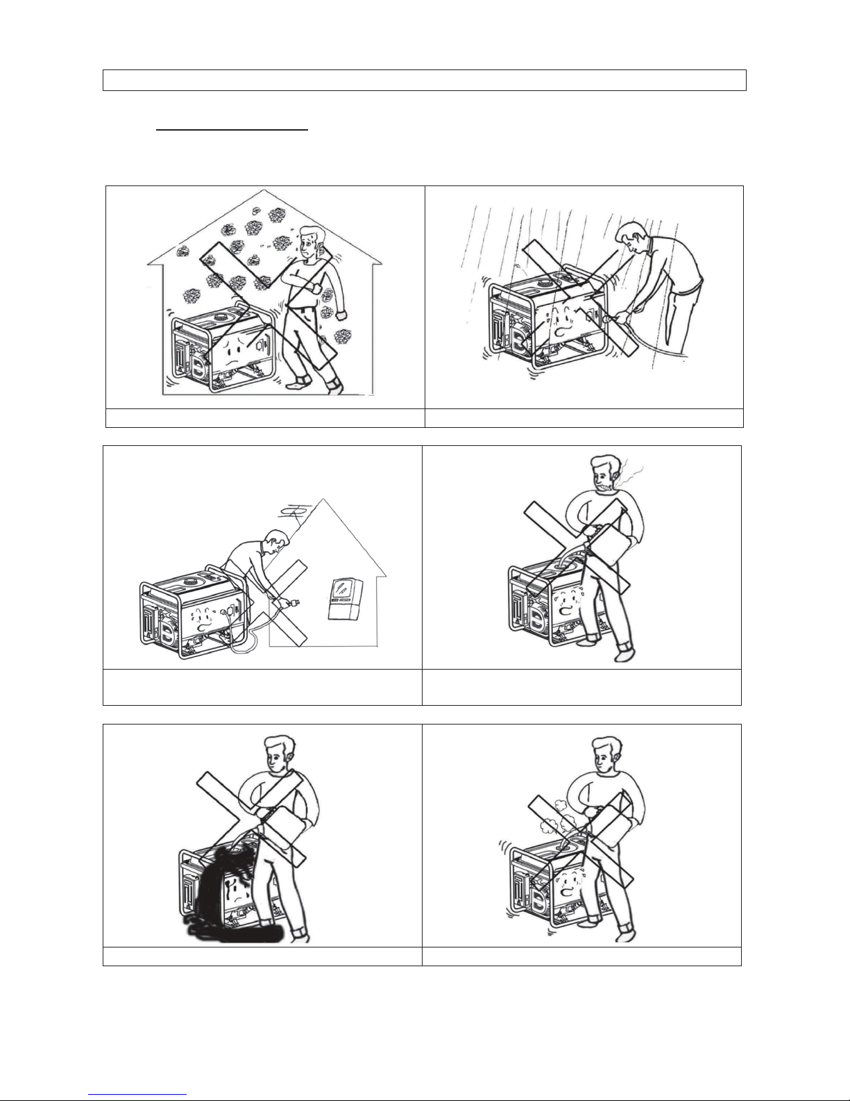
SAFETY NOTICE
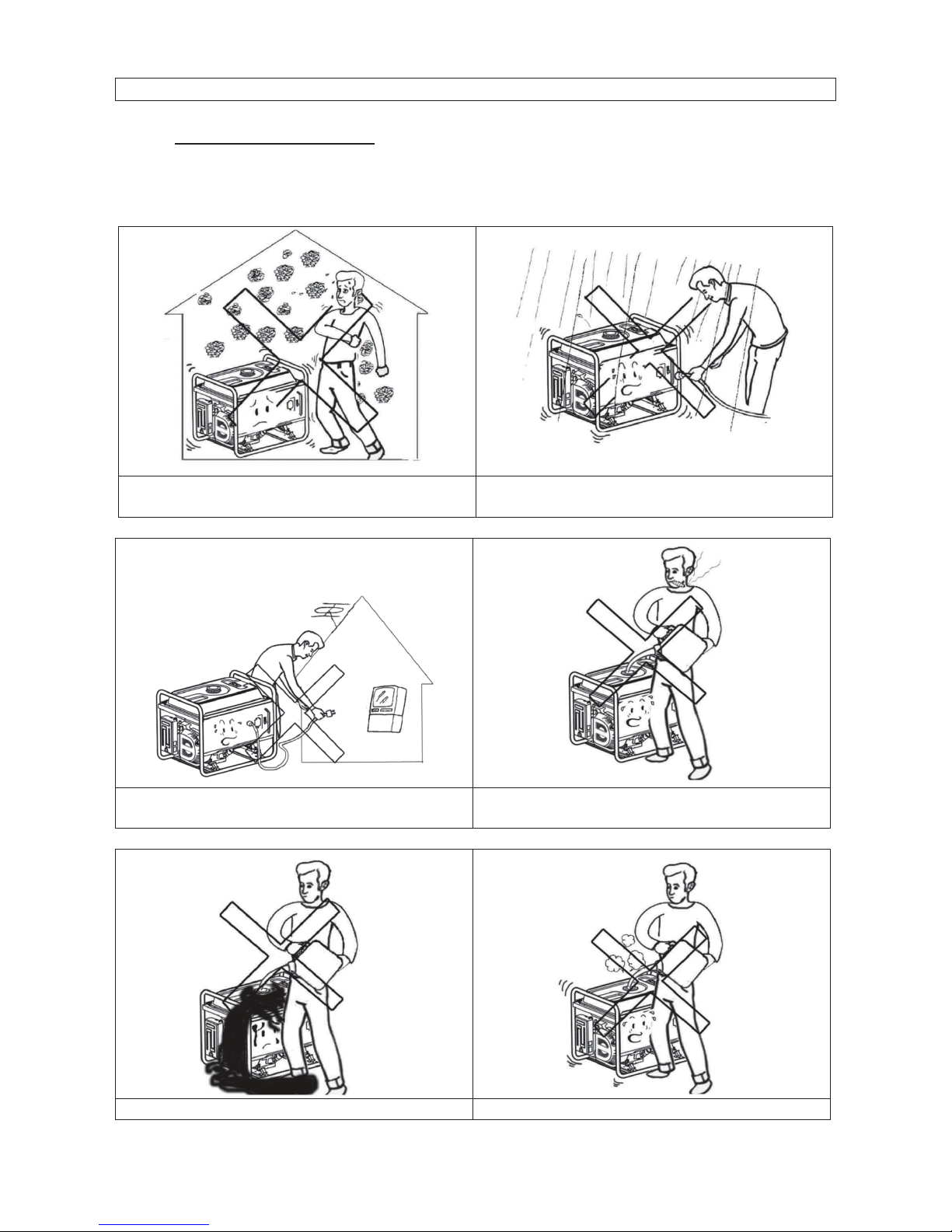
1. SAFETY STANDARD
Read and understand this owner’s manual before starting and operating your generator.
You can help prevent accidents by being familiar with your generator’s controls, and by
observing safe operating procedures.
Don’t operate indoors.
Don’t operate in the wet condition
Don’t directly connect to the household
power supply
Don’t smoke when refuelling
Don’t overflow the fuel when refuelling.
Stop the engine before refuelling
5
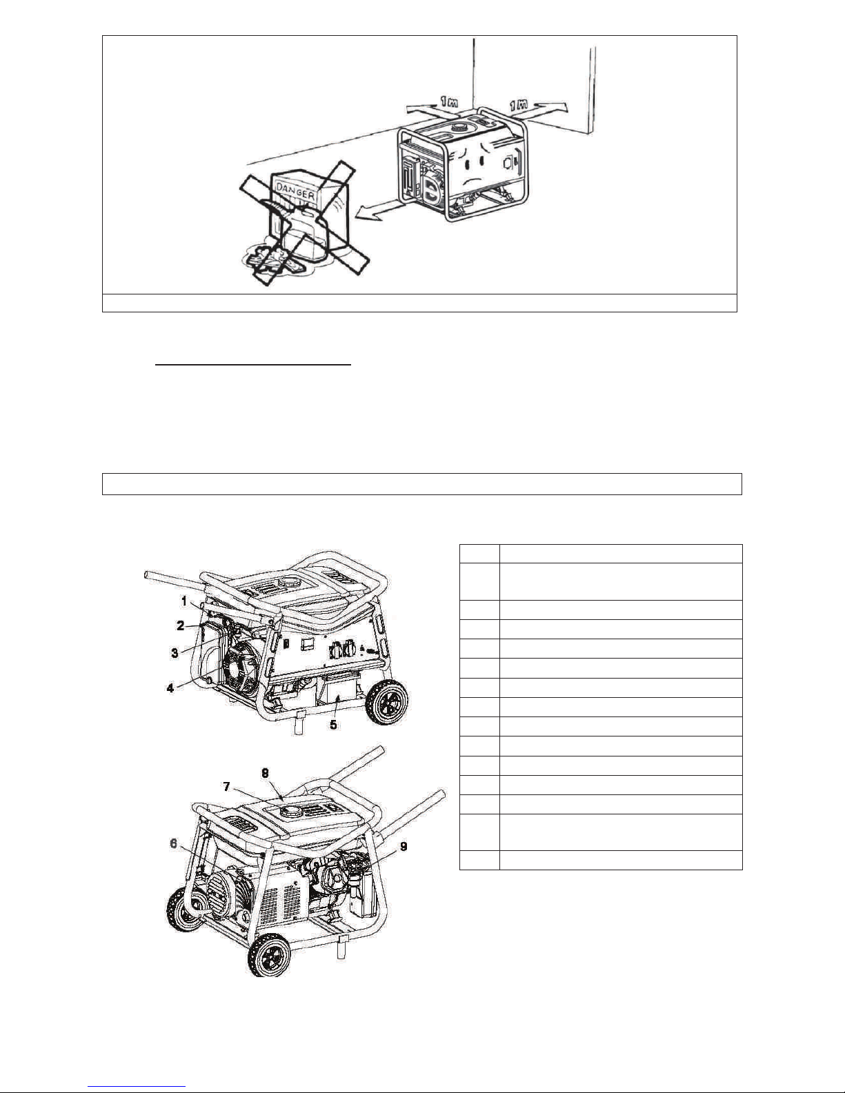
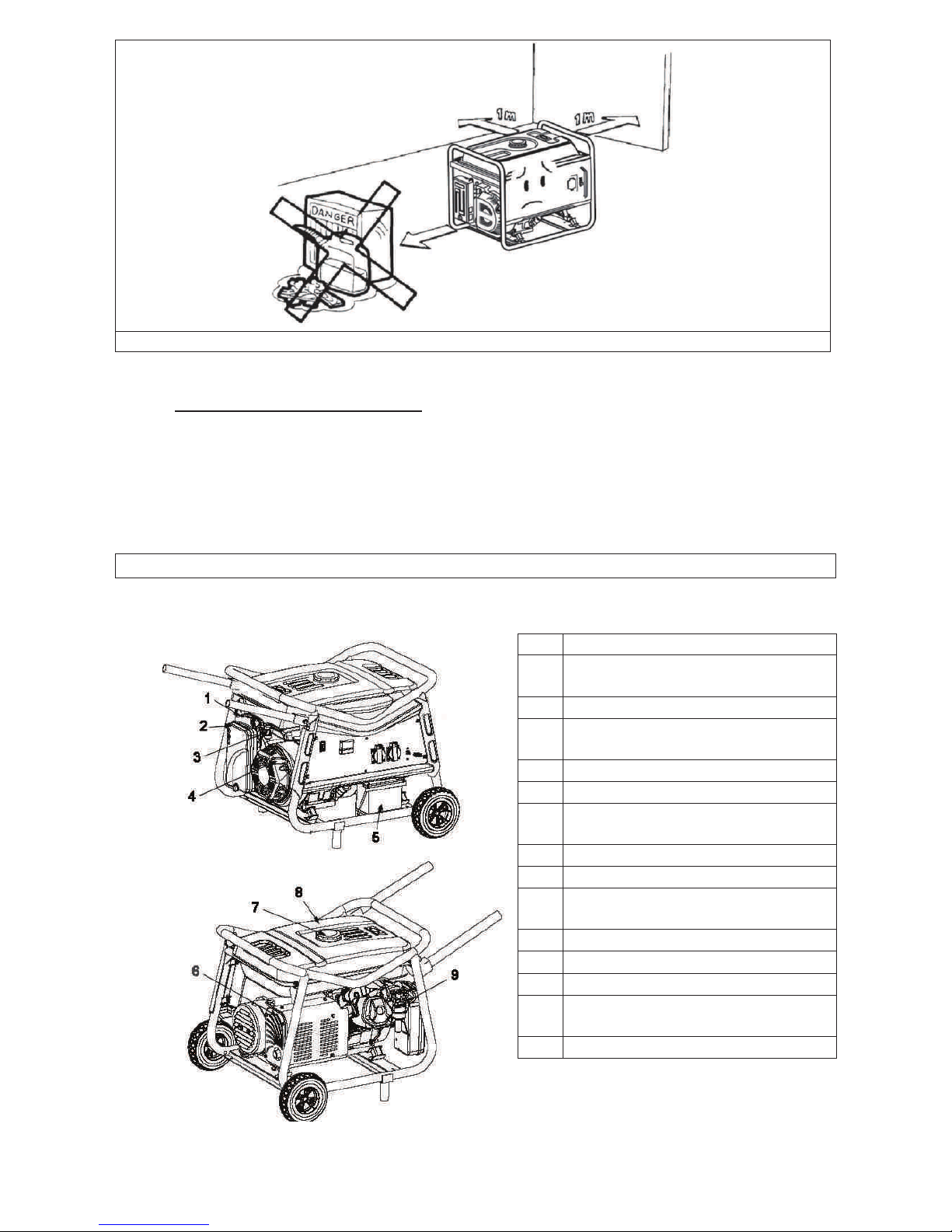
Please keep it 1m minimum away from the inflammable materials
2. SPECIAL REQUIREMENTS
· Electrical equipment including lines and plug connections should be free from
exposure.
· The circuit breakers should be matched with the generator equipment. If the circuit
breakers require replacement, they must be replaced with a circuit breaker having
identical ratings and performance characteristics
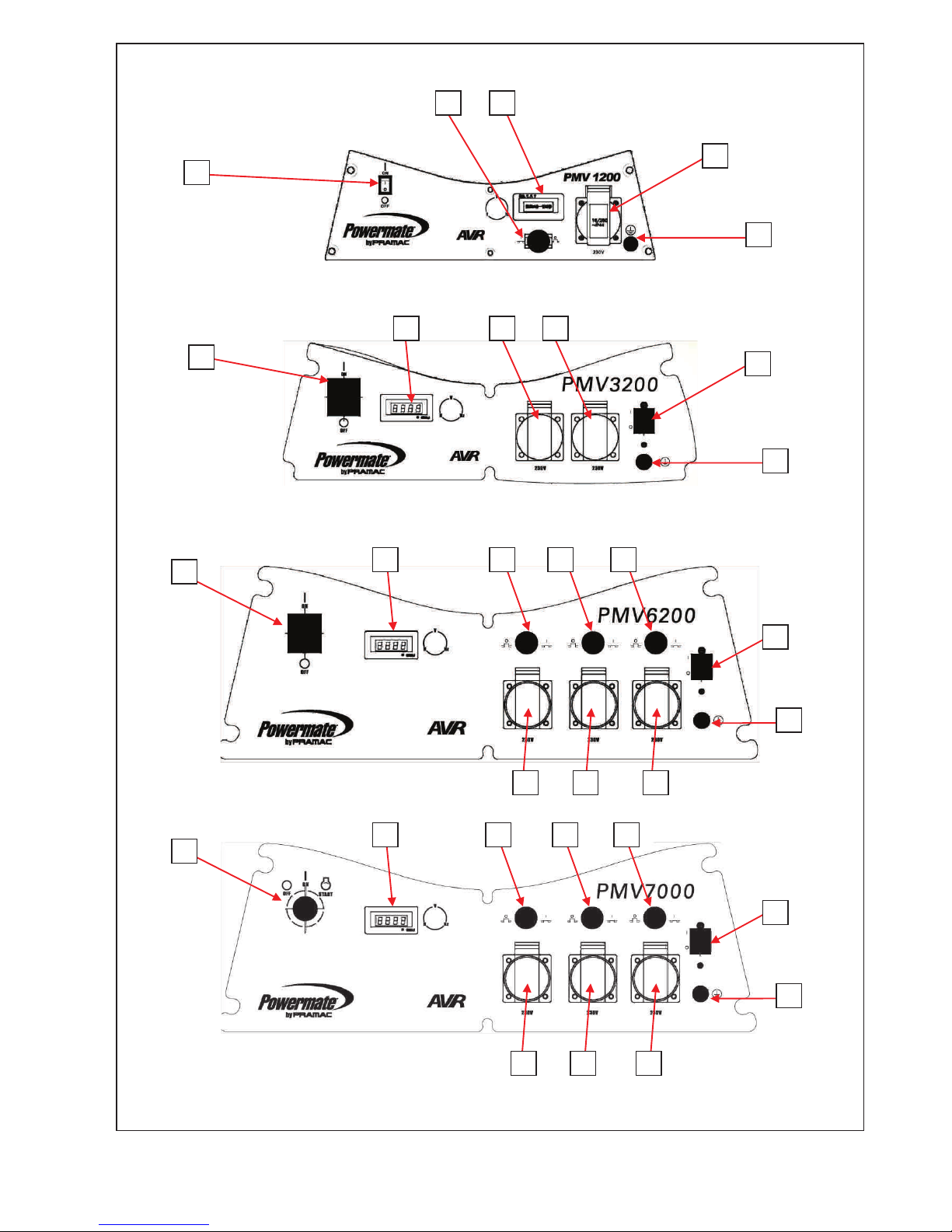
COMPONENT IDENTIFICATION
1
CHOKE LEVER
2
AIR CLEANER
3
FUEL VALVE
4
RECOIL-STARTER GRIP
5
BATTERY (PMV7000)
6
MUFFLER
7
FUEL TANK CAP
8
FUEL TANK
9
CARBURETOR
10
GENERATOR SWITCH
11
CIRCUIT BREAKER
12
SOCKET CIRCUIT BREAKER
13
SCHUKO SOCKETS
14
HOUR METER – VOLT METER
– FREQUENCY METER
15
GROUND TERMINAL
6
10
11
14
13
15
14
13
13
11
15
10
10
14
12
12
12
11
15
13
13
13
14
12
12
12
11
15
10
13
13
13
7
CONTROL
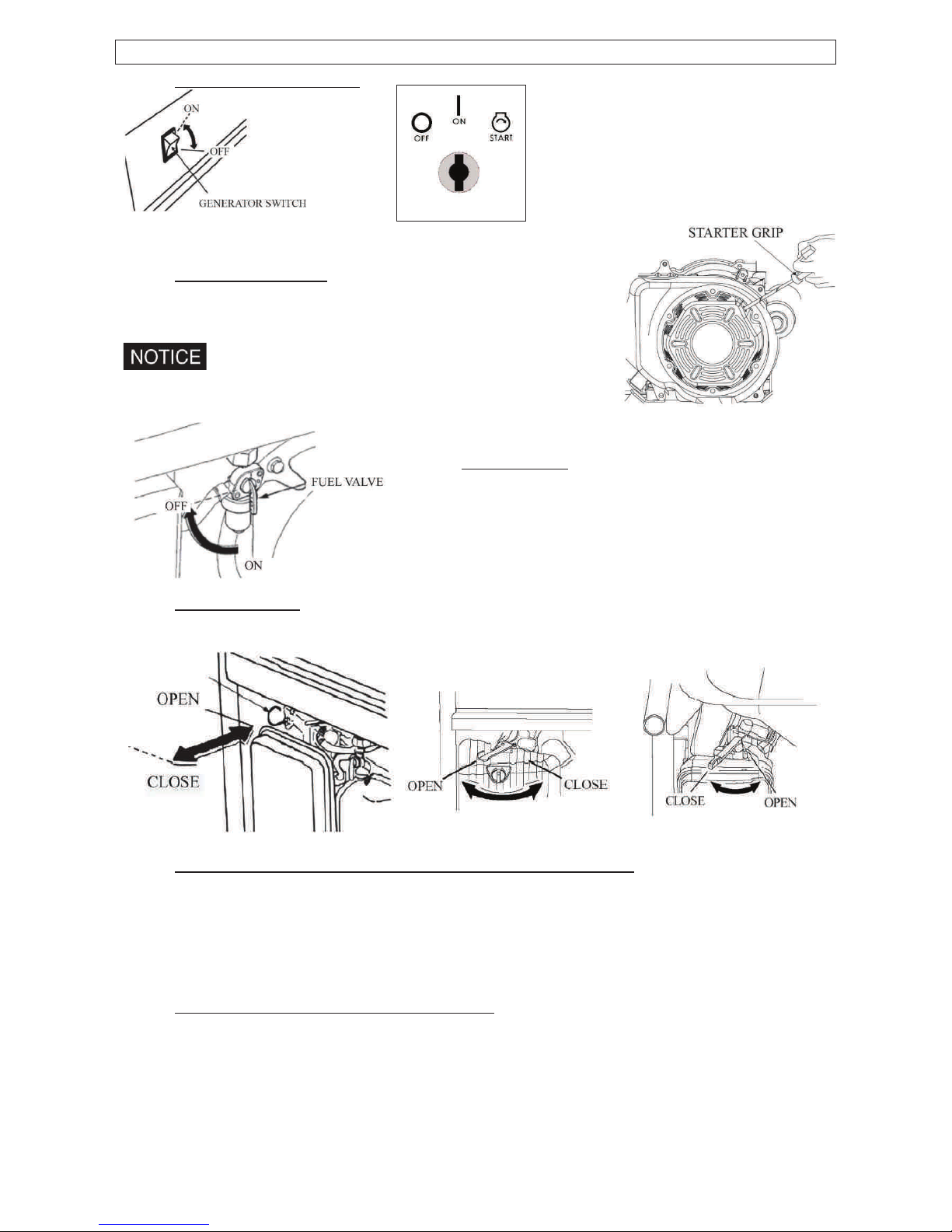
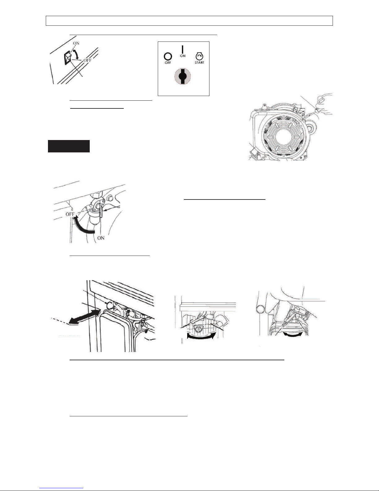
1. GENERATOR SWITCH
2. RECOIL STARTER
To start the engine, pull the starter grip lightly until resistance
is felt, then pull briskly.
Do not allow the starter to snap back against the engine.
Return it gently to prevent damage to the starter.
3. FUEL VALVE
The fuel valve controls fuel flowing from the fuel tank
to carburetor. Be sure to return the lever to “OFF”
after stopping the engine.
4. CHOKE LEVER
The choke lever is used to provide an enriched fuel mixture when starting a cold engine.
Slowly put the choke lever to “OPEN” position after the engine is heated.
5. AC CIRCUIT BREAKER / OVERCURRENT PROTECTIOR
The overload current will automatically switch off circuit breaker to avoid short circuit of the
load or overload. If the indicator of AC Overcurrent Protector is raised, the Over-current
Protector is now in the “OFF” position. Press the button of AC Over-current Protector to
the “ON” position again a few minute later. If the circuit breaker is switched OFF
automatically, switch the circuit breaker ON again.
6. OIL ALERT SYSTEM (Except PMV1200)
The oil alert system is specially designed to prevent engine damage caused by an
insufficient amount of oil in the crankcase. When the oil level in the crankcase falls down
below a safe limit, the oil alert system will automatically shut down the engine (though the
generator switch still remain in the ON position), so that the engine can’t be damaged
resulting from the insufficient amount of the oil.
8
GENERATOR OPERATION
Generator operation environment:·
Temperature:-15Ԩ㹼40Ԩ·
Humidity: 95% lower.·
Height above sea level: 1000 m lower (If the area is 1000 m over, the power should be
lowered in operation).
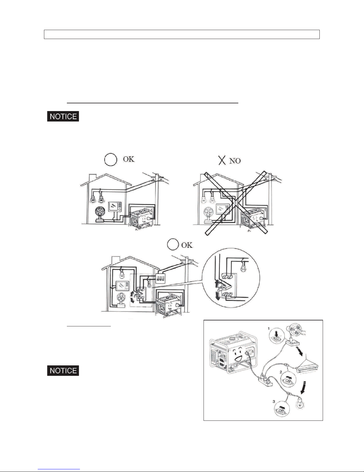
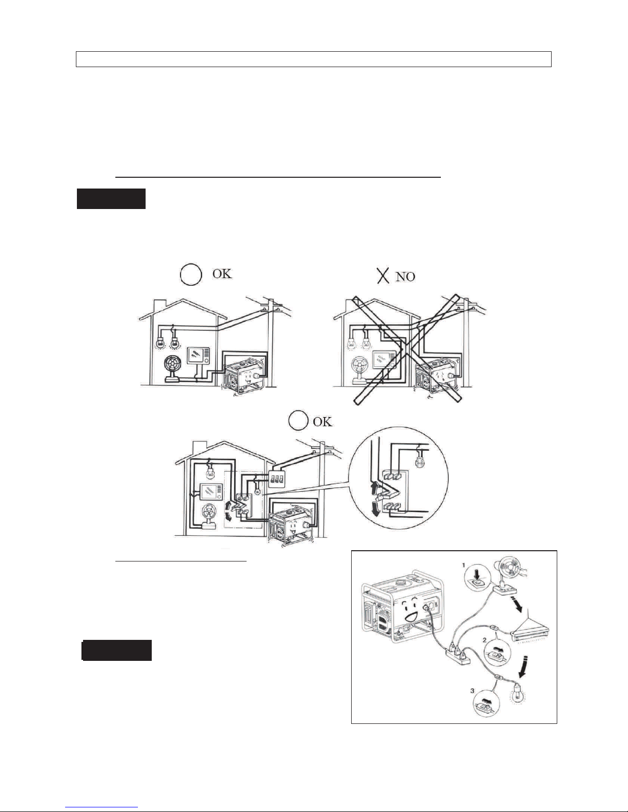
1. CONNECTION TO THE HOUSEHOLD POWER SUPPLY
When connecting the generator to the household power supply, connection must be
made by a qualified electrician. After connecting, carefully check electric
connections for their safety and reliability.
Unsafe connections will result in generator damage and risk of fire.
2. AC CURRENT
Before starting the generator, make sure that total
load appliance power (Total resistance, capacitive
and inductive) does not exceed rated power of the
generator
Overload operation will greatly shorten
generator service life.
If the generator set is connected to multi- loads or
electric appliances, please first connect to current
maximum, in turn, current second, and final,
current minimum.
9
In general, capacitive and inductive load, especially, motor-driven devices have a big
starting current when starting.
3. HIGH ALTITUDE OPERATION
At high altitude, the standard carburetor air-fuel mixture will be excessively rich. Output
power will decrease, and fuel consumption will increase. Engine performance can be
improved by installing a smaller diameter main fuel jet in the carburetor and readjusting the
pilot screw. If you always operate the engine at altitudes above sea level 1000 meters,
have our company authorized dealer perform this carburetor modification. If not, lower load
power in operating generator.
Even equipped with suitable carburetor, engine horsepower will decrease approximately
3.5% for each 300 meter increase in altitude. The effect of altitude on horsepower will be
lowered greater than this if no carburetor modification is made.
If a carburetor for high altitude is equipped with engine suitable to a lower altitude,
the lean air fuel mixture will cause the engine output power lowering, over-heat and
seriously damage.
PRE-OPERATION CHEK
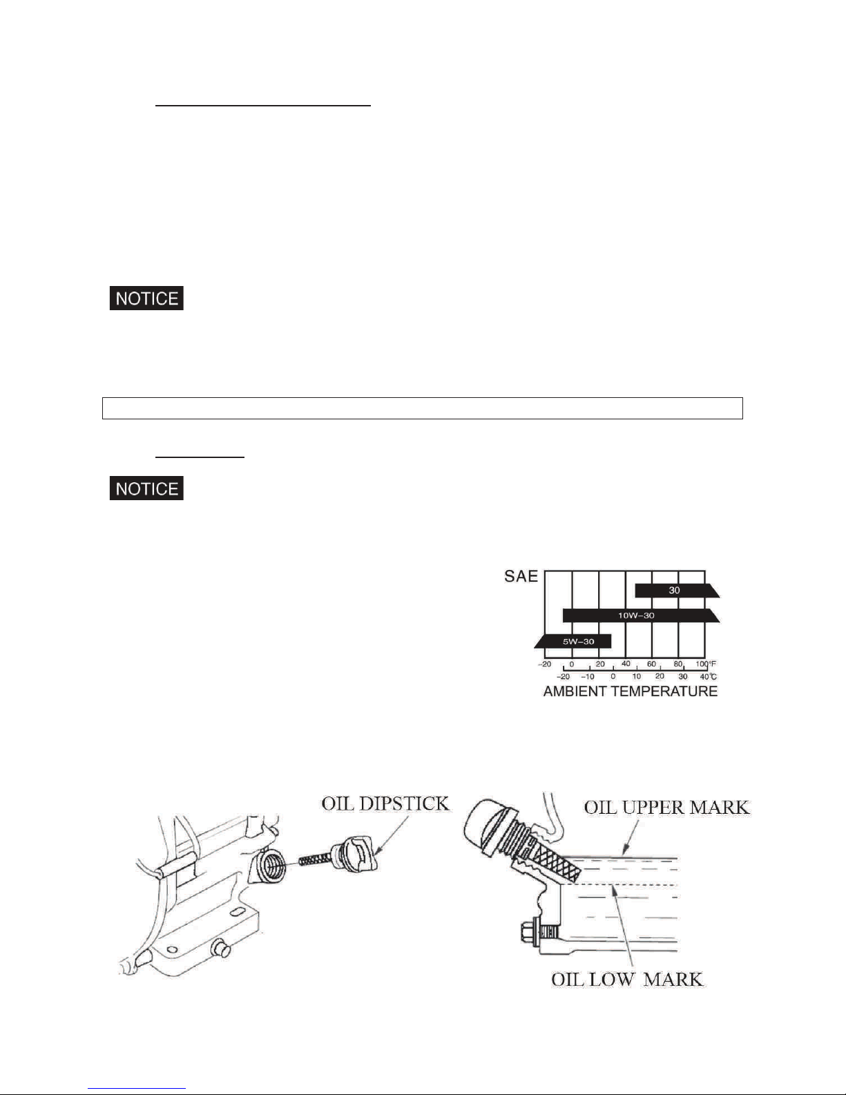
1. ENGINE OIL
Engine oil is a major factor affecting engine performance and service life. Nondetergent and 2-stroke engine oils will damage the engine and are not
recommended. Check the oil level before each use with the generator on a level
surface with the engine stopped.
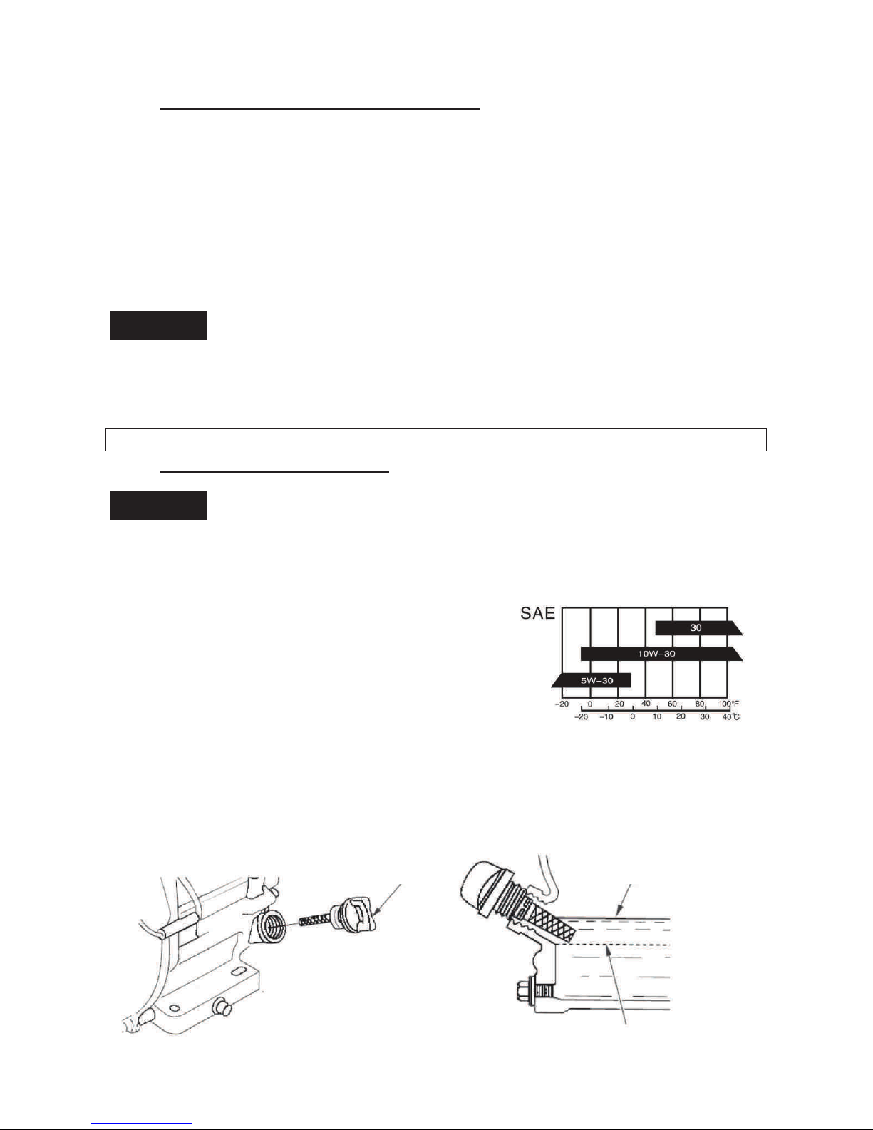
Recommended oil
4-stroke gasoline oil
API service Classification's SF
or SAE10W-30 of equivalent SG class.
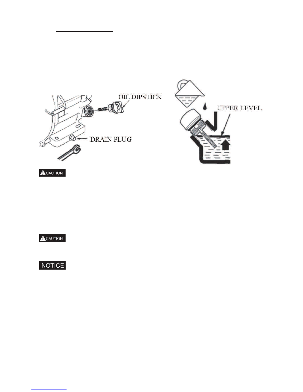
Method of check oil level:
Remove the oil filler cap and wipe the dipstick clean.
Check the oil level by inserting the dipstick into the filler neck without screwing it in.
If the level is low, add the recommended oil to the upper mark on the dipstick.
After adding, don’t forget to reinsert and screw down the oil dipstick.
10
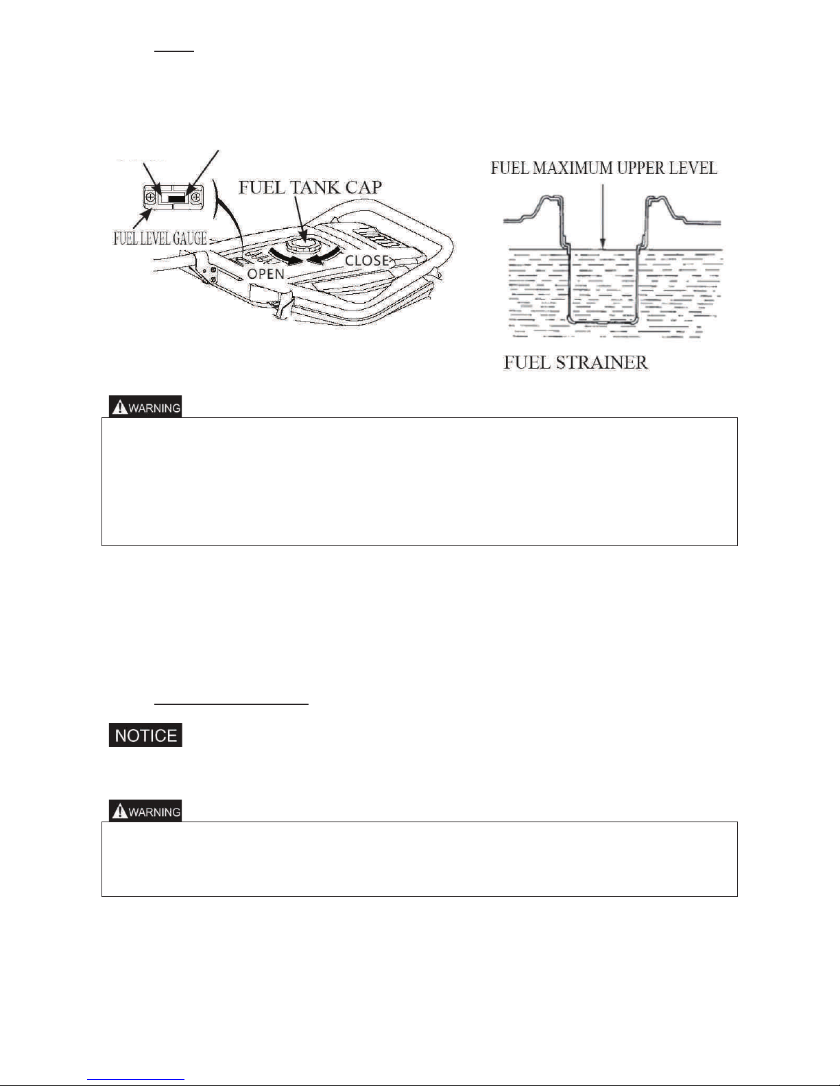
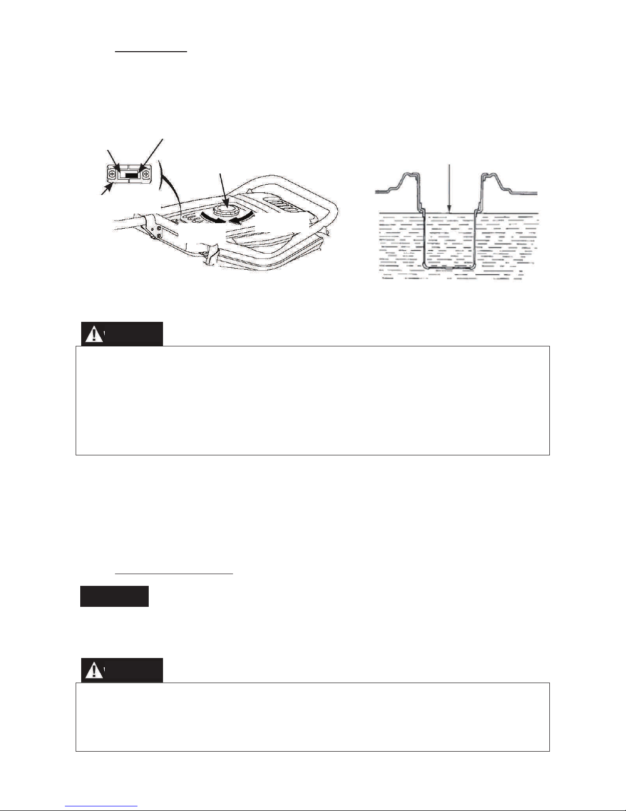
2. FUEL
1. Check the fuel level gauge,
2. Refill the tank if the fuel level is low. Do not fill above the shoulder of the fuel strainer.
3. Reinstall and screw down the fuel tank cap after refuelling.
• Refuel in a well-ventilated area with the engine stopped. Do not smoke or allow
flames or sparks in the area where the engine is refuelled or where gasoline is
stored.
• Do not overfill the fuel tank.
• Avoid repeated or prolonged contact with skin or breathing of vapour.
• Keep out of reach of children.
• Don’t use the oil and gasoline mixture or gasoline contained impurity.
Use gasoline with octane rating ≥90 .
We recommend unleaded gasoline because it produces fewer engine and spark plug
deposits and extends exhaust system life.
Never use stale or contaminated gasoline or oil/gasoline mixture. Avoid getting dirt or
water in the fuel tank.
3. BATTERY (PMV7000)
Don’t connect the battery positive and negative poles in reverse. Reversed
connection can seriously damage the generator set and battery.
• If operated improperly, the battery may be explosive and potentially hurt others
nearby. Keep the fire and inflammable materials far away from battery.
• The battery will release the explosive gas, please keep the fire far away from
battery. Keep the air ventilating when battery is charging and using.
EMPTY
FULL

11
STARTING THE ENGINE
1. RECOIL STARTER
1. Remove all the loads out of the output.
2. Turn the fuel valve to the “ON” position.
3. Turn the AC circuit breaker to the “OFF” position.
4. Turn the choke lever to the “CLOSE” position.
Don’t close the choke when starting the engine in warm state
5. Turn the generator switch to the “ON” position.
6. Pull the starter grip until compression is felt, then pull briskly.
7. Turn the choke lever to the “OPEN” position after the engine is warm.
8. Don’t use electric apparatus before setting circuit breaker to the “ON” position.
2. ELECTRIC STARTING (PMV7000)
1. Remove all the loads out of the output.
2. Turn the fuel valve to the “ON” position.
3. Turn the choke lever to the “CLOSE” position.
Don’t close the choke when starting the engine in warm state.
4. Turning the generator switch to electric starting position.
5. After starting engine, immediately release generator switch and generator switch can
automatically return to open position.
6. Turn the choke lever to “OPEN” position after the engine is warm.
Turn the generator switch to electric starting position for more than 5 seconds can
damage the starting motor. If failing to start, release the switch and wait 10 seconds
before operating it again.
If the speed of the starting motor drops fast after a period of time, it means that the
battery should be recharged.
STOPPING THE ENGINE
1. Turn the AC circuit breaker to the OFF position.
2. Turn the generator switch to the OFF position.
3. Turn the fuel valve to the OFF position.
To stop the engine in an emergency, turn the generator switch to the OFF position.

12
MAINTENANCE
Good maintenance is essential for safe, economical, and trouble-free operation. It will also
help reduce air pollution.
Exhaust gas contains poisonous carbon monoxide. Shut off the engine before
performing any maintenance. If the engine must be run, make sure the area is well
ventilated.
Periodic maintenance and adjustment is necessary to keep the generator in good
operating condition. Perform the service and inspection at the intervals shown in the
Maintenance schedule below:
1. Service more frequently when used in dusty areas.
2. These items should be serviced by an authorized generator dealer.
3. When used more often, only servicing according to above correct intervals can
insure the generator set long-term use.
Improper maintenance, or failure to correct a problem before operation, can cause a
malfunction in which you can be seriously hurt or killed.
Always follow the inspection and maintenance recommendations and schedules in
this owner’s manual.
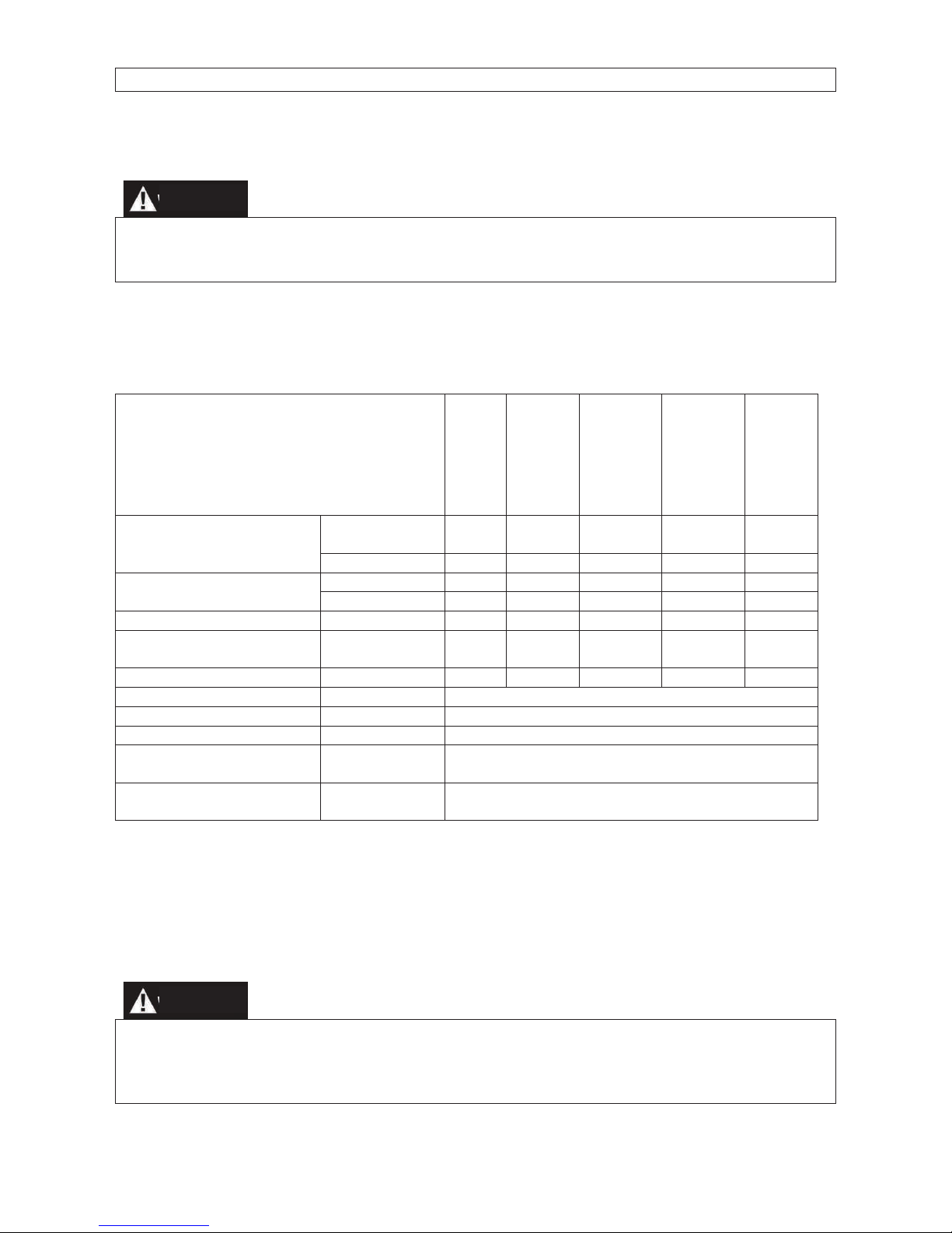
REGULAR SERVICE PERIOD
Each
Use
First
Month
or 20
Hrs.(3)
Every
3
Months
or 50
Hrs. (3)
Every
6
Months
or 100
Hrs. (3)
Every
Year
or 300
Hrs.
(3)
Engine oil
Check Level
○
Change
○ ○
Air cleaner
Check ○
Clean
○ (1)
Sediment Cup
Clean ○
Spark plug
Clean ○
renew
Valve clearance
Check-Adjust
○ (2)
Cylinder Cover
Clean
Every 300 Hours (2)
Fuel tank and strainer
Clean
Every 2 Years (2)
Fuel line
Replace
Every 2 Years (2)
PMV1200–PMV3200
Cylinder head and the
head of piston
Clean carbon
Every 125 hours (2)
PMV6200–PMV7000
Cylinder head and the
head of piston
Clean carbon
Every 250 hours (2)
13
1. ENGINE OIL CHANGE
Drain the oil while the engine is warm to assure complete and rapid draining.
1. Remove the oil dipstick and drain plug to drain the oil.
2.Reinstall the drain plug, then tighten the plug securely.
3. Refill oil and check the oil level.
Oil capacity: PMV1200: 0.3L;
PMV 3200-PMV6200: 0.6L;
PMV7000 1.1L
Refer to the oil security card.
Dispose of the oil according to the local requirements
2. AIR CLEANER SERVICE
A dirty air cleaner will restrict air flow to the carburetor. To prevent carburetor malfunction,
service the air cleaner regularly. Service more frequently when operating the generator in
extremely dusty areas.
Using gasoline or flammable solvent to clean the filter element can cause a fire or
explosion. Use only soapy water or non flammable solvent.
Never run the generator without the air cleaner. If not, rapid engine wear will result.
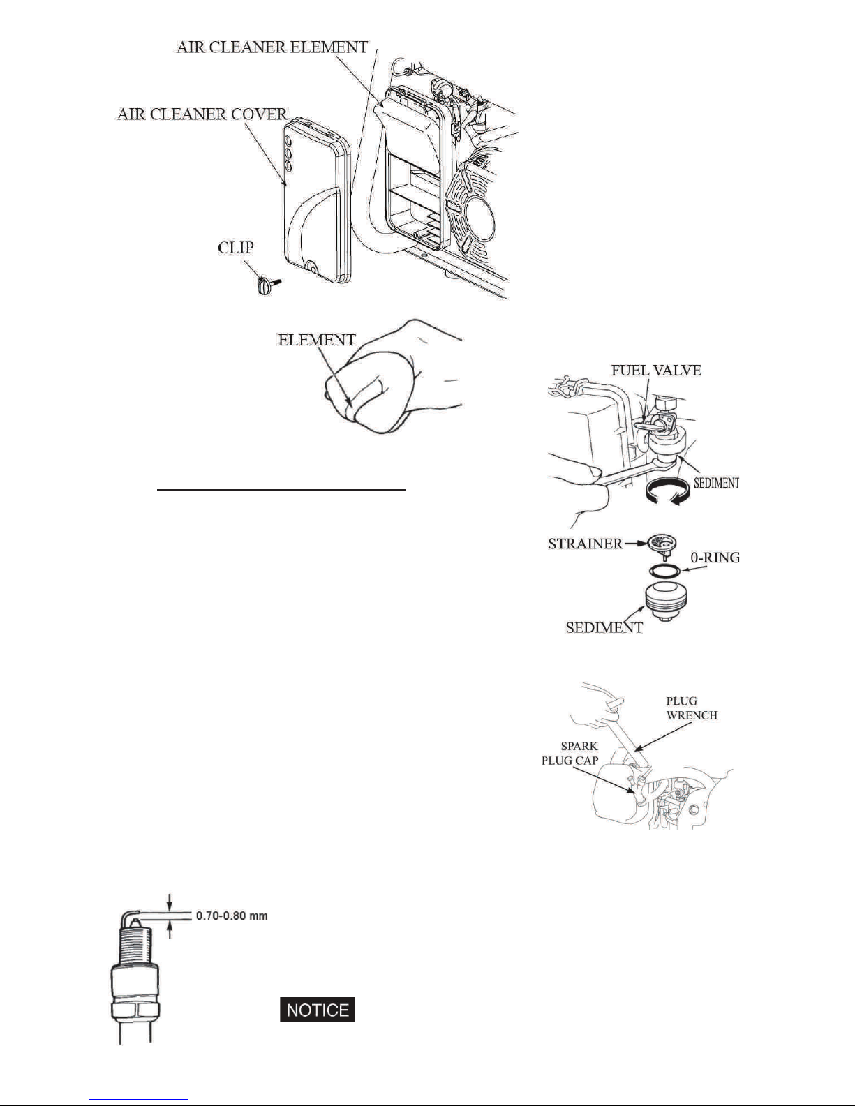
1. Open the air cleaner clip and open the air cover. Check the air cleaner element for
any damage and clean.
2. If the air cleaner element is dirty, please clean the air cleaner element: Wash the
air cleaner element in a solution of household detergent and warm water, then rinse
thoroughly or wash in non flammable or high flash point solvent: Pour a few drops
of engine oil, on the oil filter element then squeeze out.
14
3. Reinstall the air cleaner element and the cover.
3. FUEL SEDIMENT CUP CLEANING
1. Turn the fuel valve to the OFF position. Remove the
sediment cup, o-ring and strainer according to the
arrow direction.
2. Clean the sediment cup, and o-ring, and strainer in
non flammable or high flash point solvent.
3. Reinstall o-ring, and strainer and screw down the
sediment cup.
4. Turn the fuel valve ON and check for leaks.
4. SPARK PLUG SERVICE
1. Recommended spark plugs: F7RTC or other
equivalents
2. Remove the spark plug cap.
3. Use the plug wrench to remove the spark plug.
4. Visually inspect the spark plug if the insulator is
cracked. If cracked, replace with new the spark plug.
5. Measure the plug gap with a feeler gauge. Correct as
necessary by carefully bending the side electrode. The
gap should be: 0.70-0.80 mm.
6. Check the spark plug washer for damage.
7. Reinstall the spark plug, tighten it with plug wrench and impact the washer. Reinstall
the spark plug accurately.
Please use the spark plug with suitable heat range.
15
STORAGE
Do not touch a hot engine or exhaust system to avoid burns or fires. Let the engine
cool before storing the generator.
If storing the unit for an extended period, be sure the storage area is free of excessive
humidity and dust.
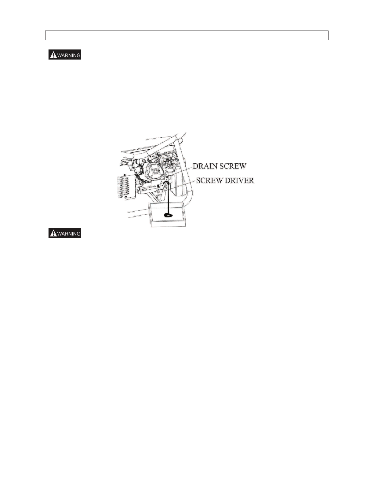
1. Drain the fuel in the fuel tank out, clean strainer, o-ring and sediment cup, then
reinstall. Drain fuel out of the carburettor by loosening the drain screw, then
reinstall and screw down the carburetor screw.
Gasoline is extremely flammable and is explosive under certain conditions. Drain
fuel in a well ventilated area with the engine stopped. Do not smoke or allow flames
or sparks in the area during this procedure.
2. Screw the oil dipstick off and screw the drain bolt off the crankcase to completely
drain the oil out. Then screw down the drain bolt and fill fresh oil to upper mark,
finally reinstall the oil dipstick.
3. Remove the spark plug, and pour about a tablespoon of clean engine oil into the
cylinder. Crank the engine several revolutions to distribute the oil, then reinstall the
spark plug.
4. Slowly pull the starter grip until resistance is felt. Leave the intake and exhaust
valves in the closed position.
5. Place the generator in the clean area.
16
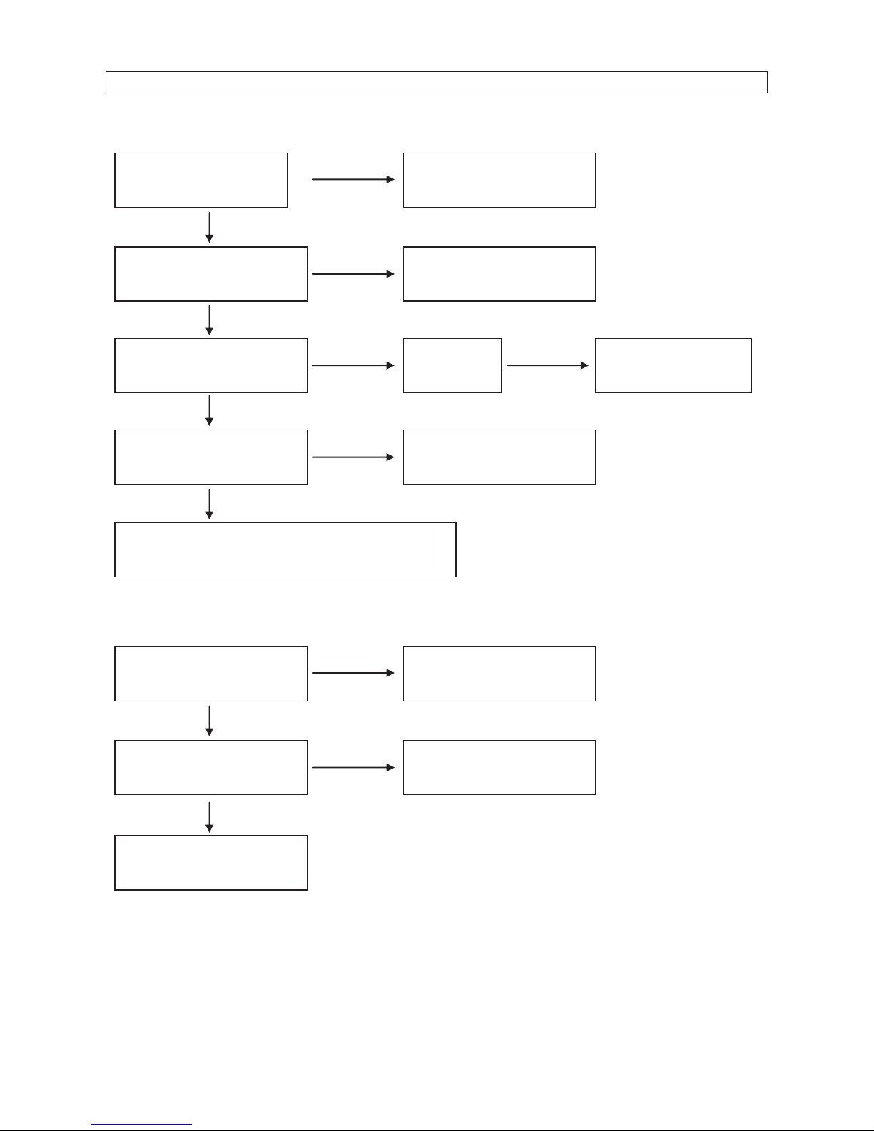
TROUBLESHOOTING
ENGINE UNABLE TO START:
NO POWER SUPPLY:
Is there fuel in the tank?
Refill the fuel tank.
Is there enough oil in the
engine?
Add the recommended oil.
Is there a spark from the
spark plug?
Replace the
spark plug
Take the generator to
an aut
h
orized dealer.
Is the fuel reaching the
carburetor
?
Check and clean the fuel
sediment cup.
If the engine still does not start, take the
generator to an aut
h
orized generator dealer.
NO
NO
NO
NO
Still NO
spark
YES
YES
YES
YES
Is the AC circuit breaker
ON?
Turn the AC circuit
breaker ON.
Check the electrical
appliance or equipment for
any defects.
Take the generator to an
aut
horized dealer.
NO
NO
YES
Replace the electrical
appliance or equipment.
YES
17
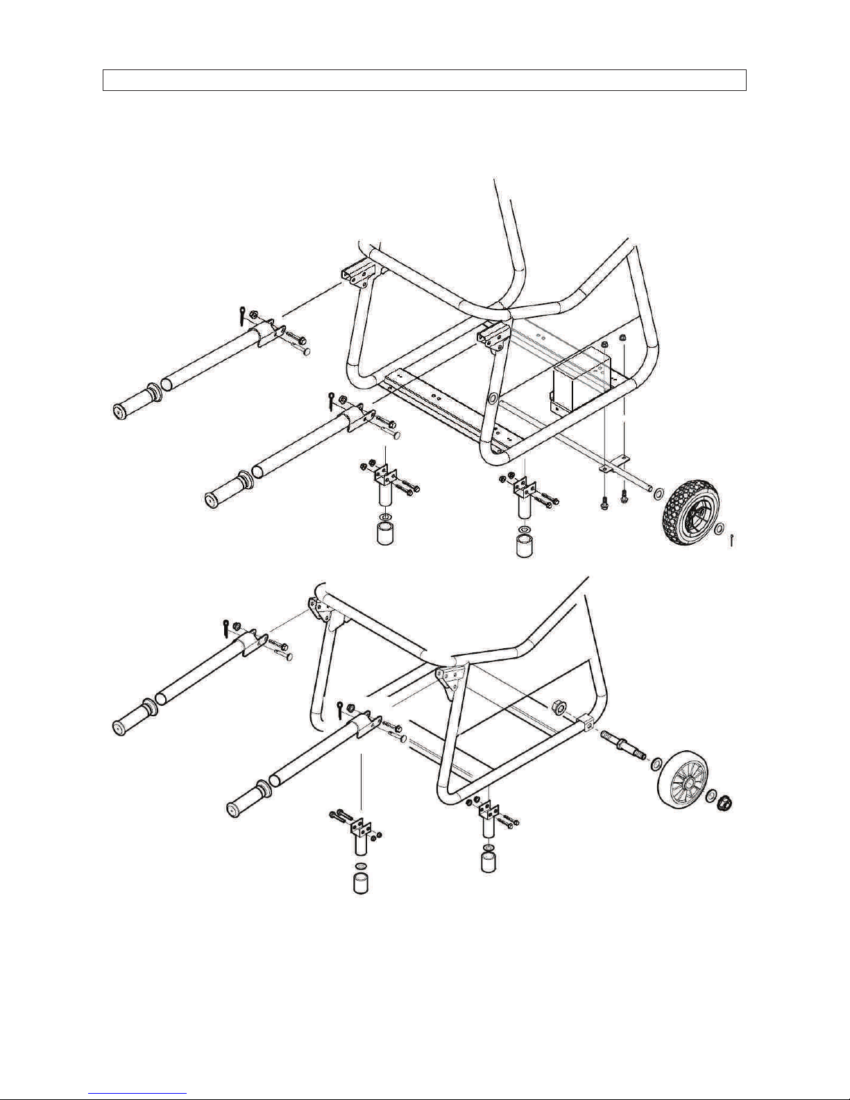
WHEEL KIT – PMV3200 – PMV6200 – PMV7000
1. Install the two wheels on the wheel axle with gaskets and pins.
2. Install the wheel on the bottom plate of the generator frame with bolts and nuts.
3. Fix the handle on the frame.
18
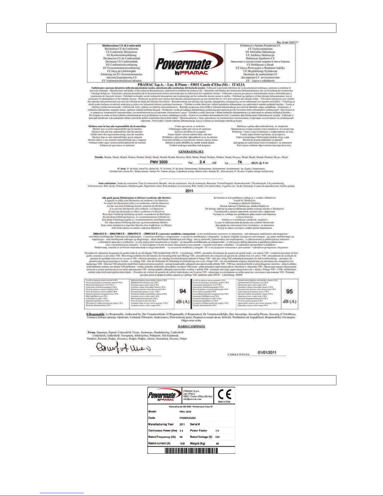
CE DELARATION
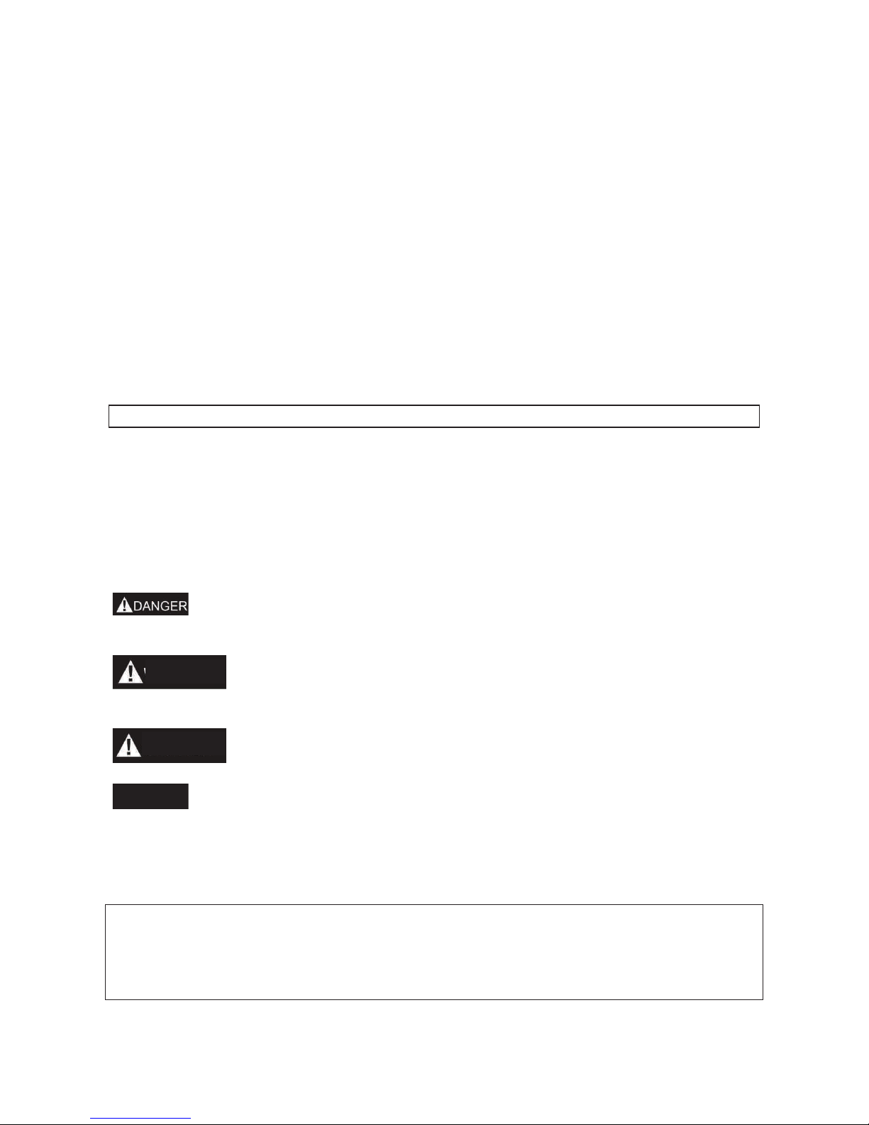
SERIAL NUMBER PLATES

Manuel de l’utilisateur
PMV 1200
PMV 3200
PMV 6200
PMV 7000 (Batterie)
20
Nous vous remercions pour avoir choisi un groupe électrogène de notre société.
Ce manuel contient toutes les informations nécessaires à l’utilisation de celui-ci. Veuillez le
lire attentivement avant toute utilisation. Une utilisation conforme et qui respecte les
normes de sécurité vous aidera à obtenir les meilleurs résultats.
Toutes les informations contenues dans ce manuel correspondent aux dernières
informations sur le produit disponibles au moment où ce manuel passe sous presse. Elles
peuvent par conséquent être quelques peu différentes par rapport aux composants
effectifs de nos groupes à la suite de révisions ou d’autres modifications.
Notre société se réserve le droit d’apporter toute modification, à tout moment, sans aucun
avis préalable et sans qu’aucune obligation ne lui soit faite en ce sens. Toute reproduction,
même partielle, de ce document est interdite sans le consentement écrit de notre société.
Le présent manuel doit être considéré comme une partie intégrante du groupe électrogène
et devra toujours accompagner ce dernier, même en cas de revente.
MESSAGES DE SÉCURITÉ
Votre sécurité ainsi que celle des autres sont très importantes. Nous fournissons
d’importants messages de sécurité dans ce manuel ainsi que sur le groupe électrogène.
Veuillez lire ces messages très attentivement.
Un message de sécurité avertit des risques potentiels de blessures de l’utilisateur ou de
toute autre personne. Tout message de sécurité est précédé d'un symbole de sécurité
d'alerte et d'un de ces trois mots: DANGER, AVERTISSEMENT, ou ATTENTION. Ces
termes signifient:
BLESSURES MORTELLES ou GRAVES BLESSURES si vous ne
respectez pas les instructions.
Risques de BLESSURES MORTELLES ou de GRAVES BLESSURES
si vous ne respectez pas les instructions.
Risques de BLESSURES si vous ne respectez pas les instructions.
Risque d’abîmer votre groupe électrogène ou tout autre équipement si
vous ne respectez pas les instructions.
ADDRESSE DU FABRICANT:
PRAMAC S.p.A.
Loc. Il Piano
CAP 53031, Casole D’Elsa (SI)
ITALIE
AVERTISS.
ATTENTION
NOTA

21
SOMMAIRE
AVIS DE SÉCURITÉ ...............................................................................................................................................22
REPÉRAGE DES COMPOSANTS ........................................................................................................................23
ORGANES DE COMMANDE .................................................................................................................................25
FONCTIONNEMENT DU GROUPE ÉLECTROGÈNE ........................................................................................26
VÉRIFICATIONS AVANT LA MISE EN SERVICE ..............................................................................................27
MISE EN MARCHE DU MOTEUR .........................................................................................................................29
ARRÊT DU MOTEUR .............................................................................................................................................29
ENTRETIEN .............................................................................................................................................................30
REMISAGE ..............................................................................................................................................................33
RECHERCHE DE PANNES ...................................................................................................................................34
KIT DES ROUES – PMV3200 – PMV6200 – PMV7000 ......................................................................................35
DÉCLARATION CE ................................................................................................................................................36
PLAQUETTES NUMÉROS DE SÉRIE .................................................................................................................36
22
AVIS DE SÉCURITÉ
1. NORMES DE SÉCURITÉ
Avant de mettre en marche votre groupe électrogène, il est nécessaire de lire et
comprendre parfaitement toutes les informations et les manoeuvres. Vous préviendrez les
accidents en connaissant bien les organes de commande de votre groupe et en
respectant les procédures opérationnelles.
Ne jamais utiliser le groupe à l’intérieur.
Ne jamais utiliser le groupe en milieu
humide
Ne jamais connecter le groupe directement
à une prise domestique
Ne jamais fumer en faisant le plein
Ne jamais déborder en faisant le plein.
Arrêter le moteur avant de refaire le plein
23
Garder le groupe à au moins 1m de tout matériel inflammable
2. EXIGENCES PARTICULIÈRES
· Le matériel électrique, dont les prises et les fils, doit être intact et ne pas présenter
de câbles dénudés.
· Les disjoncteurs thermiques et magnétothermiques doivent être spécialement
prévus pour le groupe électrogène. Si ces derniers doivent être remplacés, ils
doivent l’être par des disjoncteurs ayant des valeurs nominales et des
caractéristiques identiques.
REPÉRAGE DES COMPOSANTS
1
MANETTE DU STARTER
2
FILTRE À AIR
3
VANNE DU CARBURANT
4
POIGNÉE DU LANCEUR
RÉENROULEUR
5
BATTERIE (PMV7000)
6
SILENCIEUX
7
BOUCHON RÉSERVOIR
CARBURANT
8
RÉSERVOIR CARBURANT
9
CARBURATEUR
10
CONNECTEUR GROUPE
ÉLECTROGÈNE
11
DISJONCTEUR
12
DISJONCTEUR PRISE
13
PRISES SCHUKO
14
HOROMÈTRE – VOLTMÈTRE –
FRÉQUENCEMETRE
15
PRISE DE TERRE

24
10
11
14
13
15
14
13
13
11
15
10
10
14
12
12
12
11
15
13
13
13
14
12
12
12
11
15
10
13
13
13
25
ORGANES DE COMMANDE
1. CONTACTEUR DU GROUPE ÉLECTROGÈNE
2. POIGNÉE DU LANCEUR
RÉENROULEUR
Pour le démarrage, saisir la poignée du lanceur puis tirer
lentement jusqu’à rencontrer une légère résistance. Tirer
ensuite par un mouvement court et sec.
Ne pas lâcher brusquement la poignée du lanceur pour
éviter qu’il ne cogne brusquement contre le moteur.
Accompagner l’enroulement pour éviter d’endommager le lanceur.
3. VANNE DU CARBURANT
La vanne de carburant contrôle le passage du
carburant du réservoir vers le carburateur. Faire
attention à bien mettre sur “OFF” la manette après
avoir arrêté le moteur.
4. MANETTE DU STARTER
La manette du starter a été prévue pour fournir un mélange de carburant enrichi lorsqu’on
démarre avec le moteur à froid. Tirer lentement la manette du starter en position “OPEN”
après réchauffement du moteur.
5. DISJONCTEUR C.A. / PROTECTION CONTRE LES SURCHARGES
Tout courant de surcharge déclenche immédiatement le disjoncteur pour éviter tout courtcircuit et toute surcharge. Si l’indicateur de surcharge C.A. intervient, le protecteur de
surcharge passe à la position “OFF”. Remettre le bouton du protecteur de surcharge C.A.
sur la position “ON” quelques minutes après. Si le disjoncteur s’éteint (OFF)
automatiquement, le rallumer (ON).
6. SÉCURITE D'HUILE (Sauf PMV1200)
Cette sécurité a été spécialement conçue pour prévenir tout dégât au moteur à cause d’un
manque d’huile dans le bloc moteur. Lorsque le niveau d’huile dans ce dernier descend en
dessous d’un certain seuil, la sécurité d'huile arrête le moteur (même si l’interrupteur du
groupe électrogène reste allumé (ON)) et ce, afin d’éviter tout dégât au moteur à cause
d’un niveau d'huile insuffisant.
NOTA
CONTACTEUR GROUPE
ÉLECTROGÈNE
POIGNÉE DU LANCEUR
VANNE DU
CARBURANT
OUVERT
OUVERT
OUVERT
FERME
FERME
FERME
26
FONCTIONNEMENT DU GROUPE ÉLECTROGÈNE
Environnement pour le fonctionnement du groupe:
Température:-15Ԩ㹼40Ԩ·
Degré hygrométrique: moins de 95%·
Altitude s/m: moins de 1000 m (si le lieu d’utilisation se trouve à plus de 1000 m, la
puissance sera diminuée au cours du fonctionnement).
1. CONNEXION AU RÉSEAU DE DISTRIBUTION DOMESTIQUE
La connexion du groupe électrogène au réseau de distribution domestique sera
uniquement effectuée par un électricien qualifié. La connexion effectuée, en vérifier
le bon état et les conditions de sécurité en l'absence desquelles le groupe
générateur pourrait subir des dégâts, brûler ou être la source d'un incendie.
2. COURANT ALTERNATIF
Avant de mettre le groupe électrogène en marche,
vérifier que la charge totale de l’appareil
(Résistance totale, capacitive et inductive) n’est
pas supérieure à la charge nominale du groupe
électrogène.
Tout fonctionnement en conditions de
surcharge risque de réduire considérablement
la durée de vie de votre groupe électrogène.
Si vous devez alimenter plusieurs charges
simultanément, vous devez d’abord connecter la charge plus importante lourde puis les
autres jusqu’à la plus faible.
NOTA
NOTA
27
En général, les engins motorisés avec charge capacitive et inductive, surtout, présentent
une charge élevée au démarrage.
3. FONCTIONNEMENT EN HAUTE ALTITUDE
En haute altitude, le mélange carburé du carburateur est trop riche. La puissance
dégagée diminue et la consommation de carburant grimpe. On peut améliorer les
performances du moteur en installant un gicleur principal de plus petit diamètre sur le
carburateur et en réglant la vis pilote. Si le moteur fonctionne toujours à des altitudes de
1000 mètres au-dessus du niveau de la mer, demandez à un revendeur autorisé de notre
société d'effectuer cette modification sur le carburateur. Sinon, vous obtiendrez moins de
charge pendant le fonctionnement du groupe électrogène.Car même si vous avez un
carburateur adéquat, la puissance de votre moteur baissera d’environ 3.5% à chaque
élévation de hauteur de 300 m. L'impact de l'altitude sur la puissance dégagée se fera
sentir davantage si aucune modification n'est apportée au carburateur.
Si le carburateur qui est utilisé à hauteur élevée est équipé d’un moteur convenant
aux basses altitudes, le maigre mélange carburé sera à l'origine d'une diminution de
la puissance dégagée par le moteur, ce qui provoquera une surchauffe et des
dégâts sérieux.
VÉRIFICATIONS AVANT LA MISE EN SERVICE
1. NIVEAU D'HUILE DU MOTEUR
L’huile moteur est un élément essentiel pour les bonnes performances et la
longévité de votre groupe électrogène. Les huiles moteur non détergentes et 2
temps endommageront le moteur et sont dès lors à déconseiller. Avant chaque
démarrage vérifier le niveau d'huile moteur. La
vérification se fera le groupe posé sur une
surface horizontale avec moteur arrêté.
Huile conseillée
Huile pour moteur essence 4 temps
API Service classe SF
ou SAE10W-30 ou classe SG équivalente.
Méthode pour vérifier le niveau d’huile:
Retirer le bouchon de remplissage et essuyer la jauge de niveau. Contrôler le niveau
d’huile en introduisant la jauge dans le col de remplissage sans la visser.
Si le niveau d’huile est bas, faire l’appoint jusqu’au cran supérieur de la jauge.
Après avoir fait l’appoint, n’oubliez pas de remettre la jauge en place et de la revisser.
NOTA
NOTA
TEMPÉRATURE AMBIANTE
AUGE D’HUILE
CRAN HUILE SUPÉRIEUR
CRAN HUILE INFÉRIEUR
28
2. CARBURANT
1. Contrôler l’indicateur de niveau de carburant.
2. Faire le plein si le niveau de carburant est bas. Ne pas dépasser le niveau de l’épaule
du décanteur.
3. Après avoir fait le plein, remettre le bouchon de remplissage et le visser.
• Faire le plein dans un endroit bien aéré et avec moteur à l’arrêt. Ne pas fumer ou
approcher de flammes vives ou d’étincelles près du lieu où le plein est effectué ou
près du lieu de stockage du carburant.
• Ne pas trop remplir le réservoir.
• Éviter tout contact prolongé avec la peau ou toute respiration prolongée des
vapeurs.
• Ne pas garder à la portée des enfants.
• N’utiliser que de l’huile ou un mélange d’essence propres, sans impuretés.
Utiliser de l’essence à ≥90 octanes.
Nous conseillons l’essence sans plomb qui produit moins de dépôts au niveau du moteur
et de la bougie et qui assure une meilleure longévité du système d’échappement.
Ne jamais utiliser de l’huile ou un mélange huile/essence contaminé ou usé. Eviter toute
présence d’eau ou de dépôts dans le réservoir.
3. BATTERIE (PMV7000)
Respectez les polarités: ne jamais invertir les bornes positives et négatives des
batteries en les montant. Une inversion peut entraîner de graves dégâts sur
l’équipement et la batterie.
• En cas de mise en marche non conforme, la batterie peut exploser et blesser
quiconque se trouve à proximité. Ne jamais placer la batterie à proximité d’une
flamme ou de matériel inflammable.
• La batterie dégage des gaz explosifs. Ne jamais placer la batterie à proximité d’un
feu. Garder le milieu bien aéré lorsque vous chargez ou utilisez la batterie.
PLEIN
VIDE
INDICATEUR NIVEAU
OUVER
FERME
NIVEAU MAXIMAL CARBURANT
DECANTER CARBURANT
BOUCHON RÉSERVOIR CARBURANT
AVERTISS.
NOTA
AVERTISS.

29
MISE EN MARCHE DU MOTEUR
1. LANCEUR RÉENROULEUR
1. Enlever toute charge.
2. Mettre la vanne de carburant sur la position “ON”.
3. Tourner le disjoncteur C.A. sur “OFF”.
4. Tourner la manette du starter sur la position “FERMÉ”.
Ne fermez jamais le starter lorsque vous mettez le moteur en marche à chaud
5. Placer le contacteur du groupe électrogène sur la position “ON”.
6. Saisir la poignée du lanceur puis tirer lentement sur celle-ci jusqu’à sentir une certaine
résistance puis tirer avec un coup vif.
7. Lorsque le moteur est chaud, mettre la manette du starter sur la position “OPEN”.
8. N’utilisez jamais d’appareils électriques avant de mettre le disjoncteur sur la position
ON.
2. MISE EN MARCHE ÉLECTRIQUE (PMV7000)
1. Enlever toute charge.
2. Mettre la vanne de carburant sur la position “ON”.
3. Mettre la manette du starter sur la position “FERMÉ”.
Ne fermez jamais le starter lorsque vous mettez en marche le moteur à chaud.
4. Tourner le contacteur du groupe électrogène à la position Mise en marche électrique.
5. Après la mise en marche du moteur, libérer immédiatement le contacteur du groupe
électrogène; ce dernier retournera automatiquement à la position ‘ouvert’.
6. Mettre la manette du starter à la position “OUVERT” après que le moteur est chaud.
Mettre le contacteur du groupe électrogène sur la position Mise en marche
électrique pendant plus de 5 secondes peut endommager le démarreur. S’il ne
démarre pas, libérez le contacteur et attendre 10 secondes avant de remettre en
marche.
Si la vitesse du démarreur baisse après un certain temps, il faut recharger la
batterie.
ARRÊT DU MOTEUR
1. Mettre le disjoncteur C.A. sur la position OFF.
2. Mettre le contacteur du groupe électrogène sur la position OFF.
3. Mettre la vanne de carburant sur la position OFF.
Pour arrêter le moteur d’une façon urgente, placer le contacteur du groupe
électrogène sur la position OFF.
NOTA
NOTA
NOTA
NOTA
30
ENTRETIEN
Un bon entretien est une condition essentielle pour un fonctionnement en toute sécurité,
économique et sans problèmes. Il réduit également l’impact sur la pollution de l’air
ambiant.
Les gaz d’échappement contiennent du monoxyde de carbone qui est toxique.
Éteignez toujours le moteur avant d’effectuer tout entretien. Si le moteur doit
tourner, assurez-vous que l’environnement dans lequel il se trouve est bien aéré.
Un entretien et des mises au point ponctuels sont nécessaires si vous voulez conserver
votre groupe électrogène dans de bonnes conditions de fonctionnement. Pour la
fréquence de l’entretien et les opérations à effectuer, voir le programme d’entretien qui
suit:
1. Les intervalles d’entretien seront plus courts si le groupe électrogène est utilisé
dans un environnement poussiéreux.
2. L’entretien sera effectué par un revendeur autorisé de groupes électrogènes.
3. En cas d’utilisation plus fréquente, un entretien effectué avec les intervalles
indiqués ci-dessus assurera une utilisation à long terme de votre groupe
électrogène.
Tout entretien non conforme ou ne pas résoudre un problème avant la mise en
marche peut être la source de dysfonctionnements qui risque de provoquer de
blessures graves, voire mortelles.
Toujours respecter les consignes d’entretien et de contrôle données dans ce livret.
P
ÉRIODE D’ENTRETIEN RÉ
GULIER
A
chaq
ue
utilisa
tion
Premie
r mois
ou 20
heures
.(3)
Tous les
3 mois
ou
50
heures
(3)
Tous les
6 mois
ou
1
00
heures
(3)
Chaqu
e
année
ou
300
heures
(3)
Huile moteur
Vérifier le
niveau
○
Renouveler
○ ○
Filtre à air
Vérifier ○
Nettoyer
○ (1)
Cuvette de sédimentation
Nettoyer
○
Bougie d’allumage
Nettoyer
○
Renouv
eler
Soupape
Vérifier-régler
○ (2)
Couvercle du cylindre
Nettoyer
toutes les 300 heures (2)
Réservoir et décanteur
Nettoyer
tous les 2 ans (2)
Conduit carburant
Remplacer
tous les 2 ans (2)
PMV1200–PMV3200
Culasse et tête du piston
Nettoyer les
charbons
toutes les 125 hours (2)
PMV6200–PMV7000
Culasse et tête de piston
Nettoyer les
charbons
toutes les 250 heures (2)
AVERTISS.
AVERTISS.
 Loading...