

Page 1

Owner’s Manual
2-Gallon Air Compressor
1.0 HP
Oil Free
Model No. SAC22HPP
10/04/2017
Part No. E110923
CAUTION: Before using this product, read this manual and follow all its Safety Rules and
Operating Instructions.
• Safety Instructions
• Installation & Operation
• Maintenance & Storage
• Troubleshooting Guide
• Parts List
• Español, p. 20
• French, p. 42
CALIFORNIA PROPOSITION 65 WARNING: This product contains chemicals known to
the State of California to cause cancer, birth defects and/or reproductive harm.
MAT Industries, LLC
Jackson, TN 38301 U.S.A.
www.powermate.com
Page 2

2- ENG
TABLE OF CONTENTS
Warranty ................................................................2
Safety Symbols ...........................................................3
Important Safety Instructions & Guidelines ......................................3
Hazard ................................................................3-8
Specifications ............................................................8
Glossary ................................................................9
Duty Cycle ..............................................................10
Overview ...............................................................11
Assembly ...............................................................12
Installation ...........................................................13-14
Operating Procedures .....................................................15
Maintenance ............................................................16
Storage ................................................................16
Troubleshooting Guide .................................................17-18
Parts List .............................................................. 19
Spanish ............................................................... 20
French ................................................................ 42
Service Number ...................................................back cover
What Does This Warranty Cover? MAT Industries, LLC. (the Company) warrants from the date of purchase by the original retail purchaser only,
parts and labor to remedy substantial defects found in materials, or workmanship.
How Long Does The Coverage Last? The duration of this warranty is one year. This warranty is not transferable to subsequent owners.
What MAT Industries Will Do: MAT Industries, LLC will cover parts and labor to remedy substantial defects due to materials and workmanship
during the first year of ownership, with the exceptions noted below, and parts only, to remedy substantial defects due to material and
workmanship for the remaining term of coverage with the exceptions noted below. Parts used in repair of whole goods or accessories are
warranted for the balance of the original warranty period.
What is Not Covered Under This Warranty? Failure by the original retail purchaser to install, maintain, and operate said equipment in
accordance with standard industry practices. Modifications to the product, or tampering with components, or failure to comply with the specific
recommendations of the Company set forth in the owner’s manual, will render this warranty null and void. The Company shall not be liable for
any repairs, replacements, or adjustments to the equipment, or any costs for labor performed by the purchaser without the Company’s prior
written approval. The effects of corrosion, erosion, surrounding environmental conditions, cosmetic defects, and routine maintenance items, are
specifically excluded from this warranty. Routine maintenance items such as: oil, lubricants, and air filters, as well as changing oil, air filters, belt
tensioning, etc… fall under the owner’s responsibility. Additional exclusions include: freight damage, failures resulting from neglect, accident, or
abuse, induction motors when operated from a generator, oil leaks, air leaks, oil consumption, leaky fittings, hoses, petcocks, bleeder tubes, and
transfer tubes.
• If the compressor is used for commercial, industrial, or military applications, the warranty will apply for 90 days from the date of
purchase. Two stage compressors are not limited to a 90 day warranty when used in commercial or industrial applications.
• Rental applications render this warranty null and void.
• The following components are considered normal wear items and are not covered after the first year of ownership: Belts, sheaves,
flywheels, check valves, pressure switches, air unloaders, throttle controls, electric motors, brushes, regulators, o-rings, pressure gauges,
tubing, piping, fittings, fasteners, wheels, quick couplers, gaskets, seals, air filter housings, piston rings, connecting rods, and piston seals.
• Labor, service calls, and travel charges, are not covered after the first year of ownership on stationary compressors (compressors without
handles, or wheels). Repairs requiring overtime, weekend rates, or any other charges beyond the standard shop labor rate are not covered.
• Time required for orientation training for the service center to gain access to the product, or additional time due to inadequate egress.
• Damage caused by incorrect voltage, improperly wired, or failure to have a certified licensed electrician install the compressor, will render
this warranty null and void.
• Damage caused from inadequate filter maintenance.
• Pump wear or valve damage caused by using oil not specified.
• Pump wear or damage caused by any oil contamination.
• Pump wear or valve damage caused by failure to follow proper maintenance guidelines.
• Operation below proper oil level or operation without oil.
• Gas Engines, if product is equipped with a gas engine, see engine manual for specific engine manufacturer’s warranty coverage.
Parts purchased separately: The warranty for parts purchased separately such as: pumps, motors, etc., are as follows:
From Date of Purchase
• All single & two stage pumps 1 year
• Electric motors 90 days
• Universal motor/pump 30 days
• All other parts 30 days
• No return authorization will be issued for electrical components once items are installed.
How do You Get Service? In order to be eligible for service under this warranty you must be the original retail purchaser, and provide proof
of purchase from one of MAT Industries dealers, distributors, or retail outlet stores. Portable compressors or components must be delivered,
or shipped, to the nearest Authorized MAT Industries Service Center. All associated freight costs and travel charges must be borne by the
consumer. Please call our toll free number 1-888-895-4549 for assistance.
THIS WARRANTY GIVES YOU SPECIFIC LEGAL RIGHTS, AND YOU MAY ALSO HAVE OTHER RIGHTS WHICH VARY FROM STATE
TO STATE. THE COMPANY MAKES NO OTHER WARRANTY OR REPRESENTATION OF ANY KIND WHATSOEVER, EXPRESSED OR
IMPLIED, EXCEPT THAT OF TITLE. ALL IMPLIED WARRANTIES, INCLUDING ANY WARRANTY OF MERCHANTABILITY AND FITNESS
FOR PARTICULAR PURPOSE ARE HEREBY DISCLAIMED. LIABILITY FOR CONSEQUENTIAL AND INCIDENTAL DAMAGES UNDER
ANY AND ALL WARRANTIES, OTHER CONTRACTS, NEGLEGENCE, OR OTHER TORTS IS EXCLUDED TO THE EXTENT EXCLUSION IS
PERMITTED BY LAW.
MAT Industries, LLC, Jackson, TN 38301 U.S.A.
1 YEAR LIMITED WARRANTY
Page 3
3 - ENG
This manual contains information that is important for you to know and
understand. This information relates to protecting YOUR SAFETY and
PREVENTING EQUIPMENT PROBLEMS. To help you recognize this information,
we use the symbols below. Please read the manual and pay attention to
these symbols.
Indicates an imminently hazardous situation which, if not
avoided, will result in death or serious injury.
Indicates a potentially hazardous situation which, if not
avoided, could result in death or serious injury.
Indicates a potentially hazardous situation which, if not
avoided, may result in minor or moderate injury.
Indicates a practice not related to personal injury which, if not
avoided, may result in property damage.
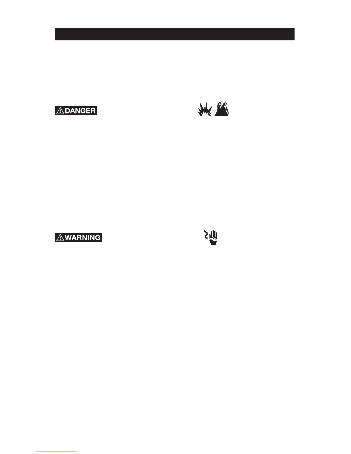
WHAT CAN HAPPEN HOW TO PREVENT IT
• It is normal for electrical
contacts within the motor and
pressure switch to spark.
• Always operate the compressor
in a well ventilated area free
of combustible materials,
gasoline, or solvent vapors.
• If electrical sparks from
compressor come into contact
with flammable vapors, they may
ignite, causing fire or explosion.
• If spraying flammable materials,
locate compressor at least
20' (6.1m) away from spray
area. An additional length of
air hose may be required.
• Store flammable materials
in a secure location away
from compressor.
RISK OF EXPLOSION OR FIRE.
TO REDUCE THE RISK OF INJURY, READ THE
INSTRUCTION MANUAL.
SAFETY SYMBOLS
IMPORTANT SAFETY INSTRUCTIONS
HAZARD
Save these instructions
Page 4
4- ENG
• Restricting any of the compressor
ventilation openings will
cause serious overheating
and could cause fire.
• Never place objects against
or on top of compressor.
• Operate compressor in an open
area at least 12" (30.5 cm) away
from any wall or obstruction that
would restrict the flow of fresh
air to the ventilation openings.
• Operate compressor in a
clean, dry well ventilated area.
Do not operate unit in any
confined area. Store indoors.
• Unattended operation of this
product could result in personal
injury or property damage.
To reduce the risk of fire, do
not allow the compressor
to operate unattended.
• Always remain in attendance with
the product when it is operating.
• Always turn off and unplug
unit when not in use.
RISK TO BREATHING (ASPHYXIATION).
WHAT CAN HAPPEN HOW TO PREVENT IT
• The compressed air directly from
your compressor is not safe for
breathing. The air stream may
contain carbon monoxide, toxic
vapors, or solid particles from the air
tank. Breathing these contaminants
can cause serious injury or death.
• Never use air obtained directly
from the compressor to supply
air for human consumption. The
compressor is not equipped with
suitable filters and in-line safety
equipment for human consumption.
• Exposure to chemicals in dust
created by power sanding,
sawing, grinding, drilling,
and other construction
activities may be harmful.
• Sprayed materials such as paint,
paint solvents, paint remover,
insecticides, weed killers, may
contain harmful vapors and poisons.
• Work in an area with good cross
ventilation. Read and follow
the safety instructions provided
on the label or safety data
sheets for the materials you are
spraying. Always use certified
safety equipment: NIOSH/OSHA
respiratory protection or properly
fit ting face mask designed for use
with your specific application.
HAZARD
Page 5

5 - ENG
WHAT CAN HAPPEN HOW TO PREVENT IT
• Failure to properly drain condensed
water from air tank, causing rust
and thinning of the steel air tank.
• Drain air tank daily or after each use.
If air tank develops a leak, replace
it immediately with a new air tank
or replace the entire compressor.
• Modifications or attempted
repairs to the air tank.
• Never drill into, weld, or make any
modifications to the air tank or its
attachments. Never attempt to
repair a damaged or leaking air
tank. Replace with a new air tank.
• Unauthorized modifications
to the safety valve or any
other components which
control air tank pressure.
• The air tank is designed to withstand
specific operating pressures.
Never make adjustments or
parts substitutions to alter the
factory set operating pressures.
Attachments & accessories:
• Exceeding the pressure rating of air tools, spray guns, air
operated accessories, tires,
and other inflatables can cause
them to explode or fly apart, and
could result in serious injury.
• Follow the equipment manufacturers
recommendation and never exceed
the maximum allowable pressure
rating of attachments. Never use
compressor to inflate small low
pressure objects such as children’s
toys, footballs, basketballs, etc.
NOTE: Air tanks, compressors, and
similar equipment used to inflate
tires can fill small tires like these
very quickly. Adjust the pressure
regulator on the air supply to a value
that does not exceed that of the tire
pressure. Add air gradually and use
the tire pressure gauge frequently
to avoid overinflating them.
RISK OF BURSTING.
NOTICE: On February 26, 2002, the U.S. Consumer Product Safety Commission
published Release # 02-108 concerning air compressor tank safety:
• Air compressor receiver tanks do not have an infinite life. Tank life is
dependent upon several factors, some of which include operating conditions,
ambient conditions, proper installations, field modifications, and the level of
maintenance. The exact effect of these factors on air receiver life is difficult
to predict.
• If proper maintenance procedures are not followed, internal corrosion to the
inner wall of the air receiver tank can cause the air tank to unexpectedly
rupture allowing pressurized air to suddenly and forcefully escape, posing risk
of injury to consumers.
• The air tank of your compressor must be decommissioned at the end of the
year mentioned on the warning label affixed to the tank.
• The following conditions may cause the air tank to deteriorate, and make it
explode violently.
HAZARD
Page 6
6- ENG
WHAT CAN HAPPEN HOW TO PREVENT IT
• Your compressor is powered by
electricity. Like any other electrically
powered device, if it is not used
properly it may cause electric shock.
• Never operate the compressor
outdoors when it is raining
or in wet conditions.
• Never operate compressor
with protective covers
removed or damaged.
• Repairs attempted by unqualified
personnel can result in serious
injury or death by electrocution.
• Any electrical wiring or repairs
required on this product should be
performed by authorized service
center personnel in accordance with
national and local electrical codes.
• Electrical Grounding: Failure to
provide adequate grounding to
this product could result in serious
injury or death from electrocution.
Refer to Grounding Instructions
paragraph in the Installation section.
• Make certain that the electrical
circuit to which the compressor
is connected provides proper
electrical grounding, correct voltage
and adequate fuse protection.
WHAT CAN HAPPEN HOW TO PREVENT IT
• The compressed air stream can
cause soft tissue damage to
exposed skin and can propel dirt,
chips, loose particles, and small
objects at high speed, resulting in
property damage or personal injury.
• Always wear certified safety
equipment: ANSI Z87.1 eye
protection (CAN/CSA Z94.3)
with side shields when
using the compressor.
• Never point any nozzle or sprayer
toward any part of the body or
at other people or animals.
• Always turn the compressor
off and bleed pressure from
the air hose and air tank before
attempting maintenance,
attaching tools or accessories.
RISK OF HOT SURFACES.
RISK OF ELECTRICAL SHOCK.
RISK FROM FLYING OBJECTS.
WHAT CAN HAPPEN HOW TO PREVENT IT
• Touching exposed metal such
as the compressor head, engine
head, engine exhaust or outlet
tubes, can result in serious burns.
• Never touch any exposed metal
parts on compressor during or
immediately after operation.
Compressor will remain hot for
several minutes after operation.
• Do not reach around protective
shrouds or attempt maintenance
until unit has been allowed to cool.
HAZARD
Page 7
7 - ENG
RISK FROM MOVING PARTS.
WHAT CAN HAPPEN HOW TO PREVENT IT
• Moving parts such as the pulley,
flywheel, and belt can cause
serious injury if they come into
contact with you or your clothing.
• Never operate the compressor
with guards or covers which
are damaged or removed.
• Keep your hair, clothing, and
gloves away from moving parts.
Loose clothes, jewelry, or long hair
can be caught in moving parts.
• Air vents may cover moving parts
and should be avoided as well.
• Attempting to operate compressor
with damaged or missing parts or
attempting to repair compressor
with protective shrouds removed
can expose you to moving parts
and can result in serious injury.
• Any repairs required on this product
should be performed by authorized
service center personnel.
HAZARD
RISK OF UNSAFE OPERATION.
WHAT CAN HAPPEN HOW TO PREVENT IT
• Unsafe op er a tion of your
compressor could lead to se ri ous
in ju ry or death to you or others.
• Review and understand all
instructions and warnings
in this manual.
• Be come fa mil iar with the op eration
and con trols of the air compressor.
• Keep operating area clear of all
persons, pets, and obstacles.
• Keep chil dren away from the
air compressor at all times.
• Do not operate the product
when fatigued or under the
influence of alcohol or drugs.
Stay alert at all times.
• Never defeat the safety
features of this prod uct.
• Equip area of operation
with a fire extinguisher.
• Do not op er ate machine
with missing, broken, or
un au tho rized parts.
Page 8
8- ENG
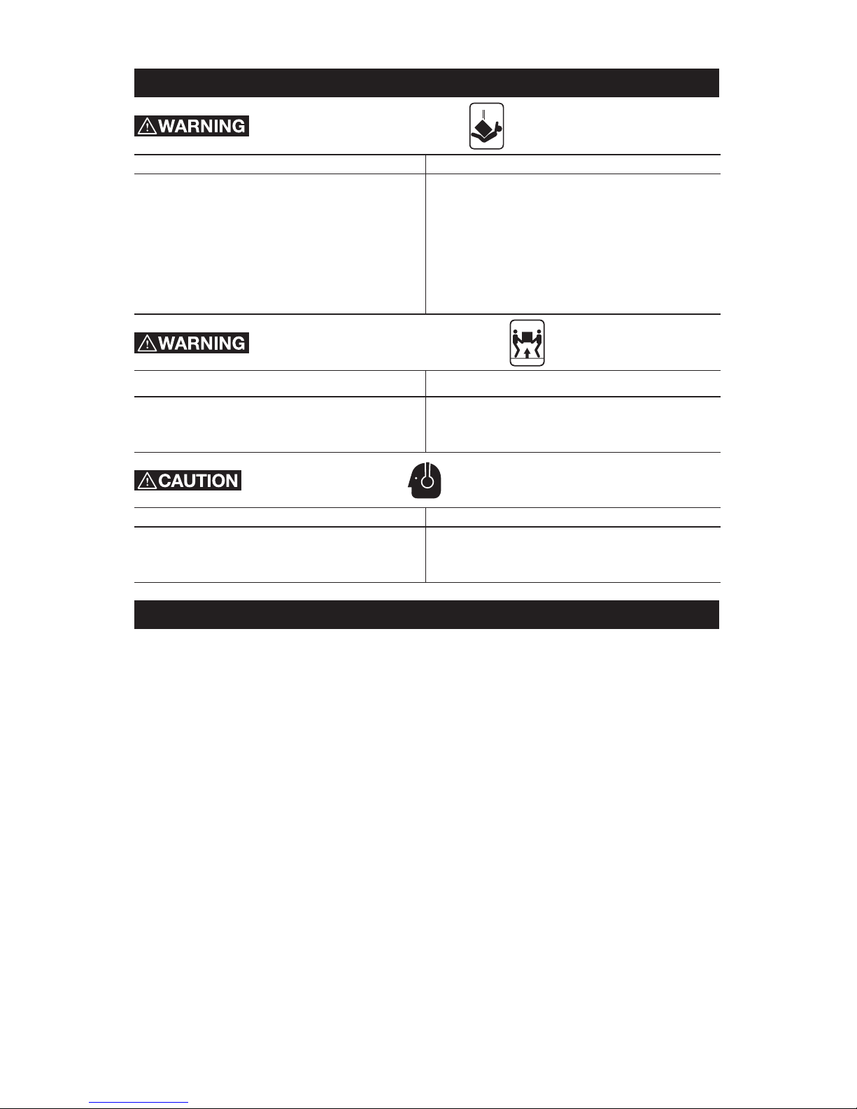
RISK OF INJURY FROM LIFTING.
RISK OF FALLING OBJECT.
WHAT CAN HAPPEN HOW TO PREVENT IT
• A portable compressor can fall
from a table, workbench, or roof
causing damage to the compressor
and could result in serious injury
or death to the operator.
• Always operate compressor in a
stable secure position to prevent
accidental movement of the
unit. Never operate compressor
on a roof or other elevated
position. Use additional air
hose to reach high locations.
WHAT CAN HAPPEN HOW TO PREVENT IT
• Serious injury can result
from attempting to lift
too heavy an object.
• The compressor is too heavy to
be lifted by one person. Obtain
assistance from others before lifting.
RISK FROM NOISE.
WHAT CAN HAPPEN HOW TO PREVENT IT
• Under some conditions and duration
of use, noise from this product
may contribute to hearing loss.
• Always wear certified safety
equipment: ANSI S12.6
(S3.19) hearing protection.
Model No. SAC22HPP
Running Horsepower 1.0 *
Voltage 120
Hz-Single Phase 60
Minimum Branch Circuit Requirement 15 amps
Fuse Type Time Delay
Air Tank Capacity (Gallon) 2 gallons (7.57 liters)
Maximum Air Pressure 125 PSI
Approximate Cut-in Pressure 95 PSIG
Approximate Cut-out Pressure 125 PSIG
SCFM @ 40 PSI 3.0 *
SCFM @ 90 PSI 2.0 *
* Tested per ISO 1217
Refer to Glossary for abbreviations.
HAZARD
SPECIFICATION CHART
Page 9

9 - ENG
GLOSSARY
Air Filter
Porous element contained within a
metal or plastic housing attached to
the compressor cylinder head which
removes impurities from the intake air
of the compressor.
Air Tank
Cylindrical component which contains
the compressed air.
Check Valve
Device that prevents compressed air
from flowing back from the air tank to
the compressor pump.
Cut-in Pressure
The low pressure at which the motor
will automatically restart.
Cut-out Pressure
The high pressure at which the motor
will automatically shut off.
Electric Motor
Device which provides the rotational
force necessary to operate the
compressor pump.
NPT (National Pipe Thread)
A seal thread tape must be used
to provide a leak-free seal on pipe
threaded connections.
Pressure Regulator Knob
Regulates the outgoing pressure from
the air outlet to the tool. It is possible
to increase or decrease the pressure
at the outlet by adjusting this
control knob.
Pressure Switch
Automatically controls the on/off
cycling of the compressor. It stops the
compressor when the cut-off pressure
in the tank is reached and starts the
compressor when the air pressure
drops below the cut-in pressure.The
pressure switch will not automatically
start and control the compressor
unless the manual AUTO/Off Switch is
in the AUTO position.
PSI (Pounds Per Square Inch)
Measurement of the pressure exerted
by the force of the air. The actual PSI
is measured by a pressure gauge
on the compressor.
Pump
Produces the compressed air with a
reciprocating piston contained within
the cylinder.
Regulator Pressure Gauge
Displays the current line pressure. Line
pressure is adjusted by rotating the
pressure regulator knob.
Pressure Relief Valve
Prevents air pressure in the air tank
from rising over a predetermined limit.
SCFM
(Standard Cubic Feet Per Minute)
A unit of measure of air delivery.
Tank Pressure Gauge
Indicates the pressure in the air tank.
Thermal Overload Switch
Automatically shuts off the
compressor if the temperature
of the electric motor exceeds a
predetermined limit.
Page 10

10- ENG
This air compressor pump is capable of running continuously. However, to
prolong the life of your air compressor, it is recommended that a 50%-75%
average duty cycle be maintained; that is, the air compressor pump should not
run more than 30-45 minutes in any given hour.
Accessories for this unit are available at the store the unit was purchased.
The use of any other accessory not recommended for use with this tool could
be hazardous. Use only accessories rated equal to or higher than the rating of
the air compressor.
DUTY CYCLE
ACCESSORIES
Page 11
11 - ENG
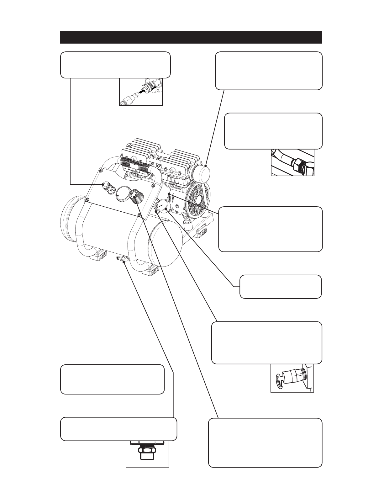
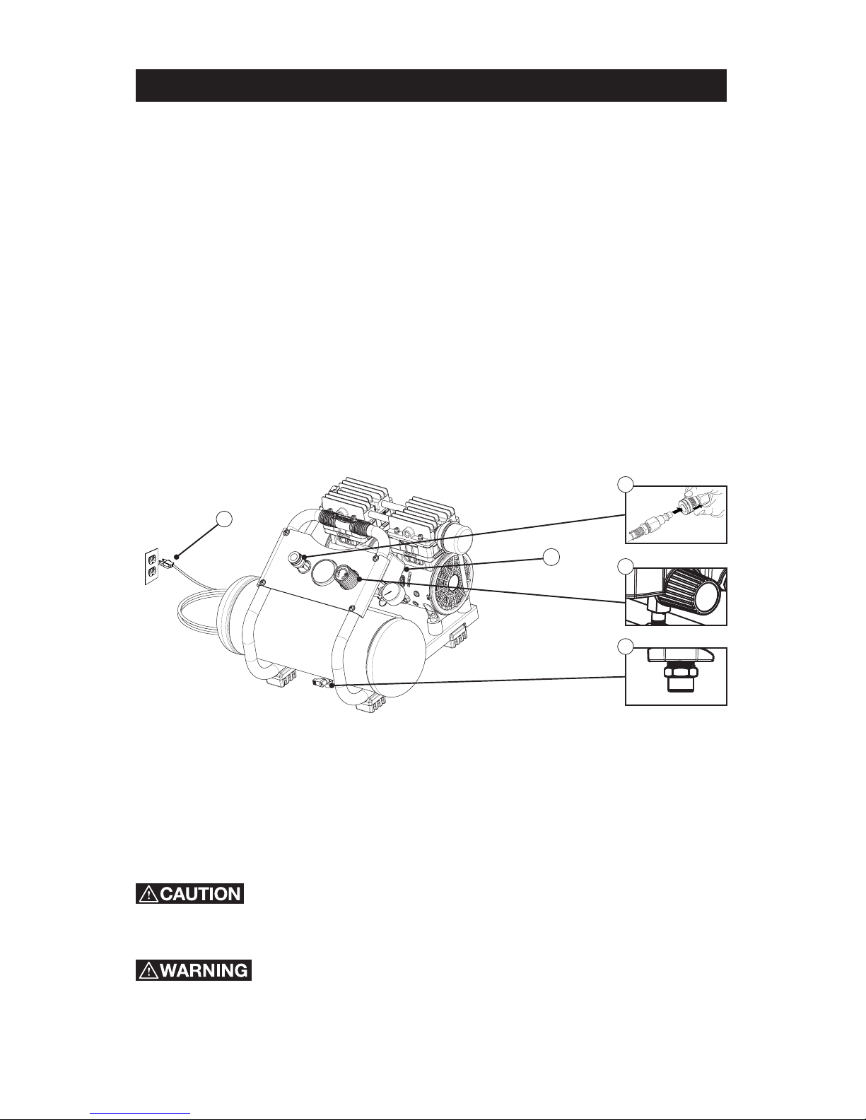
OVERVIEW
Figure 1
Regulator
The air pressure coming from the air
tank is controlled by the regulator.
To increase the pressure, turn the
knob clockwise,and to decrease
the pressure, turn the knob
counter-clockwise.
Tank Pressure Gauge
Indicates the reserve air
pressure in the tank.
Air Intake Filter
Provides clean air to the pump and
must always be kept free of debris.
Check on a daily basis or before
each use.
Auto/Off Switch
This controls the power to the
motor and also the cut-in/
cut-out pressure settings.
This switch serves as the
Auto-On/Off positions for the unit.
Tank Safety Valve
Used to allow excess tank
pressure to escape into the
atmosphere. This valve should only
open when the tank pressure is
above the maximum rated pressure.
Tool Pressure Gauge
Indicates the outgoing air pressure
to the tool and is controlled by
the regulator.
Quick Connect
Offers a quick release feature for
attaching and removing the air hose.
Tank Drain Valve
Used to drain condensation from the air
tank. Located at bottom of tank.
Check Valve (Not Visible)
When the pump is not in operation
the valve closes to retain air
pressure inside the tank. An
internal component.
Page 12
12- ENG
ASSEMBLING THE COMPRESSOR
The air compressor should be turned off, unplugged from the power source, the
air bled from the tank and the unit allowed time to cool before any maintenance
is performed. Personal injuries could occur from moving parts, electrical
sources, compressed air or hot surfaces. The quick connect assembly must
be attached before use. Failure to assemble correctly could result in leaks and
possible injury. If unsure of assembly instructions or you experience difficulty in
the assembly please call your local service department for further information.
1. Unpack the air compressor. Inspect the unit for damage. If the unit has been
damaged in transit, contact the carrier and complete a damage claim. Do
this immediately because there are time limitations to damage claims.
2. Check the compressor’s serial label to ensure that you have received the
model ordered, and that it has the required pressure rating for its
intended use.
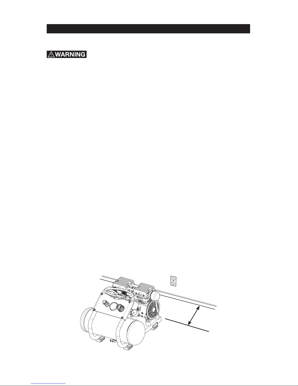
3. Locate the compressor according to the following guidelines:
a. Position the compressor near a grounded electrical outlet.
b. The compressor must be at least 12 inches (31 cm) from any wall or
obstruction, in a clean, well-ventilated area, to ensure sufficient air flow
and cooling.
c. In cold climates, store portable compressors in a heated building when
not in use. This will reduce problems with motor starting and freezing of
water condensation.
d. Remove the compressor from the carton and place it on the floor or a
hard, level surface. The compressor must be level to ensure proper
drainage of the moisture in the tank.
ASSEMBLY
12 inches
(31 cm)
Figure 2
Page 13
13 - ENG
GETTING STARTED
Location of the Air Compressor
The air compressor should always be located in a clean, dry and well ventilated
environment. The unit should have at minimum, 12 inches of space on each
side. The air filter intake should be free of any debris or obstructions. Check
the air filter on a daily basis to make sure it is clean and in working order.
This product incorporates snap action switch contacts and a induction electric
motor which tends to produce arcs and sparking and therefore should not
be exposed to flammable liquids or vapors. This product is not intended for
installation or use in a commercial garage or shop environment.
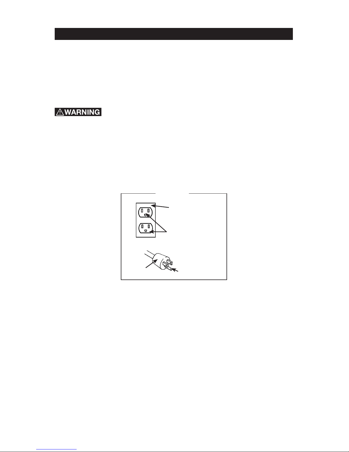
Grounding Instructions
This product must be grounded. In the event of an electrical short circuit,
grounding reduces the risk of electric shock by providing an escape wire for
the electric current. This product is equipped with a cord having a grounding
wire with an appropriate grounding plug. (See Figure 3.) The plug must be
plugged into an outlet that is properly installed and grounded in accordance
with all local codes and ordinances. Check with a qualified electrician or
service personnel if these instructions are not completely understood or if in
doubt as to whether the tool is properly grounded.
Improper installation of the grounding plug will result in a risk of electric shock.
If repair or replacement of the cord or plug is necessary, do not connect the
grounding wire to either flat blade terminal. The wire with insulation having an
outer surface that is green with or without yellow stripes is the grounding wire.
Substitution of the signal word “DANGER” for “WARNING” is not prohibited
when the risk associated with the product is such that a situation exists which
if not avoided will result in death or serious injury. Check with a qualified
electrician or serviceman if the grounding instructions are not completely
understood, or if in doubt as to whether the product is properly grounded. Do
not modify the plug provided; if it will not fit the outlet, have the proper outlet
installed by a qualified electrician.
This product is for use on a nominal 120-V circuit and has a grounding plug
similar to the plug illustrated in (Figure 3). Only connect the product to an outlet
having the same configuration as the plug. Do not use an adapter with this
product.
INSTALLATION
RISK OF ELECTRICAL SHOCK.
RISK OF EXPLOSION OR FIRE.
Page 14
14- ENG
GETTING STARTED
Extension Cords
Avoid use of extension cords. If use of an extension cord cannot be avoided, the
cord should be a minimum wire size of 14 AWG and no longer than 100 ft.
Use only a 3-blade grounding plug, and a 3-slot receptacle that will accept the
plug on the product.
Check extension cords before each use. If damaged, replace immediately.
Never use this product with a damaged cord. Touching the damaged area could
cause electrical shock resulting in serious injury.
Break In Procedures
No break in procedure is required by the user. This product is factory tested to
ensure proper operation and performance.
Figure 3
Grounded Outlet
Box
Grounded Outlet
Plug
Grounding Pin
120 VOLTS
INSTALLATION
Page 15
15 - ENG
DAILY STARTUP (Figure 4)
1. Set the Auto/Off switch to the Off position. (A)
2. Inspect the air compressor, air hose, and any accessories/tools being used
for damage or obstruction. If any of these mentioned items are in need
of repair/replacement, contact your local authorized dealer before use.
3. Close the drain valve. (B)
4. Connect the air hose to the quick connect socket on the regulator assembly
by inserting the quick connect plug on the air hose into the quick connect
socket. The quick connect socket collar will snap forward and lock the
plug into place providing an air tight seal between the socket and plug. To
release the air hose push the collar back on the quick connect socket. (C)
5. Plug the power cord into the proper receptacle. (D)
6. Set the Auto/Off switch to the Auto position and the compressor will start
and build air pressure in the tank to cut-out pressure and then shut
off automatically. (A)
7. Adjust the regulator to a PSI setting that is needed for your application and
be sure it is within the safety standards required to perform the task. If using
a pneumatic tool, the manufacturer should have recommendations in
the manual for that particular tool on operating PSI settings. (E)
SHUTDOWN (Figure 4)
1. Set the Auto/Off switch to the Off position. (A)
2. Unplug the power cord from the receptacle. (D)
3. Set the outlet pressure to zero on the regulator. (E)
4. Remove any air tools or accessories.
5. Open the drain valve allowing air to bleed from the tank.
After all of the air has bled from the tank, close the drain
valve to prevent debris buildup in the valve. (B)
When draining the tank, always use ear and eye protection. Drain the tank in a
suitable location; condensation will be present in most cases of draining.
Water that remains in the tank during storage will corrode and weaken the air
tank which could cause the tank to rupture. To avoid serious injury, be sure to
drain the tank after each use or daily.
OPERATING PROCEDURES
Figure 4
E
C
B
D
A
Page 16
16- ENG
MAINTENANCE
Figure 5
To avoid personal injury, always shut off and unplug the compressor and relieve all
air pressure from the system before performing any service on the air compressor.
To ensure efficient operation and longer
life of the air compressor unit, a routine
maintenance schedule should be followed.
The following schedule is geared toward
a consumer whose compressor is used in
a normal working environment on a daily
basis.
This compressor is equipped with a thermal overload protector which will shut
off motor if it becomes overheated. If the thermal overload protector is actuated,
the motor must be allowed to cool down before start-up is possible. To reset the
motor overload, turn the Power Switch to the OFF position and unplug the unit
from the power outlet. Allow 10 minutes (minimum) for motor overload cut-out to
cool and reset. Unit can then be plugged in and re-started.
Maintenance Schedule
Items to Check/Change
Before each use
or daily
Check Tank Safety Valve X
Overall Unit Visual Check X
Drain Tank X
Check Power Cord for
Damage
X
DRAINING THE TANK
Condensation will accumulate in the tank. To prevent corrosion of the tank from
the inside, this moisture must be drained at the end of every workday. Be sure
to wear protective eyewear. Relieve the air pressure in the system and open the
drain valve on the bottom of the tank and tilt tank to drain.
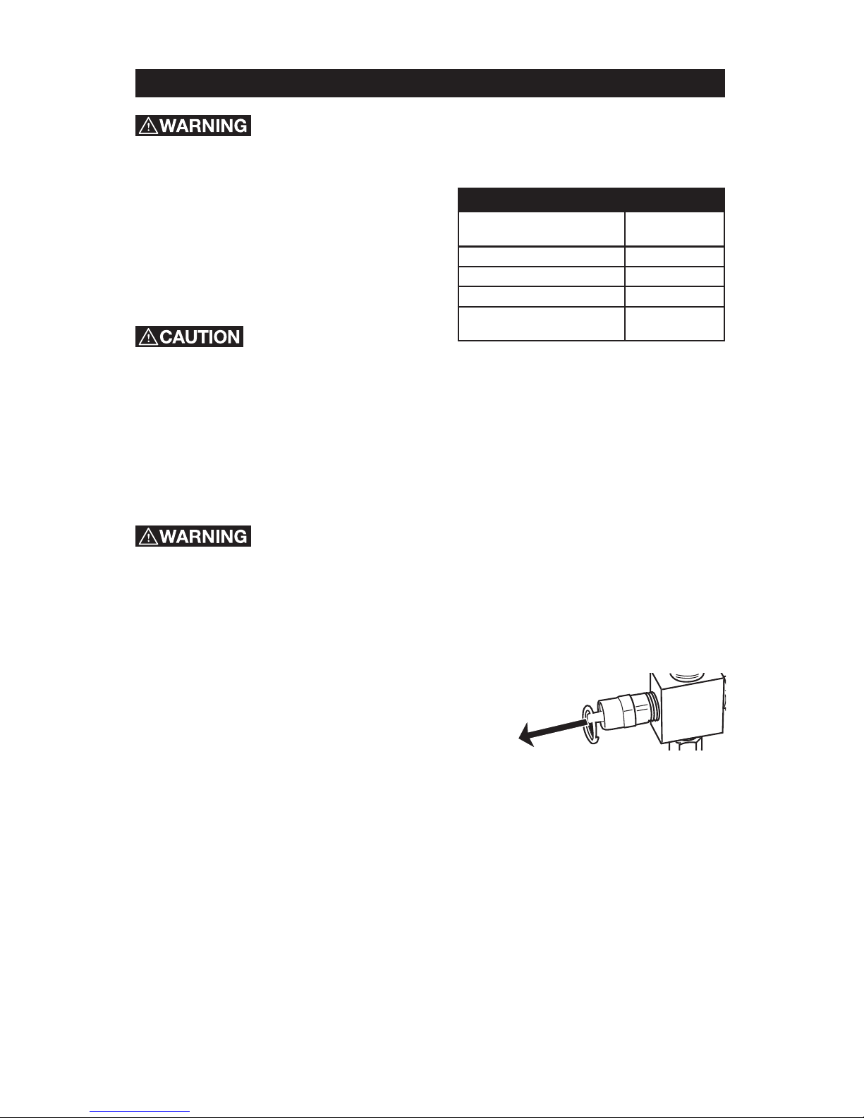
CHECKING THE SAFETY VALVE (Figure 5)
Check the safety valve by performing these three steps:
1. Plug the compressor in and run until cut-off
pressure is reached.
2. Wearing safety glasses, pull out on the safety
valve ring to release pressure from the tank.
3. The safety valve should close automatically at approximately 40-50 PSI.
If the safety valve does not allow air to be released when you pull
out on the ring, or does not close automatically, it must be replaced.
STORAGE
For storing the air compressor, be sure to do the following:
1. Turn the unit off and unplug the power cord from the receptacle.
2. Remove all air hoses, accessories, and air tools from the air compressor.
3. Perform the daily maintenance schedule.
4. Open the drain valve to bleed all air from the tank.
5. Close the drain valve.
6. Protect the electrical cord and air hose from damage (such as being stepped
on or run over). Wind them loosely around the compressor handle.
7. Store the air compressor in a clean and dry location.
Page 17
17 - ENG
TROUBLESHOOTING
Risk of Unsafe Operation. Unit cycles automatically when power is on. When
servicing, you may be exposed to voltage sources, compressed air, or moving
parts. Before servicing unit unplug or disconnect electrical supply to the air
compressor, bleed tank of pressure, and allow the air compressor to cool.
PROBLEM CAUSE CORRECTION
Low pressure or
not enough air
or Compressor
does not stop
Tank drain valve is open Close drain valve.
Fittings leak Check fittings with soapy water.
Tighten or reseal leaking fittings.
DO NOT OVERTIGHTEN.
Restricted air intake Clean or replace intake filter element.
Prolonged excessive
use of air
Decrease amount of air used.
Compressor not
large enough
Check air requirement of accessory.
If it is higher than CFM and
pressure supplied by compressor,
you need a larger compressor.
Most accessories are rated at 25% of
actual CFM while running continuously.
Hole in air hose Check and replace if necessary.
Tank leaks
Immediately replace
tank. DO NOT attempt to repair.
Blown seals Replace seals.
Valve leaks Replace valves.
Leaking or worn piston Replace piston.
Air leaks from
regulator, or
regulator does
not regulate
pressure
Dirty or damaged
regulator internal parts
Replace regulator or internal parts.
Page 18

18- ENG
PROBLEM CAUSE CORRECTION
Regulated
pressure
gauge reading
drops when
air accessory
is being used
This is normal If pressure drops too low, adjust
regulator while accessory is used.
Compressor not
large enough
Check air requirement of accessory.
If it is higher than CFM and pressure
supplied by compressor, you need a
larger compressor. Most accessories
are rated at 25% of actual CFM
while running continuously.
Pressure relief
valve opens
Tank pressure
exceeded normal
operating pressure
Replace pressure switch.
Pressure switch stuck Replace pressure switch.
Motor will
not run
Tank pressure exceeds
preset pressure switch
limit
Motor will start automatically when
tank pressure drops below cut- in
pressure of pressure tank.
Make sure the Thermal
Overload Switch has not
tripped. The motor has
a built in thermal cut out
that trips when necessary
to protect the motor
from damage when
overheated.
Fuse blown or circuit
breaker tripped
To reset the motor overload, turn the
Power Switch to the OFF position and
unplug the unit from the power outlet.
Allow 10 minutes (minimum) for motor
overload cut-out to cool and reset. Unit
can then be plugged in and re-started.
• Replace blown fuse or reset
circuit breaker. Do not use fuse or
circuit breaker with higher rating
than specified for your branch circuit.
• Check for proper fuse; “Fusetron”
type T is acceptable.
• Check for low voltage and
proper extension cord size.
• Disconnect other applications
from circuit. Operate compressor
on a dedicated circuit.
Check valve stuck open Remove and clean or replace.
Wrong wire gauge in cord
or excessive extension
cord length
Check for proper gauge and extension
cord length.
Loose electrical
connections
Contact authorized service center.
Paint spray on internal
motor parts
Have checked at service center. Do
not operate compressor in the paint
spray area.
Possible defective motor Have checked at service center.
Page 19
19 - ENG
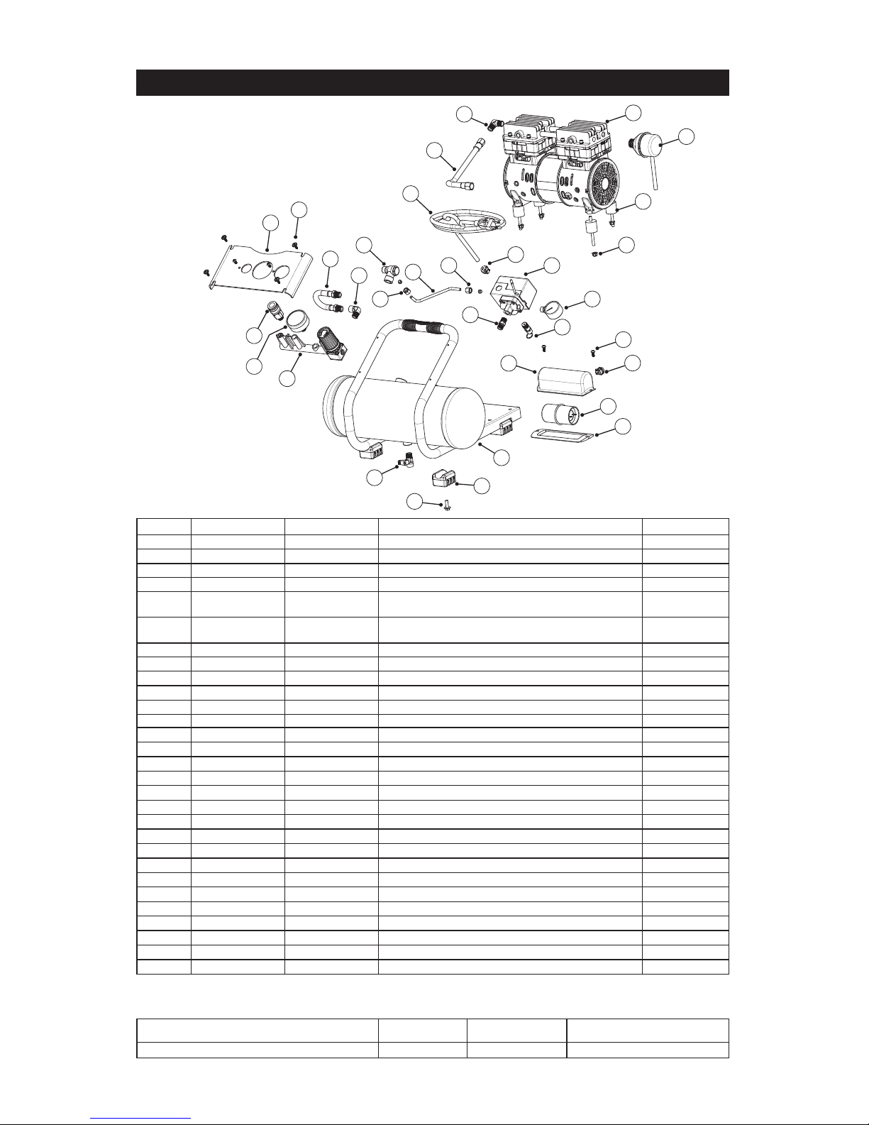
SAC22HPP
ITEM. NO KIT # PART NO. DESCRIPTION QTY
1
E110726 Pump / Motor Assembly Q2.0
1
2
E106954 Air Filter Assy
1
3
E110782 Cushion Pad
4
4
Nut Hex Flange M6 x 1 Nylon Insert
4
5 E111127
Pressure Switch 125 PSI 3 x 1/4 NPT x 1/8 NPT
Base
1
6 E111122
Gauge 38 mm, 125 PSI Red Line, 9-O'Clock side
feed 1/8 NPT
1
7
E102595 Safety Valve
1
8
Nipple 1/4 NPT
1
9
M4 Self Tapping Screw
2
10 E100594
Strain Relief 14/3 SJT
2
11 E110785
Capacitor Cover
1
12 E110786
Capacitor 90uF
1
13
Rubber Gasket
1
14
Frame/Tank Weldment 2 Gallon
1
15 E109475
Isolator Foot
4
16
Screw 1/4 - 20 x .75
4
17 E107047
Drain Valve 1/4 Turn
1
18 E101951
Assy, Manifold / Regulator
1
19 E102822
Quick Connect
1
20 E103746
Gauge, Pressure 50 mm 0-250 PSI w/ 125 Red Line
1
21 E101968
Hose Manifold, 3/8" ID Rubber
1
22
Elbow Male x Female 1/4NPT
1
23
Panel Manifold
4
24
Screw #8 4 mm x 20 mm Washer Head
1
25 E100898
Check Valve
1
26 1
Ferrule 1/4
2
27
1
Pressure Relief Tube 1
28 1
Nut 1/4
2
29
E110787 Power Cord, 14GA SJT 3 Wire w/Cleat
1
PARTS DRAWING
KIT NAME KIT # ORDER # COMPONENT REFERENCE #
Pressure Relief Tube Kit 1 E102025 26,27,28
Note: Any part number field without a number listed is not available. Descriptions are provided for
reference only. Kit numbers, descriptions, and included components are listed below:
1
2
3
4
13
14
15
16
28
29
30
31
27
25
22
18
19
21
24
23
12
8
10
10
11
9
6
5
7
26
20
17
Page 20
20- SP
10/04/2017
Número de parte: E110923
Manual del propietario
Compresor de aire
7.57 litros
1.0 HP
Sin aceite
Modelo Noº SAC22HPP
PRECAUCIÓN: Before Antes de utilizar este producto, lea este manual y siga las reglas de
seguridad e instrucciones de operación incluidas.
• Instrucciones de seguridad
• Instalación y modo de empleo
• Mantenimiento y almacenamiento
• Diagnóstico y corrección de fallas
• Lista de las piezas
ADVERTENCIA DE LA PROPUESTA DE LEY 65 DE CALIFORNIA: Este producto
contiene substancias químicas que, consta al Estado de California, producen cáncer,
malformaciones congénitas o daños reproductivos.
MAT Industries, LLC
Jackson, TN 38301 U.S.A.
www.powermate.com
Page 21

21 - SP
Garantía ..........................................................................21
Símbolos de seguridad ..............................................................22
Instrucciones y pautas importantes de seguridad .........................................22
Peligro ........................................................................22-28
Especificaciones ...................................................................28
Glosario ..........................................................................29
Ciclo de servicio ...................................................................30
Descripción general .................................................................31
Ensamblaje .......................................................................32
Instalación ..................................................................... 33-34
Procedimientos de operación .........................................................35
Mantenimiento ..................................................................36-37
Almacenamiento ...................................................................37
Guía de diagnóstico de problemas .................................................. 38-39
Lista de las piezas ............................................................... 40-41
Número de servicio ...................................................... cubierta trasera
¿Qué cubre esta garantía? MAT Industries, LLC. (la Compañía) garantiza a partir de la fecha de compra al menudeo del comprador original
solamente, piezas y mano de obra para corregir defectos importantes en los materiales y la fabricación.
¿Cuánto dura la cobertura? Esta garantía tiene una duración de un año y no se puede transferir a propietarios futuros.
Qué hará Sanborn Mfg.: Sanborn Mfg se cubren las piezas y mano de obra para remediar los defectos sustanciales debido a los materiales y mano
de obra durante el primer año de propiedad, con las excepciones que se indican a continuación, y sólo algunas partes, para remediar los defectos
sustanciales debido a materiales y mano de obra durante el plazo restante de la cobertura con la excepciones que se indican a continuación. Las
piezas utilizadas en la reparación de los bienes total o accesorios son garantizados por el resto del período de garantía original.
¿Qué no cubre esta garantía? Si el comprador al menudeo original no instala, mantiene y opera dicho equipo de acuerdo con las prácticas
industriales estándar. Las modificaciones al producto o alteraciones a los componentes, o el incumplimiento con las recomendaciones específicas
de la Compañía que se establecen en el manual del propietario, anularán esta garantía. La Compañía no será responsable de reparaciones,
reemplazos o ajustes al equipo, ni de costos de mano de obra realizada por el comprador sin la aprobación previa por escrito de la Compañía. Los
efectos de la corrosión, erosión, condiciones ambientales circundantes, defectos cosméticos y elementos de mantenimiento de rutina, se excluyen
específicamente de esta garantía. Los elementos de mantenimiento de rutina, como aceite, lubricantes y filtros de aire, así como los cambios
de aceite, filtros de aire, tensión de bandas, etc., son responsabilidad del propietario. Otras exclusiones incluyen: daños durante el flete, fallas
originadas por negligencia, accidente o abuso, motores de inducción cuando es operado desde un generador, filtraciones de aceite, fugas de aire,
consumo de aceite, acoples con fugas, mangueras, grifos, tubos de purga y tubos de transferencia.
Si el compresor se utiliza en aplicaciones comerciales, industriales, o militares, la garantía se aplicará por un periodo de 90 días a partir de la fecha
de compra. Los compresores de dos etapas no están limitados a una garantía de 90 días si se utilizan en aplicaciones comerciales o industriales.
• Las aplicaciones de alquiler causan la anulación e invalidación de esta garantía.
• Los siguientes componentes se consideran artículos de desgaste por el uso normal y no están cubiertos después del primer año de
posesión: Correas, roldanas, volantes, válvulas de retención, interruptores de presión, descargadores neumáticos, controles
de aceleración, motores eléctricos, escobillas, reguladores, anillos en O, manómetros, tubos, tuberías, acoplamientos, sujetadores,
ruedas, acopladores rápidos, empaquetaduras, sellos, carcasas de filtro de aire, anillos de pistón, varillas de conexión y sellos de pistón.
• Los costos de mano de obra, llamadas de servicio y viajes, no están cubiertos después del primer año de propiedad de los compresores
estacionarios (compresores sin asas o ruedas). No están cubiertas las reparaciones que requieren horas extraordinarias, tarifas de fin de
semana o cualquier otro costo que supere las tarifas por mano de obra estándar del taller.
• Tiempo requerido para la capacitación de orientación con el fin de que el centro de servicio obtenga acceso al producto, o tiempo
adicional debido a un egreso inadecuado.
• El daño causado por voltaje incorrecto, cableado inapropiado o el hecho de no hacer que un electricista certificado con licencia instale el
compresor, causará la anulación e invalidación de esta garantía.
• Daño causado por un mantenimiento inadecuado del filtro.
• Desgaste de la bomba o daño en la válvula causado por el uso de aceite no especificado.
• Desgaste de la bomba o daño causado por cualquier contaminación del aceite.
• Desgaste de la bomba o daño en la válvula causado por el hecho de no seguir las directrices de mantenimiento apropiadas.
• Utilización con un nivel de aceite por debajo del apropiado o utilización sin aceite.
• Para motores a gas, si el producto está equipado con un motor a gas, consulte en el manual la cobertura de garantía del fabricante para
el motor específico.
Piezas que se compran por separado: las garantías de las piezas que se compran por separado, como bombas, motores, etc., son las
siguientes:
A partir de la fecha de compra
• Todas las bombas de una y dos etapas 1 año
• Motores eléctricos 90 días
• Bomba/motor universal 30 días
• Todas las otras piezas 30 días
• No se expedirá una autorización de devolución para los componentes eléctricos una vez que estén instalados.
¿Cómo puede obtener servicio? Con el fin de ser elegible para obtener servicio bajo esta garantía, debe ser el comprador al menudeo original
y proporcionar un comprobante de compra de uno de los concesionarios, distribuidores o tiendas minoristas de Sanborn. Los compresores
portátiles o los componentes se deben enviar o entregar en el Centro de Servicio autorizado de Sanborn más cercano. El cliente deberá pagar
todos los costos relacionados con el flete y viaje. Para obtener asistencia, llame a nuestro número gratuito, 1-888-895-4549.
ESTA GARANTÍA LE OTORGA DERECHOS LEGALES ESPECÍFICOS, Y ES POSIBLE QUE TAMBIÉN TENGA OTROS DERECHOS QUE
VARÍAN DE UN ESTADO A OTRO. LA COMPAÑÍA NO HACE REPRESENTACIÓN O GARANTÍA ALGUNA, YA SEA EXPRESA O IMPLÍCITA,
A EXCEPCIÓN DE LA DEL TÍTULO DE PROPIEDAD. POR LA PRESENTE, LA COMPAÑÍA NO ASUME NINGUNA GARANTÍA IMPLÍCITA,
INCLUIDAS LAS GARANTÍAS DE COMERCIABILIDAD Y DE IDONEIDAD PARA UN PROPÓSITO ESPECÍFICO. SE EXCLUYE TODA
RESPONSABILIDAD POR DAÑOS Y PERJUICIOS EMERGENTES O INCIDENTALES EN VIRTUD DE CUALQUIER OTRA GARANTÍA, OTROS
CONTRATOS, NEGLIGENCIA U OTROS ACTOS DE AGRAVIO EN LA MEDIDA EN QUE LA LEY LO PERMITA.
MAT Industries, LLC, Jackson, TN 38301 U.S.A.
GRANTÍA LIMITADA DE 1 AÑO
ÍNDICE DE MATERIAS
Page 22

22- SP
INSTRUCCIONES IMPORTANTES DE SEGURIDAD
Este manual contiene información que es importante que usted conozca y
comprenda. Esta información se relaciona con la protección de SU SEGURIDAD
y LA PREVENCIÓN DE PROBLEMAS A SU EQUIPO. Para ayudarle a reconocer
esta información, usamos los símbolos indicados más abajo. Sírvase leer el
manual y prestar atención a estas secciones.
PARA REDUCIR EL RIESGO DE LESIONES, LEA
EL MANUAL DE INSTRUCCIONES.
¿QUÉ PUEDE SUCEDER? CÓMO EVITARLO
• Es normal que los contactos
eléctricos dentro del motor
y el interruptor de presión
produzcan chispas.
• Opere siempre el compresor en
un área bien ventilada libre de
materiales combustibles, gasolina
o vapores de solventes.
• Si las chispas eléctricas del
compresor entran en contacto
con vapores inflamables, pueden
encenderse, provocando un
incendio o una explosión.
• Si se pulverizan materiales
inflamables, ubique el compresor
al menos a 6,1 m (20 pies) del
área de pulverización. Se puede
necesitar manguera adicional.
• Guarde los materiales inflamables en
lugar seguro lejos del compresor.
Conserve estas instrucciones
Indica una situación de riesgo inminente, que si no se
evita, causará la muerte o lesiones serias.
Indica una situación potencialmente riesgosa, que si no
se evita, podría causar la muerte o lesiones serias.
Indicates a potentially hazardous situation which, if not
avoided, may result in minor or moderate injury.
Se refiere a una práctica no relacionada a lesiones
corporales que de no evitarse puede resultar en daños a
la propiedad.
AVISO
RIESGO DE EXPLOSIÓN O INCENDIO.
PELIGRO
SÍMBOLOS DE SEGURIDAD
Page 23

23 - SP
• Restringir cualquiera de las
aberturas de ventilación del
compresor puede producir un
sobrecalentamiento grave y
podría provocar un incendio.
• Nunca coloque objetos contra
o sobre el compresor.
• Opere el compresor en un lugar
abierto con una distancia de al
menos 30,5 cm (12 pulg.) a cualquier
pared u obstrucción que pudiera
restringir el flujo de aire fresco a
las aberturas de ventilación.
• Opere el compresor en un área
limpia, seca y bien ventilada. No
opere la unidad dentro en un área
muy cerrada. Almacén en puertas.
• El funcionamiento sin cuidado de
este producto podría provocar
lesiones personales o daños a
la propiedad. Para disminuir el
riesgo de incendio, no permita
que el compresor funcione
sin que alguien lo controle.
• Siempre permanezca
controlando el producto cuando
está en funcionamiento.
• Siempre apague y desenchufe la
unidad cuando no esté en uso.
¿QUÉ PUEDE SUCEDER? CÓMO EVITARLO
• El aire comprimido que sale de
su compresor no es seguro para
respirarlo. El flujo de aire puede
contener monóxido de carbono,
vapores tóxicos o partículas sólidas
del tanque de aire. De respirar estos
contaminantes puede provocar
lesiones graves o la muerte.
• El aire que se obtiene directamente
del compresor no se debe usar
nunca para consumo humano.
El compresor no incluye equipo
de seguridad en línea y filtros
adecuados para consumo humano.
• La exposición a los productos
químicos en el polvo producido
por las herramientas eléctricas
al lijar, aserrar, esmerilar, taladrar
y otras actividades de la
construcción puede ser peligrosa.
• Los materiales pulverizados como
pinturas, solventes para pinturas,
removedores de pintura, insecticidas
y herbicidas pueden contener
vapores dañinos y venenos.
• Trabaje en un área con buena
ventilación cruzada. Lea y siga
las instrucciones de seguridad
que se proveen en la etiqueta
o en la ficha técnica de los
materiales que está utilizando.
Siempre utilice equipamiento de
seguridad certificado: protección
respiratoria aprobada por NIOSH/
OSHA o una mascarilla facial
adecuada diseñada para usar para
los fines que usted requiere.
RIESGO RESPIRATORIO (ASFIXIA).
PELIGRO
Page 24

24- SP
PELIGRO
RIESGO DE EXPLOSIÓN.
¿QUÉ PUEDE SUCEDER? CÓMO EVITARLO
• No drenar correctamente el agua
condensada del tanque de aire, que
provoca óxido y adelgazamiento
del tanque de aire de acero.
• Drene el tanque diariamente o
luego de cada uso. Si un tanque
de aire presenta una pérdida,
reemplácelo inmediatamente
con un tanque nuevo o
reemplace todo el compresor.
• Modificaciones o intento de
reparación del tanque de aire.
• Nunca perfore, suelde o haga
ninguna modificación al tanque
de aire o a sus elementos.
Nunca intente reparar un
tanque de aire dañado o con
pérdidas. Reemplácelo con
un tanque de aire nuevo.
• Las modificaciones no autorizadas
de la válvula de seguridad o
cualquier otro componente que
controle la presión del tanque.
• El tanque está diseñado para
soportar determinadas presiones
de operación. Nunca realice
ajustes ni sustituya piezas
para cambiar las presiones de
operación fijadas en la fábrica.
Elementos y accesorios:
• Exceder las indicaciones de
presión para las herramientas
neumáticas, las pistolas
pulverizadoras, los accesorios
neumáticos, los neumáticos y
otros artículos inflables puede
hacer que exploten o revienten, y
puede provocar lesiones graves.
• Siga la recomendación del
fabricante del equipo y nunca
exceda el nivel máximo de presión
aceptable para los elementos.
Nunca utilice el compresor
para inflar objetos pequeños
de baja presión, tales como
juguetes de niños, pelotas de
fútbol o de basquetbol, etc.
AVISO: El 26 de febrero de 2002, la Comisión de Seguridad para Productos
de Consumo delos Estados Unidos publicó el Comunicado # 02-108 sobre la
seguridad en los tanques de compresores de aire:
• Los tanques receptores de los compresores de aire no tienen una vida útil
infinita. La vida útil del tanque depende de diversos factores, incluyendo las
condiciones de operación, las condiciones ambientales, la instalación debida
del mismo, modificaciones realizadas en el campo y el nivel de
mantenimiento que reciba. Es difícil prever cuál será el efecto exacto de
estos factores sobre la vida útil del tanque receptor de aire.
• Si no se siguen procedimientos de mantenimiento debidos, la corrosión
interna de la pared interior del tanque receptor de aire puede causar una
ruptura imprevista en el tanque de aire, lo que hará que el aire presurizado
escape con fuerza y repentinamente, pudiendo lesionar al usuario.
• El tanque de aire de su compresor debe ser descomisionado al final del año
mencionado en la etiqueta de advertencia que se fija al tanque.
• Las siguientes condiciones pueden llevar a debilitar el tanque de aire y
ocasionar la explosión violenta del mismo.
Page 25

25 - SP
PELIGRO
Neumáticos:
• El inflado excesivo de los
neumáticos podría causar lesiones
graves y daño a la propiedad.
• Utilice un medidor de presión
de neumáticos para controlar
la presión de éstos antes de
cada uso y mientras los infla;
observe el flanco para ver la
presión correcta del neumático.
NOTA: Los tanques de aire, los
compresores y el equipo similar que
se usa para inflar neumáticos pueden
llenar neumáticos pequeños como
éstos con mucha rapidez. Ajuste el
regulador de presión en el suministro
de aire a un valor que no supere el
de la presión del neumático. Agregue
aire en forma gradual y use con
frecuencia el medidor de presión de
neumáticos para evitar inflarlos.
RIESGO DE DESCARGA ELÉCTRICA.
¿QUÉ PUEDE SUCEDER? CÓMO EVITARLO
• Su compresor de aire funciona
con electricidad. Como cualquier
otro mecanismo que funciona
con electricidad, si no se lo
utiliza correctamente puede
provocar descargas eléctricas.
• Nunca haga funcionar el compresor
al aire libre cuando está lloviendo
o en condiciones de humedad.
• Nunca haga funcionar el
compresor sin las cubiertas de
protección o si están dañadas.
• Que personal no calificado
intente realizar reparaciones
puede provocar lesiones graves
o muerte por electrocución.
• Cualquier cableado eléctrico o las
reparaciones requeridas para este
producto deben ser realizadas por
un centro de servicio de un centro
de mantenimiento autorizado
de acuerdo con los códigos
eléctricos nacionales y locales.
• Puesta a tierra: La no colocación
de la puesta a tierra adecuada
para este producto puede
provocar lesiones graves o muerte
por electrocución. Consulte
las Instrucciones de Conexión
a tierra en Instalación.
• Asegúrese de que el circuito
eléctrico al que se conecta el
compresor suministre la conexión a
tierra adecuada, el voltaje adecuado
y el fusible de protección adecuado.
Page 26

26- SP
PELIGRO
¿QUÉ PUEDE SUCEDER? CÓMO EVITARLO
• La corriente de aire comprimido
puede provocar lesiones en los tejidos
blandos de la piel expuesta y puede
impulsar suciedad, astillas, partículas
sueltas y objetos pequeños a gran
velocidad, que pueden producir daños
en la propiedad y lesiones personales.
• Utilice siempre equipo de
seguridad certificado: anteojos
de seguridad ANSI Z87.1 (CAN/
CSA Z94.3) con protección
lateral al usar el compresor.
• Nunca apunte ninguna
boquilla ni pulverizador a ninguna parte del cuerpo o a
otras personas o animales.
• Apague siempre el compresor y
drene la presión de la manguera
de aire y del tanque de aire antes
de intentar hacer mantenimiento,
conectar herramientas o accesorios.
RIESGO DE OBJETOS DESPEDIDOS.
RIESGO DE SUPERFICIES CALIENTES.
¿QUÉ PUEDE SUCEDER? CÓMO EVITARLO
• Tocar metal expuesto como el
cabezal del compresor, el cabezal
del motor, el escape del motor,
o los tubos de salida puede
provocar quemaduras graves.
• Nunca toque ninguna parte
metálica expuesta del compresor
durante o inmediatamente
después de su funcionamiento.
El compresor continuará caliente
durante varios minutos después
de su funcionamiento.
• No toque las cubiertas
protectoras ni intente realizar
mantenimiento hasta que la
unidad se haya enfriado.
Page 27

27 - SP
RIESGO POR PIEZAS MÓVILES.
RIESGO DE OPERACIÓN INSEGURA.
PELIGRO
¿QUÉ PUEDE SUCEDER? CÓMO EVITARLO
• Las piezas móviles como la polea, el
volante y la correa pueden provocar
lesiones graves si entran en
contacto con usted o con sus ropas.
• Nunca haga funcionar el compresor
sin los protectores o cubiertas o
si los mismos están dañados.
• Mantenga el cabello, la ropa
y los guantes alejados de las
piezas en movimiento. Las
ropas holgadas, las joyas o el
cabello largo pueden quedar
atrapados en las piezas móviles.
• Los orificios de ventilación pueden
cubrir piezas en movimiento, por
lo que también se deben evitar.
• Intentar hacer funcionar el
compresor con partes dañadas
o faltantes, o intentar reparar
el compresor sin las cubiertas
protectoras puede exponerlo
a piezas móviles lo que puede
provocar lesiones graves.
• Cualquier reparación requerida por
este producto debe ser realizada
por un centro de servicio de un
centro de servicio autorizado.
¿QUÉ PUEDE SUCEDER? CÓMO EVITARLO
• La operación insegura de su
compresor de aire podría producir
lesiones graves o la muerte, a
usted mismo o a otras personas.
• Revise y comprenda todas las
instrucciones y advertencias
de este manual.
• Familiarícese con la operación y los
controles del compresor de aire.
• Mantenga el área de
operaciones libre de personas,
mascotas y obstáculos.
• Mantenga a los niños
alejados del compresor de
aire en todo momento.
• No opere el producto cuando
esté cansado o bajo la influencia
de alcohol o drogas. Manténgase
alerta en todo momento.
• Nunca anule las características
de seguridad de este producto.
• Equipe el área de operaciones
con un extintor de incendios.
• No opere la máquina si faltan
piezas, si éstas están rotas o
si no son las autorizadas.
Page 28

28- SP
PELIGRO
RIESGO DE CAÍDAS.
¿QUÉ PUEDE SUCEDER? CÓMO EVITARLO
• Un compresor portátil se puede
caer de una mesa, banco o techo,
provocando daños al compresor
y puede producir lesiones graves
o la muerte del operador.
• Opere siempre el compresor en
una posición estable y segura para
evitar que la unidad se mueva
accidentalmente. Nunca opere el
compresor sobre un techo u otra
ubicación elevada. Utilice una
manguera de aire adicional para
alcanzar las ubicaciones elevadas.
RIESGO DE LESIÓN POR LEVANTAR
MUCHO PESO
¿QUÉ PUEDE SUCEDER? CÓMO EVITARLO
• El intento de levantar un
objeto muy pesado puede
provocar lesiones graves.
• El compresor es demasiado
pesado como para que lo levante
una sola persona. Consiga ayuda
de otras personas para levantarlo.
RIESGO POR RUIDOS.
¿QUÉ PUEDE SUCEDER? CÓMO EVITARLO
• En determinadas condiciones y
según el período de uso, el ruido
provocado por este producto puede
originar pérdida de audición.
• Utilice siempre equipo de
seguridad certificado: protección
auditiva ANSI S12.6 (S3.19).
Modelo Nº SAC22HPP
Potencia de trabajo 1,0 *
Voltaje 120
manofásica- corriente 60
Circuito mínimo requerido 15A
Tipo de fusible Acción retardada
Capacidad de aire en el tanque 7,57 litros (2 Galones)
Presión de aire máxima 125 PSI
Presión de corte de entrada 95 PSIG
Presión de corte de salida 125 PSIG
SCFM a 40 psig 3,0 * Calibre de libras por pulgada cuadrada
SCFM a 90 psig 2,0 * Calibre de libras por pulgada cuadrada
*Probado según la norma ISO 1217
Refiérase al glosario para descifrar las abreviaturas.
CUADRO DE ESPECIFICACIONES
Page 29

29 - SP
GLOSARIO
Bomba
Es el dispositivo que produce el aire
comprimido mediante un pistón de
vaivén contenido dentro del cilindro.
Filtro de aire
Es un elemento poroso contenido dentro
de un alojamiento de metal o plástico
unido al cilindro de la culata del cilindro
del compresor, el cual sirve para eliminar
las impurezas del aire de entrada del
compresor.
Interruptor de presión
Sirve para controlar los ciclos de
encendido y apagado del compresor.
Apaga el compresor cuando se alcanza
la presión de interrupción del tanque y
arranca el compresor cuando la presión
del aire desciende abajo de la presión de
interrupción.
Interruptor de sobrecarga térmica
Sirve para apagar automáticamente
el compresor si la temperatura del
motor eléctrico se excede de un límite
predeterminado.
Manómetro del tanque
Sirve para indicar la presión interna
del tanque.
Manómetro regulador
Muestra la presión actual en el
conducto. La presión del conducto se
ajusta girando la perilla de regulación
de presión.
Motor eléctrico
Es el dispositivo encargado de
suministrar la fuerza rotatoria necesaria
para accionar la bomba del compresor.
NPT (Norma Nacional de Roscado de
Tubos)
Debe utilizarse una cinta selladora de
roscas para tener un sello a prueba de
fugas en las conexiones roscadas
de tubos.
PCEPM
(Pies cúbicos estándar por minuto)
La unidad de medida de suministro
de aire.
Perilla de regulación de presión
Sirve para regular la presión de la
salida de aire dirigida a la herramienta.
Es posible aumentar o disminuir la
presión presente en la salida ajustando
esta perilla de control. El interruptor
de presión no enciende y controla
automáticamente el compresor a menos
que el interruptor de Auto/Apagado
manual esté en la posición de AUTO.
Presión de activación
Es la presión baja a la cual arranca
automáticamente el motor.
Presión de interrupción
Es la presión alta a la cual se apaga
automáticamente el motor.
PSI (Libras por pulgada cuadrada)
Son las unidades de medida de la
presión ejercida por la fuerza del aire.
La presión real en PSI es medida por el
manómetro del compresor.
Tanque de aire
Es un componente cilíndrico que
contiene el aire comprimido.
Válvula de presión alivio
Su función es impedir que la presión
del aire ascienda más allá de un límite
predeterminado.
Válvula de retención
Es un dispositivo cuya función es
impedir que el aire comprimido se
regrese del tanque de aire a la bomba
del compresor.
Page 30

30- SP
Esta bomba compresora de aire es capaz de funcionar continuamente, sin embargo
para prolongar la vida útil de su compresor de aire se recomienda mantener un
ciclo promedio de servicio que oscile entre el 50% y el 75%; ello significa que la
bomba compresora no debería trabajar más de 30 a 45 minutos por hora.
Los accesorios pueden encontrarse en el comercio donde fue comprada la
unidad, o en un local de artículos de ferretería.
El uso de accesorios no recomendados para utilizar con esta herramienta puede
resultar peligroso. Use solamente accesorios con una capacidad nominal igual o
superior a la de la compresor de aire.
CICLO DE SERVICIO
ACCESORIOS
Page 31

31 - SP
DESCRIPCIÓN GENERAL
Conector de acoplamiento rápido
Permite conectar y desconectar
rápidamente la manguera de aire.
Válvula de retención (No visible)
Cuando la bomba no está en
operación, esta válvula se cierra
para mantener la presión de aire
dentro del tanque. Es un
componente interno.
Válvula de seguridad del tanque
Permite que el exceso de presión en
el tanque escape al medio ambiente.
Esta válvula sólo se abrirá cuando la
presión en el tanque esté por
encima de la presión máxima nominal
del modelo.
Regulator
La presión del aire que sale del tanque
es controlada por el regulador. Para
aumentar la presión, gire la perilla
ra disminuirla, gire la perilla en el
sentido contrario del reloj.
Manómetro para el tanque
Indica la presión que se encuentra
dentro del tanque.
Filtro de entrada de aire
Suministra aire limpio a la bomba y
siempre debe estar libre de
suciedad. Revíselo diariamente o
antes de cada uso.
Interruptor Auto/Off
Controla el suministro eléctrico al
motor y tambiénlos ajustes de
presión de arranque y presión de
parada. Este interruptor sirve como
posición de autoencendido y
apagado (Auto-On/Off) de la unidad.
Manómetro para herramientas
Indica la presión de salida del aire
que se reparte en la herramienta,
presión que es controlada por
el regulador
Válvula de drenaje
Utilizada para drenar la condensación
acumulada en el tanque. Se encuentra en
la parte inferior del tanque.
Page 32

32- SP
MONTAJE DEL COMPRESOR
Antes de darle cualquier tipo de mantenimiento, debe apagar y desenchufar el
compresor de aire de la fuente de alimentación eléctrica, además debe purgar el
aire del tanque y darle suficiente tiempo para enfriarse. Existe el riesgo de que
las partes móviles, las fuentes eléctricas, el aire comprimido y las superficies
calientes provoquen lesiones. El ensamblaje de conexión rápida debe de estar
instalado antes de usar el compresor. Un ensamblaje inadecuado puede causar
fugas y posiblemente lesiones. Si no está seguro de entender las instrucciones
de ensamblaje o tiene dificultad para llevar a cabo el ensamblaje, llame a su
departamento local de servicio para obtener más instrucciones.
1. Desembale el compresor de aire. Inspeccione la unidad para verificar
que no sufrió daños. Si la unidad ha sido dañada durante el transporte,
comuníquese con la empresa transportadora y complete una reclamación
por daños. Haga esto de inmediato porque existen limitaciones de tiempo
respecto a las reclamaciones por daños.
2. Verifique el rótulo del número de serie del compresor para asegurarse de
que haya recibido el modelo que pidió y que el mismo tenga la presión
nominal requerida para el uso deseado.
3. Ubique el compresor de acuerdo con las pautas siguientes:
a. Ubique el compresor cerca de un tomacorriente eléctrico conectado
a tierra (consulte INSTRUCCIONES DE PUESTA A TIERRA).
b. El compresor debe estar a una distancia mínima de 31cm (12
pulgadas) de cualquier pared u obstrucción, en un área limpia y
bien ventilada para asegurar que exista suficiente flujo de
aire y enfriamiento.
c. En climas fríos, almacene el compresor portátil en un edificio con
calefacción. Esto reducirá problemas de lubricación, arranque del
motor y congelamiento del agua de condensación.
d. Separe el compresor de la colóquelo en el piso, sobre una superficie
dura y nivelada. El compresor debe quedar nivelado para asegurar
un drenaje
adecuado del agua de humedad del tanque.
31 cm
(12 pulgadas)
ENSAMBLAJE
Page 33

33 - SP
INSTALACIÓN
PRIMER PASO
Ubicación del compresor del aire
El compresor del aire siempre debe de estar en un medio ambiente limpio, seco y
bien ventilado. La unidad debe de tener por Io menos 30 cm de espacio libre en
cada lado. La entrada del filtro de aire debe de estar limpia y sin ningún tipo de
obstrucción. Por favor revise diariamente el filtro de aire para comprobar que esté
limpio y que funcione correctamente.
Este producto contiene muchos contactos con interruptores de acción rápida
y un motor de inducción que producen arcos y chispas. Por lo tanto, no debe
exponerlo a líquidos o vapores inflamables. Por lo tanto, no debe exponerlo a
líquidos o vapores inflamables. Este producto no está previsto para usarse o
instalarlo en un garaje o un taller comercial.
Instrucciones de conexión a tierra
Este producto se debe conectar a tierra. En caso de que haya un cortocircuito,
la conexión a tierra reduce el riesgo de descargas eléctricas al ofrecer una ruta
de escape para la corriente eléctrica. Este producto está equipado con un cable
que tiene un alambre de tierra y una clavija con un terminal de tierra (Vea Figura
3). La clavija debe enchufarse en un tomacorriente instalado y puesto a tierra
según las normas y las reglas locales. Verifique con un electricista o agente de
servicio calificado, si no entiende completamente estas instrucciones, o si tiene
dudas sobre la correcta puesta a tierra de la herramienta.
Una conexión a tierra inadecuada puede provocar un riesgo de descarga
eléctrica. Si necesita reparar o cambiar el cable o la clavija, no conecte el
alambre de tierra con ninguna de las terminales planas. El alambre de tierra con
aislamiento es de color verde, con o sin rayas amarillas. La sustitución de la
palabra indicadora “PELIGRO” por “ADVERTENCIA” no está prohibida, cuando
el riesgo asociado con el producto es tal que exista una situación que, si no se
evita, causará la muerte o lesiones graves. Verifique con un electricista o agente
de servicio calificado, si no entiende completamente estas instrucciones, o si
tiene dudas sobre la correcta puesta a tierra de la herramienta. No modifique
la clavija que viene con el equipo; si no puede enchufarla en el tomacorriente,
llame a un electricista calificado para que le instale el tomacorriente adecuado.
Este producto está diseñado para ser utilizado en un circuito con un voltaje
nominal de 120 voltios y tiene una clavija para hacer tierra, parecida a la clavija
ilustrada (Vea Figura 3). Asegúrese de que el producto esté conectado a un
tomacorriente con la misma configuración que la clavija. No utilice un adaptador
con este producto.
RIESGO DE DESCARGA ELÉCTRICA.
RIESGO DE EXPLOSIÓN O INCENDIO.
Page 34

34- SP
PRIMER PASO
Cables de extensión
Évite el uso de extensiones eléctricas. Si no puede evitarlo, la extensión debe
ser de calibre 14 AWG mínimo y no exceder 30 m.
Sólo utilice un enchufe de conexión a tierra con 3 terminales y un
tomacorriente que acepta el enchufe del producto.
Verifique las extensiones eléctricas antes de cada uso. Si están dañadas,
reemplácelas inmediatamente. Nunca utilice este producto con una extensión
dañada. Tocar una parte dañada podría provocar un choque eléctrico y lesiones
serias.
Procedimiento inicial de preparación
No se requiere un procedimiento inicial de preparación. Este producto ha sido
probado en la fábrica para asegurar su operación y su rendimiento adecuados.
Figura 3
Caja de
tomacorriente
puesta a tierra
Tomacorriente
puesta a tierra
Tapón
Pasador de
puesta a tierra
120 VOLTIOS
15 AMPERIOS
PROCEDIMIENTO DIARIO DE ARRANQUE (Figura 4)
1. Coloque el interruptor de Auto/Off en la posición Off (A)
2. Verifique que el compresor de aire, la manguera de aire y todas los
herramientas / accesorios utilizados, no tengan daños ni obstrucciones.
Si algunas de las piezas descritas requieren una reparación o reemplazo,
llame a su tienda local autorizada de servicio, antes de usarlo.
3. Cierre la válvula de drenaje. (B)
4. Conecte la manguera de aire dentro del conector de acoplamiento rápido
de la unidad del regulador, insertando la clavija de conexión rápida en la
manguera de aire, dentro del conector de acoplamiento rápido. El collar
del conector de acoplamiento rápido saltará hacia adelante, sujetando la
clavija en su lugar y proporcionará una junta hermética entre el conector y
la clavija. Para desconectar la manguera de aire,
empuje hacia atrás el collar del conector de acoplamiento rápido. (C)
5. Conecte el cable de alimentación en un tomacorriente apropiado. (D)
INSTALACIÓN
PROCEDIMIENTOS DE OPERACIÓN
Page 35

35 - SP
6. Coloque el interruptor Auto/Off en la posición Auto y el compresor
arrancará y creará presión de aire en el tanque para disminuir la presión y
luego se apagará automáticamente. (A)
7. Ajuste el regulador a un valor de PSI que sea necesario para el uso previsto
y verifique que esté dentro de los estándares de seguridad requeridos para
realizar la tarea. Si se utiliza una herramienta neumática, el fabricante debe
haber incluido en el manual de dicha herramienta, valores recomendados
para la presión de servicio en PSI. (E)
PROCEDIMIENTO DE APAGADO (Figura 4)
1. Coloque el interruptor de Auto/Off en la posición Off. (A)
2. Desenchufe el cable de la alimentación del tomacorriente. (D)
3. Ponga en cero el regulador de presión de salida. (E)
4. Quite todas las herramientas o accesorios de aire.
5. Abra la válvula de drenaje para permitir que el aire del tanque se escape.
Cuando haya salido del tanque todo el aire, cierre la válvula de drenaje para
evitar que entre suciedad. (B)
Al drenar el tanque, utilice una protección para oídos y ojos. Drene el
tanque en un lugar apropiado; en la mayoría de las ocasiones al drenar saldrá
condensación.
Si no drena el tanque al almacenarlo, en su interior quedará agua que lo corroerá
y debilitará, lo cual puede provocar su ruptura. Para evitar lesiones graves,
asegúrese de drenar el tanque diariamente o después de cada uso.
PROCEDIMIENTOS DE OPERACIÓN
Figura 4
E
C
B
D
A
Page 36

36- SP
MANTENIMIENTO
Para evitar lesiones antes de dar
mantenimiento al compresor, debe apagar
y desconectarlo del tomacorriente y
purgar el aire del tanque. Para asegurar
una operación eficiente y una larga
vida útil del compresor, debe seguir un
programa de mantenimiento de rutina.
El siguiente programa de mantenimiento
está enfocado al consumidor cuyo
compresor es usado diariamente en un medio ambiente normal.
Este compresor está equipado con un protector contra la sobrecarga térmica que
apagará el motor en caso de recalentamiento. Si el protector contra la sobrecarga
térmica está accionado, deje se enfriar el motor antes de arrancarlo otra vez. Para
reinicializar el protector de sobrecalentamiento del motor, coloque el interruptor en
posición cerrada (OFF) y desenchufe la unidad del tomacorriente. Espere 10 minutos
(mínimo) para que se enfríe y se reinicialice. Después, puede enchufar y arrancar la
unidad nuevamente.
DRENAJE DEL TANQUE
La condensación se acumulará en el tanque. Para evitar la corrosión del tanque
desde el interior, esta humedad debe ser drenada al final de cada día de trabajo.
Asegúrese de utilizar una protección ocular. Alivie la presión de aire en el sistema
y abra la válvula de drenaje que se encuentra en el fondo del tanque e incline el
tanque para drenarlo.
NOTA: En climas fríos, drene el tanque después de cada uso para reducir los
problemas de congelamiento del agua de condensación.
VERIFICACIÓN DE LA VÁLVULA DE SEGURIDAD (Figura 5)
Verifique la válvula de seguridad haciendo los tres siguientes pasos:
1. Enchufe el compresor y déjelo funcionando hasta
que alcance la presión de parada.
2. Lleve gafas de seguridad, jale el anillo de la válvula
de seguridad para aflojar la presión del tanque.
3. La válvula de seguridad debe cerrarse
automáticamente 40 - 50 PSI aproximadamente.
Si el aire no se afloja o no se cierra automáticamente
al jalar el anillo, debe reemplazar la válvula.
Programa para mantenimiento
Asuntos para verificar /cambiar
Antes de cada
uso o diariamente
Revisar la válvula de seguridad del
tanque
X
Revisar visualmente el aspecto general
de la unidad
X
Drenar el tanque X
Compruebe Cuerda de Poder para Daño X
Figura 5
Page 37

37 - SP
ALMACENAMIENTO
Para almacenar el compresor, asegúrese de hacer lo siguiente:
1. Apague la unidad y desconecte el cable eléctrico del tomacorriente.
2. Quite del compresor las mangueras, accesorios y herramientas de aire.
3. Lleve a cabo el programa de mantenimiento de rutina.
4. Abra la válvula de drenaje para drenar todo el aire del tanque.
5. Cierre la válvula de drenaje.
6. Proteja el cordón eléctrico y la manguera de aire contra los daños (por
ejemplo, de ser pisados o atropellados). Enróllelos sin apretarlos alrededor de
la agarradera del compresor.
7. Guarde el compresor en un lugar limpio y seco.
MANTENIMIENTO
Page 38

38- SP
El desarrollo de reparaciones puede exponer a sitios con corriente viva, partes
en movimiento o fuentes de aire comprimido que podrían ocasionar lesiones personales. Antes de intentar reparación alguna, desenchufe el compresor de aire y
purgue toda la presión de aire del tanque.
PROBLEMA CAUSA CORRECCIÓN
Presión baja
o insuficiente
cantidad de aire.
o bien el
compresor no
se detiene
La válvula de desagüe
del tanque está abierta.
Válvula de desagüe cercana.
Las conexiones
tienen fugas.
Revise las conexiones con agua
jabonosa. Apriete o vuelva a sellar
las conexiones que tengan fugas.
NO LAS APRIETE EN EXCESO.
Toma restringida de aire. Limpie o reemplace el elemento
del filtro del producto.
Uso excesivo y
prolongado de aire.
Disminuya la cantidad de aire usada.
El compresor no es
suficientemente grande.
Verifique el requerimiento de aire del
accesorio. Si es mayor que el volumen por
minuto (CFM) y la presión suministrados
por el compresor, necesita un compresor
más grande. La mayoría de los accesorios
están clasificados a un 25 % del volumen
real por minuto en funcionamiento continuo.
Hay un orificio en la
manguera de aire.
Revísela y reemplácela si es necesario.
Fugas en el tanque.
Reemplace
inmediatamente el tanque.
NO intente repararlo.
Sellos expulsados. Reemplace las sellos.
Fugas en la válvula. Reemplace las válvulas.
Sello del pistón con
fugas o desgastado.
Reemplace las pistón.
Fugas de aire
del regulador, o
el regulador no
regula la presión.
Piezas internas del
regulador sucias o dañadas.
Reemplace el regulador o
las piezas internas.
La lectura del
manómetro
regulado
disminuye cuando
se está usando el
accesorio de aire.
Es normal. Si la presión disminuye demasiado, ajuste
el regulador mientras use el accesorio.
El compresor no es
suficientemente grande.
Verifique el requerimiento de aire del
accesorio. Si es mayor que el volumen por
minuto (CFM) y la presión suministrados
por el compresor, necesita un compresor
más grande. La mayoría de los accesorios
están clasificados a un 25 % del volumen
real por minuto en funcionamiento continuo.
GUÍA DE DIAGNÓSTICO DE PROBLEMAS
Page 39

39 - SP
PROBLEMA CAUSA CORRECCIÓN
La válvula de
alivio de presión
se abre.
La presión del tanque
excedió la presión
normal de operación.
Reemplace el conmutador
activado por presión.
El conmutador activado
por presión se atoró.
El motor no
funciona.
La presión del tanque
excede el límite
preestablecido del
conmutador activado por
presión.
El motor arrancará automáticamente
cuando la presión del tanque
disminuya hasta un valor menor
de la presión de activación del
conmutador activado por presión.
Asegúrese de que el
interruptor de sobrecarga
térmica no esté disparado.
El motor tiene un
cortacircuitos térmico
integrado que se dispara
cuando es necesario para
proteger el motor contra
los daños debidos al
sobrecalentamiento.
Fusible fundido o disyuntor
disparado.
Para reinicializar el protector de
sobrecalentamiento del motor, coloque
el interruptor en posición cerrada (OFF) y
desenchufe la unidad del tomacorriente.
Espere 10 minutos (mínimo) para que se
enfríe y se reinicialice. Después, puede
enchufar y arrancar la unidad nuevamente.
• Reemplace el fusible fundido o reajuste
el disyuntor. No use fusibles ni disyuntores
de clasificación mayor que la especificada
para su circuito de derivación.
• Verifique que el fusible sea adecuado.
El fusible "Fusetron" tipo T es aceptable.
• Verifique que el voltaje no sea
bajo y que el tamaño del cable
de extensión sea adecuado.
• Desconecte otros dispositivos
del circuito. Opere el compresor
en un circuito dedicado.
La válvula de retención se
bloqueó en posición abierta.
Quítela y límpiela o reemplácela.
Alambre de calibre
inadecuado en el cable o
longitud excesiva del cable
de extensión.
Verifique que el calibre y la longitud del
cable de extensión sean adecuados.
Conexiones eléctricas
sueltas.
Comuníquese con un centro de servicio
autorizado.
Pintura de pistola en las
piezas internas del motor.
Haga que lo revisen en un centro de
servicio. No opere el compresor en un área
donde pinten con pistola.
Posiblemente el motor está
defectuoso.
Haga que lo revisen en un centro de ser-
vicio.
Page 40

40- SP
SAC22HPP
LISTA DE LAS PIEZAS
NÚMERO
DE ÍTEM
NÚMERO
DE KIT
NÚMERO
DE PIEZ
DESCRIPCIÓN CANTIDAD
1
E110726 Ensamblaje de bomba/motor Q2.0
1
2
E106954 Conjunto, filtro de aire
1
3
E110782 Amortiguador
4
4
Tuerca hex de resalto M6 x 1 guarnición de nilón
4
5
E111127
Interruptor de presión 125 PSI, Base 3 x 1/4
NPT x 1/8 NPT
1
6 E111122
Manómetro 38 mm, 125 PSI, línea roja, aliment.
lateral a las nueve, 1/8 NPT
1
7
E102595 Válvula, Seguridad
1
8
Niple, 1/4 pulg. NPT
1
9
Tornillo autorroscante M4
2
10 E100594
Protector 14/3 SJT
2
11 E110785
Condensador, tapa
1
12 E110786
Condensador, 90uF
1
13
Junta, caucho
1
14
Conjunto soldado, estructura / tanque, 7,6 litros
1
15 E109475
Aislador, Pie
4
16
Tornillo 1/4 pulg. - 20 x .75
4
17 E107047
Válvula de drenaje - 1/4 vuelta
1
18 E101951
Conjunto - colector/ regulador
1
19 E102822
Acoplamiento, Conexión rápida
1
20 E103746
Manómetro 50 mm, 0-250 PSI 125 con línea roja
1
21 E101968
Manguera caucho 3/8 pulg. diám. ext. - colec
1
22
Codo - macho/hembra 1/4 pulg. NPT
1
23
Panel – colector
4
24
Tornillo # 8 - 4 mm x 20 mm, cabeza arandela
1
25 E100898
Válvula de retención
1
26 1
Casquillo 1/4
2
27
1
Tubo - alivio de presión 1
28 1
Tuerca 1/4
2
29
E110787 Cordón eléctrico – Cal 14 SJT 3 alambres con clip
1
30 E104668 Tubo de salida trenzado SS 1
31
Codo - 1/4 pulg. MNPT x 9/16 pulg. UNEF,
compresión
1
VISTA DE LAS PIEZAS
1
2
3
4
13
14
15
16
28
29
30
31
27
25
22
18
19
21
24
23
12
8
10
10
11
9
6
5
7
26
20
17
Page 41

41 - SP
LISTA DE LAS PIEZAS
NOMBRE DEL KIT
NÚMERO
DE KIT
NÚMERO
DE ORDEN
NÚMERO DE REFERENCIA
DEL COMPONENTE
Kit, Tubo - alivio de presión 1 E102025 26,27,28
Nota: Los campos de número de pieza que no tengan un número no están disponibles. Las
descripciones sólo se ofrecen como referencia. Los números de kits, descripciones y componentes
que incluyen aparecen abajo:
Page 42

42- FR
10/04/2017
Numéro de pièce : E110923
Manuel du propriétaire
Compresseur d’air de
7,6 litres
1,0 HP
Sans huile
Modèle No SAC22HPP
MISE EN GARDE : Avant d’utiliser cet produit, bien lire ce manuel et suivre toutes les
directives ainsi que le mode d’emploi.
• Consignes de sécurité
• Installation et mode d’emploi
• Entretien et rangement
• Guide de dépannage
• Nomenclature des pièces
AVERTISSEMENT - PROPOSITION 65 –CALIFORNIE : Ce produit contient des produits
chimiques reconnus par l’état de Californie comme causes de cancer, de malformations
congénitales ou autres problèmes du système de reproduction.
MAT Industries, LLC
Jackson, TN 38301 U.S.A.
www.powermate.com
Page 43

43 - FR
Garantie ..........................................................................43
Symboles de sécurité ...............................................................44
Directives de sécurité importantes .....................................................44
Danger ........................................................................ 44-50
Spécifications .....................................................................50
Glossaire terminologique .............................................................51
Cycle de service ...................................................................52
Vue d’ensemble ....................................................................53
Assemblage .......................................................................54
Installation ..................................................................... 55-56
Mode d’emploi ....................................................................57
Entretien .........................................................................59
Rangement .......................................................................59
Guide de dépannage ............................................................. 60-61
Nomenclature des pièces ......................................................... 62-63
Numéro de service .....................................................couverture arrière
Ce à quoi MAT Industries s’engage: MAT Industries, LLC couvre les pièces et main d'œuvre pour remédier à des défauts importants relatifs aux
matériaux et à la fabrication pendant la première année de propriété, avec les exceptions notées ci-dessous, et les pièces uniquement, pour remédier
à des défauts importants relatifs aux matériaux et à la fabrication pour la durée restante de la couverture avec le exceptions mentionnées ci-dessous.
Les pièces utilisées dans la réparation de de produits entiers ou accessoires sont garantis pour le reste de la période de garantie originale.
Qu’est-ce qui n’est pas couvert par cette garantie?
Les modifications apportées au produit ou les tentatives d’altération de ses composants, ou le défaut de se conformer aux recommandations
spécifiques de la Société énoncées dans le manuel du propriétaire, rendront cette garantie nulle et non avenue. La Société rejette toute responsabilité
pour les réparations, remplacements ou ajustements à l’équipement ou pour tous coûts reliés au travail effectués sur l’équipement par l’acheteur
sans l’autorisation préalable écrite de la Société. Les effets de la corrosion, de l’érosion, des conditions environnementales ambiantes, des défauts de
nature superficielle et les matériaux requis pour la maintenance de routine sont expressément exclus de cette garantie. Les matériaux requis pour la
maintenance de routine tels que l’huile, les lubrifiants et les filtres à air, ainsi que les changements d’huile, de filtres à air, de tension de courroie, etc. font
partie de la responsabilité du propriétaire. Parmi les exclusions supplémentaires, il faut ajouter les dommages liés au transport, les défaillances liées à
la négligence, aux accidents ou à une mauvaise utilisation, les moteurs à induction alimentés par une génératrice, les fuites d’huile, les fuites d’air, la
consommation d’huile, les raccords qui fuient, les tuyaux, les robinets d’évacuation d’air, les soupapes de purge et les tuyaux de transfert.
• Si le compresseur est utilisé dans le cadre d’applications commerciales, industrielles, ou militaires, la garantie sera valide pendant 90 jours à
compter de la date d’achat. La garantie couvrant les compresseurs à deux étages n’est pas limitée à 90 jours en cas d’applications commerciales
ou industrielles.
• Des applications de location rendent la présente garantie nulle et non avenue.
• Les composants suivants sont considérés comme des équipements sujets à usure normale et ne sont couverts que pendant un an après
leur vente : courroies, poulies, volants, clapets de non-retour, manostats, déchargeurs à air, manettes d’accélération, moteurs électriques, balais,
régulateurs, joints toriques, manomètres, tubes, conduits, raccords, attaches, roues, raccords à connexion rapide, garnitures, joints d’étanchéité,
boîtiers de filtre à air, anneaux de piston, biellettes de liaison et joints de piston.
• Les charges de main-d’œuvre, d’appels de service et de déplacements ne sont pas couvertes au-delà de la première année suivant l’acquisition
pour les compresseurs fixes (compresseurs sans poignées ni roues). Les réparations nécessitant des heures supplémentaires, des taux et tarifs de
fin de semaine ou toute autre charge excédant le tarif standard de travail en atelier ne sont pas couvertes.
• Temps requis pour la formation d’orientation afin de permettre au centre de service d’obtenir accès au produit, ou du temps supplémentaire pour
cause de sortie inadéquate.
• Les dommages causés par une tension incorrecte, un câblage inapproprié ou l’installation du compresseur par quelqu’un d’autre qu’un électricien
professionnel agréé rendront la garantie nulle et non avenue.
• Les dommages causés par un entretien inadéquat du filtre.
• L’usure de la pompe ou l’endommagement d’une valve causé par l’emploi d’un lubrifiant non spécifié.
• L’usure ou un dommage à la pompe, causé par une contamination d'huile.
• L’usure de la pompe ou l’endommagement d’une valve causé par le non-respect des directives d’entretien appropriées.
• L’utilisation sans huile ou avec un niveau d’huile insuffisant.
• Les moteurs à essence, si le produit est équipé d’un tel moteur : se reporter au manuel d’utilisation du moteur pour la couverture de la garantie
spécifique du fabricant du moteur.
Pièces achetées séparément : la garantie pour les pièces achetées séparément, telles que les pompes, les moteurs, etc. s’applique comme suit :
À compter de la date d’achat
• Toutes les pompes à un étage ou à deux étages 1 an
• Moteurs électriques 90 jours
• Moteur/pompe universel(le) 30 jours
• Toute autre pièce 30 jours
• Aucune autorisation de retour ne sera accordée pour les composants électriques une fois qu’ils sont installés.
Comment obtenir du service? Pour prétendre au droit à la réparation selon les termes de cette garantie, vous devez être l’acheteur au détail initial et
fournir une preuve d’achat provenant d’un des concessionnaires, distributeurs ou détaillants de MAT Industries. Les compresseurs ou composants
portatifs doivent être livrés ou expédiés au Centre de réparation agréé de MAT Industries le plus proche. Tous les coûts associés de transport et les
charges inhérentes doivent être pris en charge par le client. Veuillez appeler le numéro d’appel sans frais 1-888-895-4549 pour obtenir de l’assistance.
CETTE GARANTIE LIMITÉE À VIE VOUS CONFÈRE DES DROITS JURIDIQUES SPÉCIFIQUES, POUVANT VARIER D’UN ÉTAT À L’AUTRE OU
D’UNE PROVINCE À L’AUTRE. LA SOCIÉTÉ N’OFFRE AUCUNE AUTRE GARANTIE NI REPRÉSENTATION DE QUELQUE SORTE QUE CE
SOIT, EXPRESSE OU IMPLICITE, EXCEPTION FAITE DE LA PROPRIÉTÉ. TOUTES LES GARANTIES IMPLICITES, EN PARTICULIER TOUTE
GARANTIE DE COMMERCIALISATION ET D’ADÉQUATION À UN USAGE PARTICULIER, SONT REJETÉES PAR LA PRÉSENTE. TOUTE
RESPONSABILITÉ POUR DES DOMMAGES INDIRECTS ET CORRESPONDANT À L’UNE QUELCONQUE DES GARANTIES ET À L’ENSEMBLE
DE CELLES-CI, À D’AUTRES CONTRATS, À LA NÉGLIGENCE OU À D’AUTRES DÉLITS CIVILS, EST EXCLUE CONFORMÉMENT AUX
CLAUSES D’EXCLUSION DE LA LOI.
MAT Industries, LLC, Jackson, TN 38301 U.S.A.
GARANTIE LIMITÉE DE 1 AN
TABLE DES MATIÈRES
Page 44

44- FR
Ce manuel contient des renseignements importants que vous devez bien saisir.
Cette information porte sur VOTRE SÉCURITÉ et sur la PRÉVENTION DE PROBLÈMES D'ÉQUIPEMENT. Afin de vous aider à identifier cette information, nous
avons utilisé les symboles ci-dessous. Veuillez lire attentivement ce manuel, en
portant une attention particulière à ces symboles.
Indique un danger imminent qui, s'il n'est pas évité,
causera de graves blessures ou la mort.
Indique la possibilité d’un danger qui, s’il n’est pas évité,
pourrait causer de graves blessures ou la mort.
Indique la possibilité d'un danger qui, s'il n'est pas évité,
peut causer des blessures mineures ou moyennes.
Sans le symbole d’alerte. Indique la possibilité d’un danger
qui, s’il n’est pas évité, peut causer des dommages à la
propriété.
POUR RÉDUIRE LE RISQUE DE BLESSURES,
ASSUREZ-VOUS DE BIEN LIRE LE MANUEL DE DIRECTIVES.
RISQUE PRÉVENTION
• Les étincelles qui proviennent
des contacts électriques du
moteur et du manostat sont
considérées normales.
• Toujours utiliser le compresseur
dans un endroit bien aéré, loin de
toute matière combustible et des
vapeurs d'essence ou de solvants.
• Si des étincelles électriques
du compresseur entrent en
contact avec des vapeurs
inflammables, elles peuvent
s'enflammer, provoquant un
incendie ou une explosion.
• Si des matières inflammables
doivent être vaporisées, situer le
compresseur à une distance d'au
moins 6,1 m (20pi) de la zone de
vaporisation. L'utilisation d’un tuyau
additionnel peut s'avérer nécessaire
• Entreposer les matières
inflammables dans un endroit
sécuritaire, loin du compresseur.
DIRECTIVES DE SÉCURITÉ IMPORTANTES
DANGER
AVIS
Conservez ces directives
RISQUE D'EXPLOSION OU D'INCENDIE.
SYMBOLES DE SÉCURITÉ
Page 45

45 - FR
RISQUE PAR INHALATION (ASPHYXIE).
DANGER
• Toute obstruction des orifices
d'aération du compresseur
entraînera une surchauffe
dangereuse et risque de
causer un incendie.
• Ne jamais placer des objets
contre ou sur le compresseur.
• Utiliser le compresseur dans un
endroit ouvert, à au moins 30,5 cm
(12 po) de tout mur ou obstruction
qui réduirait le débit d'air frais
vers les orifices d'aération.
• Utiliser le compresseur dans
un endroit propre, sec et bien
aéré. Ne pas utiliser l'appareil
à l'intérieur ou dans un endroit
clos. Ranger à l’intérieur.
• Si cet appareil fonctionne sans
supervision, il existe un risque de
provoquer des blessures graves
ou des dommages à la propriété.
Pour réduire le risque d'incendie,
ne jamais laisser le compresseur
d'air fonctionner sans supervision.
• Toujours rester à proximité de
l'appareil lorsqu'il est en fonction.
• Toujours couper l'alimentation
électrique de l’unité, lorsqu’il
n’est pas utilisé.
RISQUE PRÉVENTION
• L'air comprimé de votre
compresseur d'air n'est pas
sécuritaire pour l'inhalation. Le jet
d'air peut contenir du monoxyde
de carbone, des vapeurs toxiques
ou des particules solides du
réservoir d’air. L'inhalation de ces
contaminants peut causer des
blessures graves ou la mort.
• L'air obtenu directement du
compresseur ne devrait jamais
être utilisé comme source d'air
pour les êtres humains. Le
compresseur n’est pas équipé
de filtres et d’équipement de
sécurité adéquats en ligne pour
la consommation humaine.
• Une exposition aux produits
chimiques retrouvés dans la
poussière crée par l’usage d’outils
mécaniques pour le sablage, sciage,
meulage, perçage et autres activités
de construction pourrait être nocive.
• Les matières vaporisées telles
que la peinture, solvants de
peinture, décapants, insecticides
et herbicides peuvent contenir des
vapeurs nocives et et des poisons.
• Travailler dans un endroit où il y a
une bonne ventilation transversale.
Bien lire et respecter les directives
de sécurité indiquées sur l'étiquette
ou les fiches signalétiques des
produits vaporisés. Toujours
porter un respirateur homologué
par le NIOSH/OSHA ou un
masque bien ajusté, conçu pour
l'application en question.
Page 46

46- FR
DANGER
RISQUE D’ÉCLATEMENT.
RISQUE PRÉVENTION
• Le défaut de vidanger de façon
appropriée l'eau condensée dans
le réservoir risque de causer la
rouille et l'amincissement des
parois en acier du réservoir.
• Purger le réservoir quotidiennement
ou après chaque utilisation. Si
le réservoir accuse une fuite, le
remplacer immédiatement par un
nouveau réservoir ou remplacer
le compresseur au complet.
• Des modifications ou tentatives de
réparation exécutées sur le réservoir.
• Ne jamais perforer avec une
perceuse, souder ou faire une
modification quelconque au
réservoir ou à ses accessoires.
Ne jamais tenter de réparer
un réservoir endommagé ou
non étanche. Remplacer par
un nouveau réservoir à air.
• Des modifications non autorisées
apportées à la soupape de sécurité
ou à toute autre composante,
contrôlant la pression du réservoir.
• Le réservoir est conçu pour subir
des pressions de service particulières. Ne jamais effectuer
des réglages ni substituer des
pièces pour modifier les pressions
de service établies en usine.
Fixations et accessoires :
• Le fait d'excéder la pression
nominale des outils pneumatiques,
pistolets vaporisateurs, accessoires
pneumatiques, pneus et autres
objets gonflables, risque de
provoquer l'explosion de
ces derniers ou la projection
de pièces, ce qui risque de
causer de graves blessures.
• Suivre les recommandations
du fabricant de l'équipement
et ne jamais excéder la valeur
nominale de pression spécifiée
des accessoires. Ne jamais utiliser
le compresseur pour gonfler des
objets à faible pression, tels que
les jouets d'enfant, les ballons de
football ou de basket-ball, etc.
Pneus :
• Une inflation excessive des pneus
peut provoquer des blessures et
des dommages matériels graves.
• Utilisez un manomètre pour vérifier
la pression des pneus avant
chaque utilisation et pendant le
gonflage; voir le flanc du pneu
pour la pression des pneus.
REMARQUE : Les réservoirs d'air,
compresseurs et autres appareils
similaires utilisés pour gonfler les pneus
peuvent remplir de petits pneus comme
ceux-ci très rapidement. Régler le
régulateur de pression sur l'alimentation
en air à une valeur qui ne dépasse
pas la pression du pneu. Ajouter
progressivement de l'air et souvent
utiliser la jauge de pression des pneus
pour empêcher un surgonflement.
Page 47

47 - FR
DANGER
AVIS: Le 26 février 2002, la U.S. Consumer Product Safety Commission a publié
la règle nº 02-108 portant sur la sécurité les réservoirs d’air comprimé des
compresseurs :
• Les réservoirs d’air comprimé des compresseurs n’ont pas une durée de
vie illimitée. La durée de vie des réservoirs dépend de plusieurs facteurs, qui
comprennent entre autres : les conditions d’utilisation, les conditions
ambiantes, une installation adéquate, les modifications sur site et le niveau
d’entretien. L’effet exact que peuvent avoir ces facteurs sur la durée de vie
des réservoirs d’air est difficilement prévisible.
• Si les procédures adéquates d’entretien ne sont pas suivies, la corrosion sur la
paroi interne du réservoir d’air comprimé peut faire que celui-ci éclate de façon
inopinée, laissant soudainement l’air pressurisé s’échapper avec force, posant
ainsi des risques de blessures à l’utilisateur.
• Le réservoir d’air de votre compresseur doit être mis hors service à la fin de
l’année mentionnée sur l’étiquette d’avertissement apposée sur le réservoir.
• Les conditions suivantes peuvent amener la dégradation du réservoir d’air, et
faire que ce dernier explose violemment.
RISQUE DE CHOC ÉLECTRIQUE.
RISQUE PRÉVENTION
• Votre compresseur d'air est
alimenté par électricité. Comme
avec tous les appareils électriques,
si l'appareil n'est pas utilisé
de façon appropriée, il peut
causer des chocs électriques.
• Ne jamais faire fonctionner
le compresseur à l'extérieur
lorsqu'il pleut ou dans des
conditions humides.
• Ne jamais faire fonctionner
le compresseur sans les
couvercles de protection ou
s’ils sont endommagés.
• Toute réparation effectuée par
une personne non qualifiée peut
entraîner des blessures graves
ou la mort par électrocution.
• Tout câblage électrique ou toute
réparation requis sur cet appareil
devrait être effectué par le
personnel d'un centre de service
autorisé, conformément aux codes
électriques nationaux et locaux.
• Mise à la terre : Le défaut d'établir
une mise à la terre appropriée pour
cet appareil peut entraîner des
blessures graves ou la mort par
électrocution. Voir les directives
de mise à la terre. Référer aux
directives de mise à la terre
dans la section "Installation"
• S'assurer que le circuit électrique
alimentant le compresseur
fournit une mise à la terre
électrique appropriée, une tension
conforme et une protection
adéquate par fusibles.
Page 48

48- FR
DANGER
RRISQUE DE SURFACES CHAUDES.
RISQUE DE PROJECTION D’OBJETS.
RISQUE PRÉVENTION
• Le jet d'air comprimé peut causer des
lésions aux tissus mous de la peau
exposée et peut projeter de la saleté,
des copeaux, des particules libres
et de petits objets à haute vitesse,
risquant de causer des dommages
à la propriété ou des blessures.
• Porter toujours des lunettes de
protection homologuées CAN/
CSA Z94.3 (ANSI Z87.1) avec
des écrans latéraux lors de
l'utilisation du compresseur.
• Ne jamais diriger la buse ou le
vaporisateur vers soi, vers d'autres
personnes ou vers des animaux.
• Toujours placer le compresseur
hors fonction et purger la pression
du tuyau d'air et du réservoir, avant
d'entreprendre l'entretien ou d'y
attacher des outils ou accessoires.
RISQUE PRÉVENTION
• Le fait de toucher aux surfaces de
métal exposées comme la tête du
compresseur, la tête du moteur,
l’échappement du moteur ou
les tubes de sortie, peut causer
de graves brûlures à la peau.
• Ne jamais toucher aux pièces de
métal exposées du compresseur
durant ou immédiatement après le
fonctionnement. Le compresseur
demeure chaud pendant plusieurs
minutes après le fonctionnement.
• Ne pas tenter d'atteindre les composantes situées derrière les boîtiers
de protection et ne pas effectuer
des procédures d'entretien, avant
d'avoir laissé refroidir l'appareil.
Page 49

49 - FR
RISQUE RELIÉ AUX PIÈCES MOBILES.
RISQUE D’UTILISATION DANGEREUSE.
DANGER
RISQUE PRÉVENTION
• Les pièces mobiles telles que
la poulie, le volant-moteur et la
courroie peuvent entraîner des
blessures graves, si elles entrent
en contact avec une partie du
corps ou des vêtements.
• Ne jamais faire fonctionner le
compresseur sans les boîtiers ni
les couvercles ou lorsque ceux-ci
sont endommagés ou retirés.
• Maintenir les cheveux, vêtements
et gants à l’écart des pièces
mobiles. Les vêtements amples,
bijoux et cheveux longs peuvent se
prendre dans les pièces mobiles.
• Les ouvertures d’aération peuvent
couvrit des pièces mobiles et
devraient également être évitées.
• En tentant de faire fonctionner
le compresseur avec des pièces
manquantes ou endommagées ou
de réparer le compresseur sans les
boîtiers de protection, on s'expose
aux pièces mobiles, pouvant
entraîner des blessures graves.
• Toute réparation requise
sur cet appareil devrait être
effectuée par le personnel d'un
centre de service autorisé.
RISQUE PRÉVENTION
• Une utilisation dangereuse du
compresseur d'air pourrait causer
des blessures graves ou la mort de
l'utilisateur ou d'autres personnes.
• Lire attentivement tous les
directives et les avertissements
figurant dans ce manuel.
• Il est nécessaire de se familiariser
avec le fonctionnement et les
commandes du compresseur d'air.
• Maintenir les personnes, animaux
de compagnie et obstacles
éloignés de l'aire de travail.
• Maintenir les enfants éloignés du
compresseur d'air en tout temps.
• Ne pas utiliser le produit
lorsque vous êtes fatigué ou
sous l'influence d'alcool ou de
drogues. Il est nécessaire de
demeurer alerte à tout moment.
• Ne jamais tenter d'annuler
les caractéristiques de
sécurité de ce produit.
• S’assurer de la présence d'un
extincteur d'incendie disponible
dans l'aire de travail.
• Ne pas utiliser le produit avec
des pièces brisées, manquantes
ou non autorisées.
Page 50

50- FR
Modèle Nº : SAC22HPP
Puissance de service 1,0 HP*
Tension 120
Monophasé - Hz 60
Exigence minimum – Circuit de dérivation
15 ampères
Type de fusible Retardement
Capacité - réservoir d’air 7,57 litres (2 gal.)
Pression d'air - maximum 125 PSI
Pression d’enclenchement 95 PSIG
Pression de déclenchement 125 PSIG
m3 / min @ 276 kPa / 40 PSI .08 m3 / min
m3 / min @ 621 kPa / 90 PSI .06 m3 / min
* Testé selon ISO 1217
Référer au glossaire pour les abréviations.
DANGER
TABLEAU DE SPÉCIFICATIONS
RISQUE DE CHUTE.
RISQUE ASSOCIÉ AU BRUIT.
RISQUE DE BLESSURES DUS A L’EFFORT
DE SOULEVEMENT.
RISQUE PRÉVENTION
• Un compresseur portatif peut
tomber d'une table, d'un établi
ou d'un toit. L'impact peut
causer des dommages au
compresseur et des blessures
graves ou la mort de l'utilisateur.
• Toujours s'assurer de la stabilité
du compresseur avant de le faire
fonctionner, afin de prévenir tout
mouvement accidentel de l'unité.
Ne jamais utiliser un compresseur sur un toit ou dans une
position élevée ; utiliser plutôt
un tuyau d'air additionnel pour
atteindre les endroits en hauteur.
RISQUE PRÉVENTION
• De sérieuses blessures peuvent
survenir, en tentant de soulever
un article trop lourd.
• Le compresseur est trop
lourd pour être soulevé par
une seule personne. Il est
nécessaire de recourir à de
l’aide, avant de soulever.
RISQUE PRÉVENTION
• Dans certaines conditions et
selon la durée d’utilisation, le bruit
provoqué par ce produit peut
contribuer à une perte auditive.
• Toujours utiliser un équipement
de sécurité homologué pour la
protection auditive conforme à
la norme ANSI S12.6 (S3.19).
Page 51

51 - FR
GLOSSAIRE TERMINOLOGIQUE
Bouton du régulateur de pression
Ajuste la pression de départ, à partir de
la sortie d’air vers l’outil. Il est possible
d’augmenter ou de diminuer la pression
à la sortie, en ajustant ce bouton de
contrôle.
Clapet de non-retour
Dispositif empêchant l’air comprimé
de retourner du réservoir à air vers la
pompe du compresseur.
Filetage NPT (National Pipe Thread)
Un ruban pour joints filetés doit être
utilisé pour assurer un joint sans fuite
des connexions de tuyaux filetés.
Filtre à air
Élément poreux situé à l’intérieur d’un
boîtier en métal ou en plastique, fixé à
la culasse du compresseur, servant à
retirer les impuretés de l’entrée d’air du
compresseur.
Interrupteur de surcharge thermale
Éteint automatiquement le compresseur
si la température du moteur électrique
excède une limite prédéterminée.
Manomètre de réservoir
Indique la pression d’air à l’intérieur du
réservoir d’air.
Manomètre de sortie
Affiche la pression principale réelle.
La pression principale est réglée, en
tournant le bouton du régulateur
de pression.
Manostat
Contrôle automatiquement le cycle de
mise en marche / arrêt du compresseur.
Il arrête le compresseur lorsque la
pression de déclenchement dans le
réservoir est atteinte et redémarre le
compresseur lorsque la pression d’air
chute sous le seuil d’enclenchement.
Moteur électrique
Dispositif fournissant la puissance
rotative nécessaire, pour faire
fonctionner la pompe du compresseur.
m3 / min (Mètre cube par minute)
Unité de mesure du débit d’air.
Pompe
Produit l’air comprimé à l’aide d’un
piston alternatif, situé à l’intérieur
du cylindre.
Pression de déclenchement
Le niveau de basse pression où le
moteur s’éteint automatiquement.
Pression d’enclenchement
Le niveau de basse pression où le
moteur redémarre automatiquement.
kPa (kilopascal) / PSI (Livres par
pouce carré)
Unité de mesure de la pression exercée
par la force de l’air. Cette mesure est
calculée par un manomètre situé sur le
compresseur.
Réservoir à air
Composant cylindrique contenant l’air
comprimé.
Soupape de retour
Empêche la pression d’air dans le
réservoir d’air d’excéder une limite
prédéterminée.
Page 52

52- FR
La pompe de ce compresseur d'air est capable de fonctionner de façon
continue. Toutefois, pour prolonger la durée de vie du compresseur d'air,
nous vous recommandons de conserver un cycle de service moyen de
50 % à 75 % : c'est-à-dire que la pompe du compresseur d'air ne devrait
pas fonctionner plus que 30 à 45 minutes dans une heure particulière.
Les accessoires sont disponibles au magasin où l’unité a été achetée.
L’utilisation de tout autre accessoire non recommandé à utiliser avec cet outil,
pourrait s’avérer dangereuse. Utiliser uniquement des accessoires de classement
égal ou supérieur à celui du compresseur d’air.
CYCLE DE SERVICE
ACCESSOIRES
Page 53

53 - FR
VUE D’ENSEMBLE
Régulateur
La pression d’air provenant du
réservoir d’air est contrôlée par le
régulateur. Pour augmenter la
pression, tourner le bouton dans le
sens horaire et pour diminuer, tourner
le bouton dans le sens antihoraire.
Manomètre pour réservoir
Indique la pression d’air en
réserve dans le réservoir.
Manomètre pour outils
Indique la pression d‘air sortante
vers l’outil et est contrôlé par le
régulateur.
Soupape de drainage du réservoir
Utilisée pour purger la condensation à
l’intérieur du réservoir. Située à la partie
inférieure du réservoir.
Filtre de prise d’air
Procure de l’air propre à la pompe
et doit être toujours maintenue
libre de débris. Vérifier sur une
base quotidienne ou avant
chaque usage.
Interrupteurt Auto/Off
Celui-ci contrôle l’alimentation
électrique au moteur et également
les réglages de pression
d’enclenchement et de coupure. Cet
interrupteursert également pour les
positions "Auto / Mise en marche /
Arrêt" de cette unité.
Soupape de sécurité du réservoir
Utilisée pour permettre un excédent
de pression à l’intérieur du réservoir
de s’échapper dans l’atmosphère.
Cette soupape ne devrait s’ouvrir que
lorsque la pression du réservoir
excède la pression nominale maximum.
Clapet de non-retour (Non visible)
Celui-ci contrôle l’alimentation
électrique au moteur et également
les réglages depression
d’enclenchement et de
déclenchement. Cet interrupteur
sert également pour les positions
"Auto / Mise en marche / Arrêt" de
cette unité.
Raccord à connexion rapide
Offre une caractéristique à
déclenchement rapide, pour
assembler et désassembler le
tuyau d’air.
Page 54

54- FR
31 cm
(12 po)
ASSEMBLAGE
Le compresseur d’air devrait être éteint, débranché de la source d’alimentation, l’air
purgé du réservoir et l’unité refroidie, avant de procéder à quelque entretien. Des
blessures peuvent survenir en présence de pièces mobiles, sources électriques, air
comprimé et surfaces chaudes. L’assemblage à connexion rapide doit être fixé avant
l’usage. Le défaut d’assembler correctement ces éléments pourrait provoquer des
fuites et possiblement des blessures. Si vous avez des doutes quant aux directives
d’assemblage ou que vous expérimentez des difficultés durant l’assemblage, veuillez
contacter votre département local de service pour
plus d’information.
1. Déballez le compresseur d’air. Inspectez-le pour déceler des dommages.
Si l’unité a été endommagée pendant le transport contactez le transporteur
et complétez une réclamation pour dommages. Procédez immédiatement,
considérant les délais limites des demandes relatives aux réclamations.
2. Vérifiez l'étiquette du numéro de série du compresseur, pour vous assurer
qu'il s'agit bien du modèle commandé et que la pression nominale est conforme
à l'utilisation prévue.
3. Positionnez le compresseur conformément aux recommandations suivantes :
a. Placez le compresseur près d'une prise de courant avec mise à la terre.
b. Le compresseur doit être situé à au moins 31 cm (12 po) de tout mur ou
obstruction dans un endroit bien ventilé et propre, assurant une circulation
d'air et un refroidissement suffisants.
c. Dans des climats froids, rangez les compresseurs portatifs dans un
bâtiment chauffé lorsqu'ils ne sont pas en service. Une telle procédure
réduira les problèmes de démarrage du moteur et de gel de l'eau produite
par condensation.
d. Retirez le compresseur de sa boîte et placez-le sur le plancher ou sur
une surface dure et de niveau. Le compresseur doit être de niveau pour
assurer le drainage de l'humidité dans le réservoir.
Page 55

55 - FR
RISQUE D'EXPLOSION OU D'INCENDIE.
INSTALLATION
POUR COMMENCER
Emplacement du compresseur d’air
Le compresseur d'air doit être situé dans un emplacement propre, sec et bien
aéré. Le compresseur d'air doit posséder un espace libre de 30 cm (12 po) de
chaque côté. L’entrée du filtre à air devrait être libre de tout débris ou obstruction.
Vérifiez le filtre quotidiennement, pour vous assurer qu’il soit propre et en bon état
de fonctionnement.
Ce produit comprend plusieurs contacts d’interruption à action instantanée
et un moteur électrique à induction, ayant tendance à produire des arcs et
des étincelles. Ainsi, il ne doit pas être exposé à des liquides ou des vapeurs
inflammables. Ce produit n’est pas conçu pour une installation ni un usage dans
un environnement de garage ni d’atelier commercial.
Directives de mise à la terre
Ce produit doit être mis à la terre. En cas de court-circuit électrique, la mise
à la terre réduit les risques de décharges électriques en fournissant un fil par
lequel le courant électrique peut être évacué. Ce produit est équipé d'un câble
d'alimentation muni d'un fil de mise à la terre et d'une fiche de mise à la terre
appropriée. (Voir Figure 3.) Cette fiche doit être branchée sur une prise de
courant qui a été mise à la terre et installée conformément à toutes les normes
et décrets locaux. Vérifiez auprès d’un électricien qualifié ou personnel de
service, si ces directives ne sont pas complètement comprises ou si vous avez
des doutes que l’outil soit mis à la terre adéquatement.
Une installation inappropriée de la fiche de mise à la terre risque de provoquer
des décharges électriques. Si une réparation ou un remplacement du cordon
d'alimentation ou de la fiche est nécessaire, ne fixez pas le câble de mise à la
terre à l'une des lames plates de la fiche. Le câble de terre est recouvert d'une
gaine verte d'isolement, avec ou sans rayures jaunes. La substitution du motindicateur “DANGER” pour “AVERTISSEMENT” n’est pas interdite, lorsque le
risque associé au produit est tel qu’il existe une situation qui, si elle n’est pas
évitée, causera la mort ou de graves blessures. Vérifiez auprès d’un électricien
qualifié ou personnel de service, si ces directives ne sont pas complètement
comprises ou si vous avez des doutes que l’outil soit mis à la terre
adéquatement. Ne modifiez pas la fiche fournie avec l'unité ; si elle ne s'adapte
pas à la prise de courant, faites installer une prise de courant inappropriée par
un électricien qualifié.
Ce produit est conçu pour être utilisé sur un circuit nominal de 120 volts et
possède une fiche avec mise à la terre, semblable à la fiche illustrée dans la
Figure 3 .Ne branchez l’unité que dans une prise de courant possédant la même
configuration que la fiche. N'utilisez pas d'adaptateur avec ce produit.
RISQUE DE CHOC ÉLECTRIQUE.
Page 56

56- FR
Figure 3
Prise de courant
avec mise à la terre
Sortie avec mise
à la terre
Fiche
Lame de mise
à la terre
120 volts
15 ampères
INSTALLATION
POUR COMMENCER
Rallonges
Évitez l’usage de rallonges électriques. Si l’usage ne peut être évité, la rallonge
doit être de calibre 14 AWG minimum et ne pas excéder 30 m.
Utilisez seulement une fiche à trois lames avec mise à la terre et une prise de
courant à trois fentes acceptant la fiche de l’unité.
Vérifiez les rallonges électriques avant chaque usage. Si elles sont
endommagées, remplacez-les immédiatement. N’utilisez jamais ce produit avec
une rallonge endommagée. Le simple fait de toucher une partie endommagée
pourrait provoquer un choc électrique et de sérieuses blessures.
Procédures de rodage
Aucune procédure de rodage n’est requise par l’usager. Ce produit a été testé en
usine, pour en assurer un fonctionnement et un rendement appropriés.
Page 57

57 - FR
Figure 4
E
C
B
D
A
MODE D’EMPLOI
DÉMARRAGE QUOTIDIEN (Figure 4)
1. Réglez l’interrupteur Auto/Off à la position Off (arrêt). (A)
2. Vérifiez le compresseur d’air, le tuyau à air et tous les accessoires/
outils utilisés, pour déceler tout dommage ou obstruction. Si un des
articles mentionnés requiert une réparation / remplacement, contactez
votre concessionnaire local autorisé, avant de procéder à l’usage.
3. Fermez la soupape de vidange. (B)
4. Fixez le tuyau à air au raccord à connexion rapide de l’assemblage du
régulateur, en insérant la fiche à connexion rapide du tuyau à air dans
le raccord à connexion rapide. Le collet du raccord à connexion rapide
exécutera un clic vers l’avant et bloquera la fiche en place, procurant un
joint étanche entre le raccord et la fiche. Pour désassembler le tuyau à
air, poussez le collet vers l’arrière, sur le raccord à connexion rapide. (C)
5. Branchez le câble d’alimentation dans le réceptacle approprié. (D)
6. Réglez l’interrupteur Auto/Off à la position Auto ; le compresseur démarrera
et bâtira la pression d'air dans le réservoir, jusqu'à la pression de
déclenchement et s'arrêtera ensuite automatiquement. (A)
7. Ajustez le régulateur au niveau de kPa/PSI requis selon votre application
et assurez-vous que ce niveau se retrouve dans les normes requises
de sécurité, pour accomplir la tâche désirée. Si vous utilisez un outil
pneumatique, le fabricant devrait indiquer les recommandations dans le
manuel, pour les réglages de kPa/PSI, selon l’outil spécifique. (E)
ARRÊT (Figure 4)
1. Réglez l’interrupteur Auto/Off à la position Off (arrêt). (A)
2. Débranchez le cordon d’alimentation de son réceptacle. (D)
3. Sur le régulateur, réglez la pression de sortie à zéro. (E)
4. Retirez tous les outils et accessoires pneumatiques.
5. Ouvrez la soupape de vidange, pour permettre la purge d’air du réservoir.
Lorsque tout l’air du réservoir a été purgé, fermez la soupape de vidange
pour éviter une accumulation de débris dans la soupape. (B)
Lors de la purge d’air du réservoir, utilisez toujours une protection
auditive et oculaire. Purgez le réservoir à un emplacement approprié. La
condensation sera présente dans la plupart des procédures de purge.
L’eau demeurant dans le réservoir durant le rangement produira de la
corrosion et affaiblira le réservoir d’air et pourrait provoquer une rupture du
réservoir. Pour éviter de sérieuses blessures, assurez-vous de purger le
réservoir après chaque usage ou quotidiennement.
Page 58

58- FR
Figura 5
CALENDRIER D’ENTRETIEN
Pour éviter les risques de blessures,
arrêtez et débranchez toujours le
compresseur et libérez toute la pression
d'air du système, avant de procéder à
tout entretien sur le compresseur à air.
Afin d'assurer un rendement efficace
et une durée de vie utile plus longue
du compresseur d'air, un calendrier
d'entretien doit être préparé et observé
Le calendrier d'entretien suivant a été
établi pour un consommateur dont le
compresseur est utilisé tous les jours
dans les conditions normales d'un milieu de travail.
Calendrier d’entretien
Articles à vérifier/changer
Avant chaque usage
ou tous les jours
Vérifier la soupape de sécurité du
réservoir
X
Vérifier visuellement l’ensemble de
l’unité
X
Purger le réservoir X
Vérifiez le cordon d’alimentation pour
détecter les dommages
X
Le moteur est équipé d'un interrupteur de surcharge thermale, qui éteindra
le moteur en cas de surchauffe. Si l’interrupteur de surcharge thermale est
déclenché, il est nécessaire de laisser le moteur refroidir, avant qu’il ne soit
possible de le redémarrer. Pour réinitialiser le protecteur de surchauffe du moteur,
placez l’interrupteur d’alimentation en position fermée (OFF) et débranchez l’unité
de la prise de courant électrique. Laissez au protecteur de surchauffe du moteur le
temps de refroidir pendant 10 minutes (minimum) et de se réinitialiser. Par la suite,
l’unité peut être rebranchée et redémarrée.
DRAINAGE DU RÉSERVOIR
La condensation s’accumulera dans le réservoir. De façon à prévenir la formation
de corrosion à l’intérieur du réservoir, cette humidité doit être drainée à la fin de
chaque jour de travail. Assurez-vous de porter une protection oculaire. Relâchez
la pression d’air du système et ouvrez la soupape de drainage située à la partie
inférieure du réservoir et penchez le réservoir pour bien drainer.
REMARQUE : En régions froides, drainez le réservoir après chaque usage, pour
réduire les problèmes de congélation de la condensation d’eau.
VÉRIFICATION DE LA SOUPAPE DE SÉCURITÉ (Figure 5)
Vérifiez la soupape de sécurité, en exécutant ces trois étapes :
1. Branchez le compresseur et faites-le fonctionner, jusqu’à
ce la pression de déclenchement soit atteinte.
2. En portant des lunettes de sécurité, retirez
l’anneau de la soupape de sécurité, pour relâcher
la pression du réservoir.
3. La soupape de sécurité devrait se fermer
automatiquement à environ 276-345 kPa /40-50 PSI.
Si en tirant sur l’anneau, la soupape de sécurité ne vous permet pas de
relâcher l’air ou ne se ferme pas automatiquement, elle doit être remplacée.
Page 59

59 - FR
CALENDRIER D’ENTRETIEN
RANGEMENT
Pour procéder au rangement du compresseur d’air, assurez-vous de suivre ces
consignes :
1. Fermez l’unité et débranchez le cordon d’alimentation du réceptacle.
2.
Retirez tous les tuyaux d’air, accessoires et outils pneumatiques du compresseur d’air.
3. Exécutez le calendrier d’entretien quotidien.
4. Ouvrez la soupape de drainage, pour purger tout l’air du réservoir.
5. Fermez la soupape de drainage.
6. Protégez le cordon électrique et le tuyau d’air contre les dommages (par
exemple, par piétinement ou écrasement). Enroulez-les sans resserrer autour
de la poignée du compresseur.
7. Rangez le compresseur d’air dans un endroit propre et sec.
Page 60

60- FR
GUIDE DE DÉPANNAGE
Risque d'une utilisation dangereuse. L'unité est automatiquement en cycle quand
l’alimentation électrique fonctionne. Durant l’entretien, vous pourriez être exposé à des
sources de tension, à l'air comprimé ou à des pièces mobiles. Avant d’assurer l’entretien de
l'unité, débranchez ou déconnectez l'alimentation électrique au compresseur d'air, purgez
la pression du réservoir et laissez le compresseur d'air se refroidir.
PROBLÈME CAUSE CORRECTION
Basse pression,
manque d’air ou
le compresseur
ne s’arrête pas
Soupape de
drainage ouvert
Fermer la soupape de drainage.
Fuite des raccords Vérifier les raccords à l'eau savonneuse.
Resserrer ou étanchéifier les raccords.
NE PAS TROP RESSERRER.
Entrée d'air obstruée Nettoyer ou remplacer l'élément
du filtre d’entrée d’air.
Usage excessif d'air Réduire l'usage d'air comprimé.
Compresseur pas
assez puissant
Vérifier le débit d'air requis par
l’accessoire. S'il est supérieur au débit
de m3 / min. et à la pression fournis par
le compresseur, ce dernier doit être plus
puissant. La plupart des accessoires
ont un facteur d'utilisation de 25% du
débit réel en fonctionnement continuel.
Fuite d'un tuyau à air Vérifier ou remplacer au besoin.
Fuite du réservoir
Remplacer
immédiatement le réservoir. NE PAS
tenter une réparation.
Joints d’étanchéité sautés Remplacer les joints d’étanchéité.
Fuite de valves Remplacer les valves.
Piston usé ou fuyant Remplacer le piston.
Fuites d’air du
régulateur ou
le régulateur
n’ajuste pas
la pression.
Pièces internes du
régulateur sales ou
endommagées
Remplacer le régulateur ou
les pièces internes.
La lecture du
manomètre
à régulation
chute lorsqu’un
accessoire à
air est utilisé.
Situation normale. Si la pression chute trop,
ajuster le régulateur pendant
l'usage d’un l'accessoire.
Compresseur n’est
pas assez puissant
Vérifier le débit d'air requis par
l’accessoire. S'il est supérieur au débit
de m3 / min. et à la pression fournis par
le compresseur, ce dernier doit être plus
puissant. La plupart des accessoires
ont un facteur d'utilisation de 25% du
débit réel en fonctionnement continuel.
Page 61

61 - FR
PROBLÈME CAUSE CORRECTION
La soupape de
retour s'ouvre.
La pression du
réservoir a excédé la
pression normale de
fonctionnement.
Remplacer le manostat.
Remplacer le manostat
Manostat est bloqué.
Le moteur ne
fonctionne pas.
La pression du réservoir
dépasse la limite préréglée
du manostat.
Le moteur démarrera automatiquement
lorsque la pression du réservoir
chutera sous la pression
d'enclenchement du réservoir.
S’assurer que l’Interrupteur
de surcharge thermale
n’a pas été déclenché. Le
moteur possède un coupecircuit thermique qui se
déclenche au besoin, pour
protéger le moteur des
dommages causés par la
surchauffe.
Fusible grillé ou disjoncteur
déclenché.
Pour réinitialiser le protecteur
de surchauffe du moteur, placez
l’interrupteur d’alimentation en position
fermée (OFF) et débranchez l’unité
de la prise de courant électrique.
Laissez au protecteur de surchauffe
du moteur le temps de refroidir
pendant 10 minutes (minimum) et
de se réinitialiser. Par la suite, l’unité
peut être rebranchée et redémarrée.
• Remplacer le fusible grillé ou
réinitialiser le disjoncteur. Ne pas
utiliser un fusible ou un disjoncteur
possédant une classification plus
élevée que celle spécifiée pour
votre circuit de dérivation.
• Vérifier pour déterminer si le
fusible est approprié ; le type T
« Fusetron » est acceptable.
• Vérifier pour déterminer si la
tension est faible et le calibre
de la rallonge est approprié.
• Débrancher les autres appareils
du circuit. Faire fonctionner le
compresseur sur un circuit réservé.
Le clapet de non-retour est
bloqué en position ouverte.
Retirer et nettoyer ou remplacer le clapet.
Calibre incorrect des fils
du cordon électrique
ou rallonge de longueur
excessive.
S’assurer d’un calibre de fils et d’une rallonge de longueur appropriés.
Connexions électriques
desserrées.
Communiquer avec un centre de service
autorisé.
Peinture vaporisée sur les
pièces internes du moteur.
Faire vérifier à un centre de service. Ne
pas faire fonctionner le compresseur
dans l'aire de peinture.
Possibilité d’un moteur
défectueux.
Faire vérifier à un centre de service.
Page 62

62- FR
ARTICLE
NUMÉRO
NUMÉRO DE
LA TROUSSE
PIÈCE
NUMÉRO
DESCRIPTION QUANTITÉ
1
E110726 Assemblage du Moteur/de la Pompe Q2.0
1
2
E106954 Assemblage, filtre à air
1
3
E110782 Amortisseur
4
4
Écrou hex à épaulement M6 x 1, garniture en nylon
4
5 E111127
Manocontacteur 125 PSI, Base 3 x 1/4 NPT x 1/8 NPT
1
6 E111122
Manomètre 38 mm, 125 PSI, ligne rouge, aliment latérale à
9 heures, 1/8 NPT
1
7
E102595 Soupape, Sécurité
1
8
Raccord fileté 1/4 NPT
1
9
Vis autotaraudeuse M4
2
10 E100594
Protecteur 14/3 SJT
2
11 E110785
Condensateur, couvercle
1
12 E110786
Condensateur, 90uF
1
13
Joint, caoutchouc
1
14
Assemblage soudé, structure / réservoir, 7,6 litres
1
15 E109475
Isolateur, Pied
4
16
Vis 1/4 po - 20 x .75
4
17 E107047
Soupape de drainage – 1/4 tour
1
18 E101951
Assemblage – collecteur / régulateur
1
19 E102822
Raccord, connexion rapide
1
20 E103746
Manomètre 50 mm, 0-250 PSI avec ligne rouge 125
1
21 E101968
Tuyau caout. 3/8 po diam. ext. - collecteur
1
22
Coude - mâle/femelle 1/4 po NPT
1
23
Panneau – collecteur
4
24
Vis # 8 - 4 mm x 20 mm, tête rondelle
1
25 E100898
Clapet non-retour
1
26 1
Virole Bague 1/4
2
27
1
Tube, surpression 1
28 1
Écrou 1/4
2
29
E110787 Cordon électrique – Cal 14 SJT 3 fils avec attache
1
30 E104668 Tube de sortie tressé SS 1
31 Coude - 1/4 po MNPT x 9/16 po UNEF, compression 1
DESSIN DES PIÈCES
NOMENCLATURE DES PIÈCES
1
2
3
4
13
14
15
16
28
29
30
31
27
25
22
18
19
21
24
23
12
8
10
10
11
9
6
5
7
26
20
17
SAC22HPP
Page 63

63 - FR
NOMENCLATURE DES PIÈCES
Remarque : Tout champ de numéro de pièce sans numéro indiqué n'est pas disponible. Les descriptions
sont fournies à titre de référence seulement. Numéros de trousse, descriptions, et les composants
compris sont indiqués ci-dessous :
NOM DE LA TROUSSE
NUMÉRO DE LA
TROUSSE
NUMÉRO DE LA
COMMANDE
NUMÉRO DE RÉFÉRENCE DU
COMPOSANT
Trousse. Tube surpression 1 E102025 26,27,28
Page 64

64- FR
PARTS AND SERVICE
PIÈCES ET ENTRETIEN
REPUESTOS Y SERVICIO
Model No. Serial No. Date Purchased, la date d'achat, la fecha de compra
Replacement parts and service are available
from your nearest authorized Service Center.
If the need arises, contact Product Service as
listed at right.
When consulting with a Service Center or
Product Service, refer to the model number and
serial number located on the serial label of the
compressor. Proof of purchase is required for
all transactions and a copy of your sales receipt
may be requested.
Les pièces de remplacement et l’entretien
sont disponibles auprès du centre d’entretien
autorisé le plus proche. Au besoin, veuillez
contacter le service à la clientèle au numéro de
téléphone indiqué à droite.
Lorsque vous consultez un centre d’entretien
ou le service à la clientèle, veuillez indiquer le
numéro de modèle et le numéro de série situé
sur l’étiquette de série du compresseur. Une
preuve d’achat est nécessaire lors de toute
transaction et une copie de votre reçu peut être
exigée.
Las piezas de repuesto y el servicio están
disponibles del Centro de Servicio autorizado
más cercano. Consulte con el Servicio al Cliente
(Product Service) listado debajo, si surge la
necesidad.
Refiérase al número de modelo y el número
de serie situado en la etiqueta de serie del
compresor, cuando consulte con un Centro de
Servicio o el Servicio al Cliente. Se requiere la
prueba de compra para todas las transacciones
y puede requerirse una copia de su recibo de
venta. En los espacios provisto arriba registre la
fecha de compra. Guarde su recibo de venta y
este manual para referencia futura.
Record the model number, serial number and
date purchased in the spaces provided below.
Retain your sales receipt and this manual for
future reference. When needing service, please
contact the nearest authorized Service Center
or call:
PRODUCT SERVICE
In U.S.A. or Canada
Toll-Free: 1-888-895-4549
Fax: 1-507-723-5013
Dans les espaces réservés plus haut à cet effet,
inscrivez dans l’ordre le numéro de modèle, le
numéro de série et la date d’achat, Conservez
votre reçu et ce manuel pour référence
ultérieure. Quand vous avez besoin d’entretien,
veuillez consulter le centre d’entretien autorisé
le plus proche ou contacter :
SERVICE À LA CLIENTÈLE
Au Canada
Sans frais : 1-888-895-4549
Télécopieur : 1-507-723-5013
Cuando necesite servicio por favor de consultar
el centro de servicio autorizado más cercano o
notificar por correo a:
SERVICIO DE PRODUCTOS
En Estados Unidos o Canadá
Llamada gratuita: 1-888-895-4549
Máquina de fax: 1-507-723-5013
Product Service:
Sanborn Mfg.,
Division of MAT Industries, LLC.
118 West Rock Street
Springfield, MN 56087 EE.UU.
Made in china
Fabriqué en Chine – Hecho en China
MAT Industries, LLC., Jackson, TN 38301
©2016 MAT Industries, LLC
1-888-895-4549
All Rights Reserved. Tous droits réservés. Reservados todos
los derechos.
Page 65

 Loading...