

Page 1
8
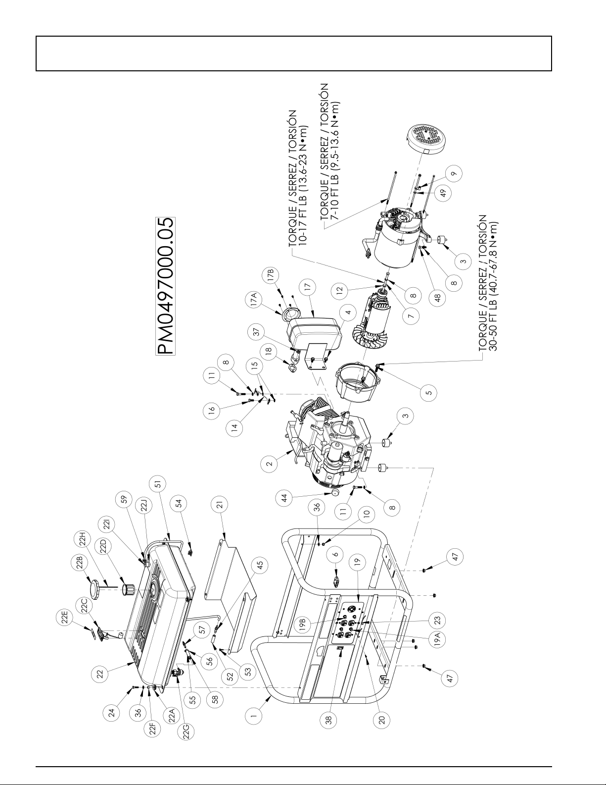
PARTS DRAWING / SCHEMA DES PIÈCES / DIAGRAMA DE PIEZAS
Page 2

9
REF. PART DESCRIPTION DESCRIPTION DESCRIPCIÓN QTY
NO. NO.
1 0069044 Carrier, assembly Ensemble transport Transportador, conjunto 1
2 Note A Engine 13 hp Honda OHV Moteur Motor 1
3 0051094 Isolator Sectionneur Aislador 4
4 0000901.01 Bolt whz 5/16-24 x .63 Boulon Perno 2
5 0057512 Bolt whz 3/8-18 x 1 1/4 Boulon Perno 4
6 0062797 Connector, panel Connecteur, tableau Conector, panel 1
7 0067521 Bolt, hex 5/16-24 x 9.75 Boulon Perno 1
8 Note B Washer, lock 5/16 Contre-écrou 5/16 Arandela, de cierre 5/16 (7,94 mm) 5
9 0008854 Lug, ground Oeillet de mise à la terre Terminal, tierra 1
10 0040832 Nut, nyloc 1/4-20 Écrous nyloc 1/4-20 Tuerca, nyloc 1/4-20 (6,35 mm) 6
11 Note B Bolt, 5/16-18 x 1 1/2 Boulon Perno 2
12 Note B Washer, flat 5/16 Rondelle plates 5/16 Arandela, plana 5/16 (7,94 mm) 5
13 0048736 Nut, nyloc 5/16-18 Écrous nyloc 5/16-18 Tuerca, nyloc 5/16-18 (7,94 mm) 4
14 0049224 Assembly, ground wire Ensemble fil de masse tressé a tierra Conjunto, cable trenzado 1
15 Note B Washer, star external 5/16 Rondelle à dents externa 5/16 Arandela, estrella 2
16 Note B Bolt, hex 5/16-18 x 3/4 Boulon, tête hex 5/16-18 x 3/4 Perno 1
17
0057664 Muffler Silencieux Silenciador 1
17A 0038984 Screen, spark arrest Crépine, pare-étincelles Malla, apagachispas 1
17B 0001537 Screw #8-32 x 3/8 Vis Tornillo 4
18 0061392 Gasket Joint Empaquetadura 1
19
0065546 Panel, wired Tableau complet câblé Panel, cabeado completo 1
19A 0049071 Circuit Breaker 20 amp Disjoncteurs 20 amp Cortacircuitos 20 A 2
19B 0049382 Circuit Breaker 30 amp Disjoncteurs 30 amp Cortacircuitos 30 A 2
20 0062020 Screw #6-19 x .50 Torx Vis Tornillo 4
21 0069062
Shield, heat Écran de chaleur Pantalla para el calor 1
22 Note C Fuel tank assembly Ensemble complet du réservoir Conjunto tanque 1
22A 0061877 Grommet Oeillet Arandela de cabo 4
22B 0065450 Fuel Cap Capuchon Tapa de combustible 1
22C 0061817 Fuel gauge/screws Jauge de carburant/vis Indicador de combustible/tornillos 1
22D 0061942 Fuel filter Filtre à carburant Filtro de combustible 1
22E 0066076 Decal, fuel gauge Décalcomanie de jauge Calcomanía de indicador 1
22F 0066072 Insert mount Insertion Inserto 4
22G 0065809 Fuel shut off Robinet de carburant Válvula combustible 1
22H 0066090 Ring, chain attachment Anneau Anillo 1
22I 0067767 Valve, rollover Soupape Válvula 1
22J 0065127 Bushing, valve Bague Buje 1
23
0055982.01 Cord Keeper
TM
Cord Keeper
TM
Cord Keeper
TM
2
24
Note B
Bolt, 1/4-20 x 1 Boulon Perno 4
25 0063191 Handle Poignée Manija 2
26 Note B Bolt, 5/16-18 x 2 1/4 Boulon Perno 2
27 Note B Washer, flat 3/8 Rondelle plates 3/8 Arandela, plana 3/8 (9,53 mm) 2
28 0063771 Wheel Roue Rueda 2
29 0055894 Rubber Foot Pied Pie 2
30 0062174 Lanyard Lanyard Acollador 2
32 Note B Bolt, 3/8-16 x 4.25 Boulon Perno 2
33 0057578 Nut, nyloc 3/8-16 Écrous nyloc 3/8-16 Tuerca, nyloc 3/8-16 (9,53 mm) 2
34 0062502 Pin, release Epingle de relâchement Alfileres de la liberación 2
35 0058955 Cap, plastic Capuchon Tapa 2
36 Note B Washer, flat 1/4 Rondelle plates 1/4 Arandela, plana 1/4 (6,35 mm) 10
37 0061393 Nut whz 8mm Écrous Tuerca 2
38 0050298 Switch, Rocker Interrupteur Interruptor 1
39 0062433 Wheel spacer Bague d’espacement Espaciador de la rueda 2
40 0062495 Grip, handle Poignée Empuñadura 2
41 0049352 Washer, flat 5/16 W Rondelle plates 5/16 large Arandela, plana 5/16 (7,94 mm) de largo 4
42 Note B Bolt, 5/16-18 x 1 Boulon Perno 2
43 0062301 Bracket, foot Support de pied Soporte del pie 1
44 0069048 Cap, vinyl dip Capuchon Tapa 1
45 0069066 Connector, hose Connecteur de flexible Conector de manguera 1
46 0063164 Spacer, handle bracket Entretoise Espaciador 2
47 0057254 Nut, hex flg 5/16-18 Écrous 5/16-18 Tuerca 5/16-18 (7,94 mm) 5
48 Note B Bolt, 5/16-18 x 1 1/4 Boulon Perno 2
49 Note B Washer, star external 1/4 Rondelle à dents externa 1/4 Arandela, estrella 1
50 Note B Bolt, 1/4-20 x 1 1/2 Boulon Perno 2
51 1130660180 Fuel hose 4.5mm ID Flexible de carburant Manguera de combustible 1
52 1130688810 Fuel hose 8mm ID Flexible de carburant Manguera de combustible 1
53 0064138 Screw #10 x 3/4 Vis Tornillo 2
54 0067624 Clip, adhesive mount Attache Presilla 2
PARTS LIST / LISTE DES PIÈCES / LISTA DE PIEZAS
Page 3

10
REF PART DESCRIPTION DESCRIPTION DESCRIPCIÓN QTY
NO. NO.
55
1130634480 Fuel hose 1/4 ID Flexible de carburant Manguera de combustible 1
56 0035857 Clamp, hose Crampon, tuyau Abrazadera, manguera 1
57 0069066 Connector, hose Connecteur de flexible Conector de manguera 1
58 0051101 Clamp, hose Crampon, tuyau Abrazadera, manguera 1
59 0050859 Clamp, hose Crampon, tuyau Abrazadera, manguera 1
60 0064546 Generator head, Sumec Tête de la génératrice, Sumec Cabezal del generador, Sumec 1
60A 0063230 Brush module Brosser le module Cepille módulo 1
60B 0063948 AVR module La tension automatique régulatrice El regulador automático del voltaje 1
60C 0063240 Cover, end Couvercle Tapa 1
PARTS LIST / LISTE DES PIÈCES / LISTA DE PIEZAS
Page 4

TOOLS REQUIRED: 7/16”, 1/2” and 9/16" sockets and ratchets, block(s) of wood (minimum of 6” tall).
Refer to the parts list on page 9.
WHEEL INSTALLATION
1. Block up end of generator opposite the fuel tank cap to install wheel kit.
2. Insert wheel spacer (item 39) into the center of the wheel (item 28).
3. Slide 3/8 x 4.25” bolt (item 32) and 3/8 washer (item 27) through the wheel (item 28), then through the wheel bracket on the
carrier, with the offset side of the wheel hub against the wheel bracket.
4. Thread 3/8 nyloc nut (item 33) onto the bolt and tighten to securely clamp the wheel assembly to the carrier.
5. Repeat above instructions for the remaining wheel.
FOOT INSTALLATION
1. Assemble the rubber feet (item 29) to the foot bracket (item 43) using a 1/4-20 x 1.5” bolt (item 11). Thread a 1/4 washer
(item 36) and a 1/4 nyloc nut (item 10) to the bolt to secure the assembly. Caution: Do not over tighten so that the foot
material collapses.
2. Blocking up the alternator side of the generator, place the foot bracket under the carrier channel. Thread a 5/16-18 x 1” bolt
(item 42) with a 5/16 wide washer (item 50) through the mounting holes and thread a 5/16 wide washer (item 50) and a 5/16
nyloc nut (item 13) to the bolt to secure the foot bracket to the carrier.
HANDLE INSTALLATION
1. Place handle (item 25) and spacer (item 46) on carrier on same end as feet, as shown in the diagram.
2. Slide 5/16 x 2.25” bolt (item 26) and 5/16 washers (item 12) through handle and spacer as shown in diagram and
secure with 5/16” nyloc nut (item 13). Tighten until handle is securely clamped to the carrier.
3. Apply aerosol hairspray or similar adhesive to the handle (item 25), and then slide the handle grip (item 40) onto the handle.
The aerosol hairspray will allow for easier assembly and will adhere the grip to the handle.
4. Insert cap (item 35) into end of handle (item 25).
5. Repeat above instructions for the remaining handle.
LOCKING HANDLE
1. Attach the lanyards (item 30) to the release pins (item 34) and
carrier as shown in the illustration.
2. To lock the handle (item 25) in the extended position, align the holes
in the handle brackets with the holes in the carrier brackets and
insert the release pins (item 34).
3
English
PORTABILITY KIT INSTALLATION
1
34
30
2
 Loading...