

Page 1
© 2007 Powermate Corporation
Stationary Standby Electric Generator
IMPORTANT SAFETY INSTRUCTIONS – Please make certain that persons who are to install, operate and
maintain this equipment thoroughly read and understand these instructions prior to operation. SAVE THESE
INSTRUCTIONS — This manual contains important instructions that should be followed during installation
and maintenance of the generator and battery.
Record the model and serial numbers of your generator below:
Model Number
____________________
Serial Number
____________________
Date Purchased
____________________
HELPLINE 1-866-769-3703
OWNERS MANUAL
MODEL SERIES: P1204
Read and understand all safety precautions in this manual and other manuals
included with this product before installing, operating and maintaining this equipment. Failure to
comply with instructions in this manual could result in personal injury, property damage, and/or
voiding of your warranty. The manufacturer WILL NOT be liable for any damage because of
failure to follow these instructions.
WARNING:
200-2667 - Revision A - 10/07
Product style and configuration may vary.
Specifications are subject to change without notice.
Page 2

200-26672
Table of Contents . . . . . . . . . . . . . . . . . . . . . . . . . . . . . . . . . . . . . . . . . . . . . . . . . . . . . . . . . . . . . . . . . . . . . 2
General Safety Instructions. . . . . . . . . . . . . . . . . . . . . . . . . . . . . . . . . . . . . . . . . . . . . . . . . . . . . . . . . . . . . . 3-4
Introduction . . . . . . . . . . . . . . . . . . . . . . . . . . . . . . . . . . . . . . . . . . . . . . . . . . . . . . . . . . . . . . . . . . . . . . . . . . 5
Unpacking Instructions . . . . . . . . . . . . . . . . . . . . . . . . . . . . . . . . . . . . . . . . . . . . . . . . . . . . . . . . . . . . . . . . . 5
Installation Planning . . . . . . . . . . . . . . . . . . . . . . . . . . . . . . . . . . . . . . . . . . . . . . . . . . . . . . . . . . . . . . . . . . . 5
Specifications . . . . . . . . . . . . . . . . . . . . . . . . . . . . . . . . . . . . . . . . . . . . . . . . . . . . . . . . . . . . . . . . . . . . . . . . 6
Installation Drawing. . . . . . . . . . . . . . . . . . . . . . . . . . . . . . . . . . . . . . . . . . . . . . . . . . . . . . . . . . . . . . . . . . . . 7
Generator Installation . . . . . . . . . . . . . . . . . . . . . . . . . . . . . . . . . . . . . . . . . . . . . . . . . . . . . . . . . . . . . . . . . . 8
Location and Generator Placement. . . . . . . . . . . . . . . . . . . . . . . . . . . . . . . . . . . . . . . . . . . . . . . . . . . . . . . . 8-9
Automatic Transfer Switch . . . . . . . . . . . . . . . . . . . . . . . . . . . . . . . . . . . . . . . . . . . . . . . . . . . . . . . . . . . . . . 10
Electrical Hookup . . . . . . . . . . . . . . . . . . . . . . . . . . . . . . . . . . . . . . . . . . . . . . . . . . . . . . . . . . . . . . . . . . . . . 11
Main Line Output Power . . . . . . . . . . . . . . . . . . . . . . . . . . . . . . . . . . . . . . . . . . . . . . . . . . . . . . . . . . . . . . . . 11
Utility Circuit Supply . . . . . . . . . . . . . . . . . . . . . . . . . . . . . . . . . . . . . . . . . . . . . . . . . . . . . . . . . . . . . . . . . . . 12
Generator Start Signal. . . . . . . . . . . . . . . . . . . . . . . . . . . . . . . . . . . . . . . . . . . . . . . . . . . . . . . . . . . . . . . . . . 12
Wiring Diagram . . . . . . . . . . . . . . . . . . . . . . . . . . . . . . . . . . . . . . . . . . . . . . . . . . . . . . . . . . . . . . . . . . . . . . . 13
Fuel Specifications & Consumption Requirements. . . . . . . . . . . . . . . . . . . . . . . . . . . . . . . . . . . . . . . . . . . . 14
Fuel Consumption Table . . . . . . . . . . . . . . . . . . . . . . . . . . . . . . . . . . . . . . . . . . . . . . . . . . . . . . . . . . . . . . . . 14
Fuel Hookup . . . . . . . . . . . . . . . . . . . . . . . . . . . . . . . . . . . . . . . . . . . . . . . . . . . . . . . . . . . . . . . . . . . . . . . . . 14
Natural Gas Settings. . . . . . . . . . . . . . . . . . . . . . . . . . . . . . . . . . . . . . . . . . . . . . . . . . . . . . . . . . . . . . . . 15
Liquid Propane Vapor Settings. . . . . . . . . . . . . . . . . . . . . . . . . . . . . . . . . . . . . . . . . . . . . . . . . . . . . . . . 15
Battery Requirements . . . . . . . . . . . . . . . . . . . . . . . . . . . . . . . . . . . . . . . . . . . . . . . . . . . . . . . . . . . . . . . . . . 16
Battery Placement and Connection. . . . . . . . . . . . . . . . . . . . . . . . . . . . . . . . . . . . . . . . . . . . . . . . . . . . . . . . 16-17
Lubrication. . . . . . . . . . . . . . . . . . . . . . . . . . . . . . . . . . . . . . . . . . . . . . . . . . . . . . . . . . . . . . . . . . . . . . . . . . . 17
First Time Startup . . . . . . . . . . . . . . . . . . . . . . . . . . . . . . . . . . . . . . . . . . . . . . . . . . . . . . . . . . . . . . . . . . . . . 18
Generator Operation . . . . . . . . . . . . . . . . . . . . . . . . . . . . . . . . . . . . . . . . . . . . . . . . . . . . . . . . . . . . . . . . . . . 18
Circuit Breaker. . . . . . . . . . . . . . . . . . . . . . . . . . . . . . . . . . . . . . . . . . . . . . . . . . . . . . . . . . . . . . . . . . . . . . . . 19
Generator Control Panel Features . . . . . . . . . . . . . . . . . . . . . . . . . . . . . . . . . . . . . . . . . . . . . . . . . . . . . . . . 19
Fuses. . . . . . . . . . . . . . . . . . . . . . . . . . . . . . . . . . . . . . . . . . . . . . . . . . . . . . . . . . . . . . . . . . . . . . . . . . . . . . . 19
Generator Control Panel Operation. . . . . . . . . . . . . . . . . . . . . . . . . . . . . . . . . . . . . . . . . . . . . . . . . . . . . . . . 20
Starting The Generator . . . . . . . . . . . . . . . . . . . . . . . . . . . . . . . . . . . . . . . . . . . . . . . . . . . . . . . . . . . . . . . . . 20
Cyclic Crank . . . . . . . . . . . . . . . . . . . . . . . . . . . . . . . . . . . . . . . . . . . . . . . . . . . . . . . . . . . . . . . . . . . . . . . . . 20
Run State . . . . . . . . . . . . . . . . . . . . . . . . . . . . . . . . . . . . . . . . . . . . . . . . . . . . . . . . . . . . . . . . . . . . . . . . . . . 20
Shutdown . . . . . . . . . . . . . . . . . . . . . . . . . . . . . . . . . . . . . . . . . . . . . . . . . . . . . . . . . . . . . . . . . . . . . . . . . . . 20
Status Indicators . . . . . . . . . . . . . . . . . . . . . . . . . . . . . . . . . . . . . . . . . . . . . . . . . . . . . . . . . . . . . . . . . . . . . . 21
Low Battery. . . . . . . . . . . . . . . . . . . . . . . . . . . . . . . . . . . . . . . . . . . . . . . . . . . . . . . . . . . . . . . . . . . . . . . 21
Engine Run. . . . . . . . . . . . . . . . . . . . . . . . . . . . . . . . . . . . . . . . . . . . . . . . . . . . . . . . . . . . . . . . . . . . . . . 21
Generator Control Panel - Faults . . . . . . . . . . . . . . . . . . . . . . . . . . . . . . . . . . . . . . . . . . . . . . . . . . . . . . . . . 21
Overcrank . . . . . . . . . . . . . . . . . . . . . . . . . . . . . . . . . . . . . . . . . . . . . . . . . . . . . . . . . . . . . . . . . . . . . . . . 21
Overspeed . . . . . . . . . . . . . . . . . . . . . . . . . . . . . . . . . . . . . . . . . . . . . . . . . . . . . . . . . . . . . . . . . . . . . . . 21
High Temperature. . . . . . . . . . . . . . . . . . . . . . . . . . . . . . . . . . . . . . . . . . . . . . . . . . . . . . . . . . . . . . . . . . 21
Low Oil Pressure. . . . . . . . . . . . . . . . . . . . . . . . . . . . . . . . . . . . . . . . . . . . . . . . . . . . . . . . . . . . . . . . . . . 21
Loss Speed. . . . . . . . . . . . . . . . . . . . . . . . . . . . . . . . . . . . . . . . . . . . . . . . . . . . . . . . . . . . . . . . . . . . . . . 21
Maintenance . . . . . . . . . . . . . . . . . . . . . . . . . . . . . . . . . . . . . . . . . . . . . . . . . . . . . . . . . . . . . . . . . . . . . . . . . 22-27
Maintenance Chart . . . . . . . . . . . . . . . . . . . . . . . . . . . . . . . . . . . . . . . . . . . . . . . . . . . . . . . . . . . . . . . . . 22
Engine Oil Level Check. . . . . . . . . . . . . . . . . . . . . . . . . . . . . . . . . . . . . . . . . . . . . . . . . . . . . . . . . . . . . . 23
Engine Oil and Oil Filter Change . . . . . . . . . . . . . . . . . . . . . . . . . . . . . . . . . . . . . . . . . . . . . . . . . . . . . . 24
Engine Oil Cooler Inspection and Cleaning . . . . . . . . . . . . . . . . . . . . . . . . . . . . . . . . . . . . . . . . . . . . . . 24
Engine Air Filter Change. . . . . . . . . . . . . . . . . . . . . . . . . . . . . . . . . . . . . . . . . . . . . . . . . . . . . . . . . . . . . 25
Battery Maintenance. . . . . . . . . . . . . . . . . . . . . . . . . . . . . . . . . . . . . . . . . . . . . . . . . . . . . . . . . . . . . . . . 25-26
Spark Plug Check. . . . . . . . . . . . . . . . . . . . . . . . . . . . . . . . . . . . . . . . . . . . . . . . . . . . . . . . . . . . . . . . . . 26
Enclosure And Site . . . . . . . . . . . . . . . . . . . . . . . . . . . . . . . . . . . . . . . . . . . . . . . . . . . . . . .
. . . . . . . . . . 27
Valve Clearance Check And Adjustment . . . . . . . . . . . . . . . . . . . . . . . . . . . . . . . . . . . . . . . . . . . . . . . . 27
Fuel System Inspection. . . . . . . . . . . . . . . . . . . . . . . . . . . . . . . . . . . . . . . . . . . . . . . . . . . . . . . . . . . . . . 27
Troubleshooting. . . . . . . . . . . . . . . . . . . . . . . . . . . . . . . . . . . . . . . . . . . . . . . . . . . . . . . . . . . . . . . . . . . . . . . 28-29
Notes. . . . . . . . . . . . . . . . . . . . . . . . . . . . . . . . . . . . . . . . . . . . . . . . . . . . . . . . . . . . . . . . . . . . . . . . . . . . . . . 30
Limited Warranty . . . . . . . . . . . . . . . . . . . . . . . . . . . . . . . . . . . . . . . . . . . . . . . . . . . . . . . . . . . . . . . . . . . . . . 31
Service Information . . . . . . . . . . . . . . . . . . . . . . . . . . . . . . . . . . . . . . . . . . . . . . . . . . . . . . . . . . . . . . . . . . . . 32
TTTTAAAABBBBLLLLEEEE OOOOFFFF CCCCOOOONNNNTTTTEEEENNNNTTTTSS
SS
Page 3
3òÿå
Do not attempt to install the generator yourself.
Extremely high and dangerous electrical voltages
are present in utility power source lines and in
generator load leads when the unit is running.
Therefore, be sure to turn OFF all power voltage
supplies at their source before attempting to
complete electrical connections. Only qualified
installation contractors or electrician’s who are
familiar with applicable codes, standards, regulations
and procedures should install the system. Improper
or unauthorized installation, operation, or service of
this equipment is extremely hazardous and may
result in serious personal injury or death.
It is NOT intended that the information in this manual
be used by any unqualified persons for the purpose
of installing a standby electric power system. This
equipment must be installed, inspected, tested and
adjusted only by qualified personnel. These people
must be familiar with the equipment and installation
requirements.
The installation of this unit must comply with the
regulations of the United States National Electric
Code (NEC) as well as state and local codes and
Occupational Safety and Health Administration
(OSHA) established in the United States.
This equipment, when installed as part of a standby
electric power system, must be installed in
conjunction with an approved transfer switch. The
transfer switch serves to prevent both generator
and utility power from being connected to the load
circuits at the same time. A properly connected
transfer switch helps to prevent backfeed of
generator power into commercial lines while the
standby generator is operating.
This generator supplies extremely high and
dangerous power voltages. Any contact with high
voltage electrically "hot" components will result in
extremely hazardous, and possibly LETHAL,
electrical shock. Use care to avoid contact with live
terminals, bare connectors, bare wires, etc.
Disconnect all power before performing maintenance
or service.
Generator exhaust air contains carbon monoxide, a
deadly odorless, colorless and tasteless gas.
Breathing carbon monoxide causes severe nausea,
fainting or death. Install the generator set outdoors
only. Do not use exhaust air to heat a room. Do not
allow exhaust air to enter a building through
windows, doors, air intakes or other means. Avoid
breathing exhaust air while installing, operating or
servicing generator set. The engine exhaust from
this product contains chemicals known to the State
of California to cause cancer, birth defects, or other
reproductive harm.
Short circuits can cause bodily injury and/or
equipment damage. Do not contact electrical
connections with tools or jewelry, make sure
clothing and shoes are dry and stand on a dry
wooden platform while adjustments are made.
Remove wristwatch, rings, and jewelry that can
cause short circuits.
GGGGEEEENNNNEEEERRRRAAAALLLLSSSSAAAAFFFFEEEETTTTYYYYGGGGUUUUIIIIDDDDEEEELLLLIIIINNNNEEEESS
SS
The following information relates to protecting YOUR SAFETY and PREVENTING EQUIPMENT PROBLEMS. To
help you recognize this information, we use the following symbols. Please read the manual and pay attention to these
sections. Also read and follow all safety labels on the engine/generator set. If labels are damaged or unreadable,
contact product service for replacements.
This is the safety alert symbol. It is used to alert you to potential personal injury hazards. Obey all
safety messages that follow this symbol to avoid possible injury or death.
Ground Location.
– A POTENTIAL HAZARD THAT WILL CAUSE SERIOUS INJURY OR LOSS OF LIFE.
– A POTENTIAL HAZARD THAT COULD CAUSE SERIOUS INJURY OR LOSS OF LIFE.
– A POTENTIAL HAZARD THAT MAY CAUSE MODERATE INJURY OR DAMAGE TO
EQUIPMENT.
NOTE: Improper installation can damage your electrical system and cause property damage, serious
personal injury or death. Installation MUST
be performed by a licensed electrician, plumber and
gas technician. Installation MUST comply with all applicable building and electrical codes.
Some areas may require building permits and/or detailed sight inspections prior to approving the
unit for operation.
NOTE: The important safety instructions appearing in this manual are not meant to cover all possible
conditions and situations that may occur. It must be understood that common sense, caution, and
care are factors which are not built into a generator, but are supplied by the person(s) installing,
maintaining, and operating it.
WARNING:
DANGER:
CAUTION:
WARNING:
Page 4
200-26674
The National Electrical Code (NEC) requires the
frame and external electrically conductive parts of
the generator to be connected to an approved earth
ground.
Keep a fire extinguisher near the generator at all
times. Extinguishers rated "ABC" by the National
Fire Protection Association are appropriate for use
on the standby electric system. Keep the
extinguisher properly charged and be familiar with
its use. If you have any question pertaining to fire
extinguishers, consult your local fire department.
Generator/engine noise can cause hearing loss.
Never operate the generator set without a muffler
or with a faulty exhaust system. Always wear
hearing protection when near or operating the
generator.
DO NOT permit anyone to operate the standby
electric system without proper instruction.
In case of accidents caused by electric shock,
immediately shut down the source of electrical
power. If this is not possible, attempt to free the
victim from the live conductor. AVOID DIRECT
CONTACT WITH THE VICTIM. Use a
nonconducting implement, such as a rope or board,
to free the victim from the live conductor. If the victim
is unconscious, apply first aid and get immediate
medical help.
Units with broken or missing parts, without
protective housing or covers should never be
operated. Contact your service center for
replacement parts.
Inspect the generator regularly, and contact your
nearest Authorized Dealer for parts needing repair
or replacement.
Never use the generator or any of its parts as a
step. Stepping on the unit can stress and break
parts, and may result in dangerous operating
conditions from leaking exhaust gases, fuel
leakage, oil leakage, etc.
Thoroughly read the OPERATORS MANUAL
before operating the generator. Safe operation and
top performance can be obtained only when
equipment is operated and maintained properly.
Ensure that enclosure doors are closed and locked
at all times other than during service.
GGGGEEEENNNNEEEERRRRAAAALLLLSSSSAAAAFFFFEEEETTTTYYYYGGGGUUUUIIIIDDDDEEEELLLLIIIINNNNEEEESSSS ((((CC
C
Coooonnnnttttiiiinnnnuuuueeeedddd))))
WARNING:
CAUTION:
Page 5
5200-2667
The stationary standby electric generator is
manufactured for our customers to supply reliable
backup power. The generator is a compact unit,
designed to supply the power for your critical needs
when utility power fails.
The standby generator will run on Liquid Propane
Gas or Natural Gas allowing flexibility for getting the
power you need. Fuel lines should be installed by a
licensed plumber or other qualified professionals or
licensed gas technician.
•About the Owners Manual
Understanding the operation of the generator is
important when using or maintaining your system. If
there are any questions about the information supplied in
this Owner’s Manuals, call our customer service helpline
number shown on the manual cover.
•About Operation or Maintenance
All required safety checks that need to be performed
are the responsibility of the operators. Listed within the
Owners Manual are safety precautions that need to be
followed to prevent personal injuries to persons around
the unit and to prevent property damage.
Immediately inspect the generator carefully for freight
loss or damage upon arrival. If loss or damage is noted
at the time of delivery, require the person making the
delivery to note the loss or damage on the freight bill, or
affix his signature under the consignor’s memo of the
loss or damage. Contact the carrier for claim
procedures.
When loss or damage is noted after delivery,
segregate the damaged material, and contact the carrier
for claim procedures. Be sure to retain the packaging
material for carrier inspection.
“Concealed Damage” is understood to mean damage
to the contents of a package which is not evident at the
time of delivery by the carrier, but which is discovered
later. The carrier or carriers are responsible for
merchandise lost or damaged in transit. The title to
goods rests with the consignee when generators are
shipped F.O.B. factory, and only the consignee can
legally file a claim.
After inspecting the generator, engine and enclosure
for physical damage, finish reading the Operating and
Maintenance Instructions. These manuals contain
important safety information.
Taking a few moments to pre-plan before beginning
installation of the generator can provide significant
savings in materials and labor and lower future
maintenance. Some items to consider in planning
generator installation are safe generator operation, use
of an Automatic Transfer Switch, load requirements,
generator location, fuel supply, environmental conditions
and applicable local, regional or national codes. Some
areas may require building permits and/or detailed site
inspections prior to approving the unit for use. Check
with local authorities before starting installation.
Installation of a standby engine/generator system is
complex and should not be considered a Do-It-Yourself
project. Safe installation requires the skill and knowledge
of licensed electrician's and plumbers or gas technicians.
Contact an authorized dealer for assistance with
installation planning and referral to properly qualified,
licensed installing contractors.
IIIINNNNTTTTRRRROOOODDDDUUUUCCCCTTTTIIIIOOOONN
NN
UUUUNNNNPPPPAAAACCCCKKKKIIIINNNNGGGG IIIINNNNSSSSTTTTRRRRUUUUCCCCTTTTIIIIOOOONNNNSS
SS
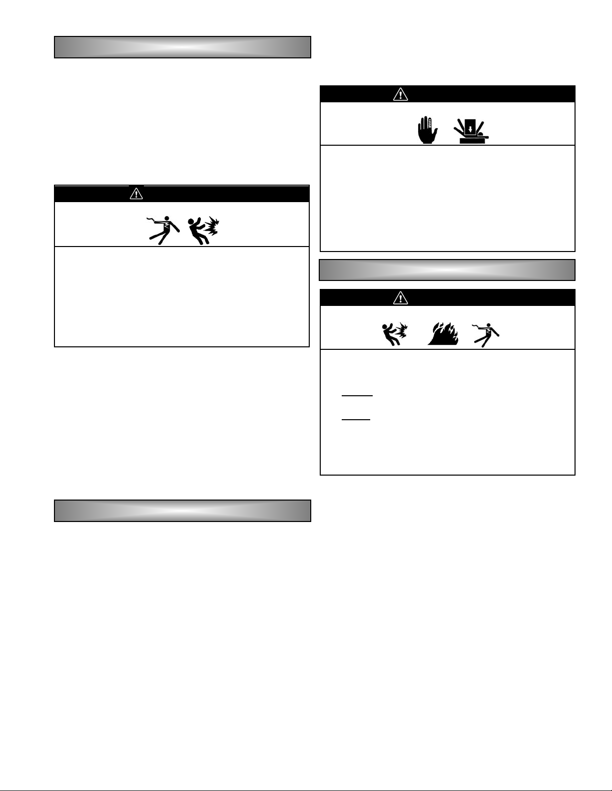
RISK OF INJURY AND BEING CRUSHED
• HEAVY EQUIPMENT. Unbalanced weight.
Improper lifting can cause severe injury or
death and equipment damage.
• When lifting the generator or using hoisting
equipment, be careful not to touch overhead
power lines. Proper tools and equipment and
qualified personnel should be used in all
phases of handling and unpacking.
WWAARRNNIINNGG
RISK OF ELECTROCUTION AND/OR INJURY
• The installation of this equipment must be done
by licensed electrician's, contractors and gas
technicians or plumbers. Installation must be
completed in conformance with NEC and local
electrical and building codes. Some areas may
require building permits and/or detailed sight
inspections prior to approving the unit for
operation.
WWAARRNNIINNGG
IIIINNNNSSSSTTTTAAAALLLLLLLLAAAATTTTIIIIOOOONNNN PPPPLLLLAAAANNNNNNNNIIIINNNNGG
GG
RISK OF INJURY
• Improper installation can damage your
electrical system and cause property damage,
serious personal injury or death. Installation
MUST be performed by a licensed electrician
and plumber or gas technician. Installation
MUST
comply with all applicable building and
electrical codes. Some areas may require
building permits and/or detailed sight
inspections prior to approving the unit for
operation.
DDAANNGGEERR
Page 6

200-26676
GGGGEEEENNNNEEEERRRRAAAATTTTOOOORRRR SSSSPPPPEEEECCCCIIIIFFFFIIIICCCCAAAATTTTIIIIOOOONNNNSS
SS
P120401 (12 KW)
Rated Wattage - (Standby) @1.0 PF LPG * 12,000
Rated Wattage - (Standby) @1.0 PF NG * 9,800
Voltage 120/240 volts
Rated Current 100/50 amps LPG
Frequency 60 HZ
Power Factor 1.0
Max. Ambient Temp Rise 105°C
Insulation class H
Engine Subaru EH72
Engine Type Air cooled V-twin (2 cylinders)
RPM 3600
Displacement cc (c.i.d) 43.9 cu. in. (720 cm³)
Bore X Stroke mm (inches) 2 - 3.31 in. x 2.56 in. (84 mm x 65 mm)
Compression Ratio 8:1
Valve arrangement Overhead valve
Governor Centrifugal Flyweight Type
Ignition system Flywheel Magneto (Solid State)
Starter Electric Starter
Alternator 12vdc
Oil Capacity (w/o filter) 1.5 qts (1.42L)
Oil Capacity (with filter) 1.8 qts (1.70L)
Oil Filter See Engine Manual
Cooling System Forced Air
Spark plug NGK BPR6ES
Battery BCI Group 26 or 26R, minimum 450 CCA
Air filter See Engine Manual
Minimum Content Requirements for Natural Gas (NG) ** 1000 BTU’sper cubic foot
Minimum Content Requirements for Liquid Propane Vapor (LPG) ** 2520 BTU’s per cubic foot
Consumption at Full Load for Natural Gas (NG) 315 cubic feet per hour
Consumption at Full Load for Liquid Propane Gas (LPG) 3.99 gallons per hour
Dimensions (see next page for installation drawing) 47”L x 29”W x 31”H
Shipping Weight 550
Normal Operating Range -20°F (-28.8°C) to 104°F (40°C)
* Note: Rated wattage is specified at sea level, 60°F ambient temperature, and propane fuel (with 2500 BTU/cuft). Rated wattage decreases
approximately 3.5% for each 1000ft above sea level and approximately 1% for each 10°F above 60°F ambient temperature.
** Fuel supply pressures must be between 4 oz (6” w.c.) and 6 oz (11” w.c.) at inlet to the unit.
Page 7
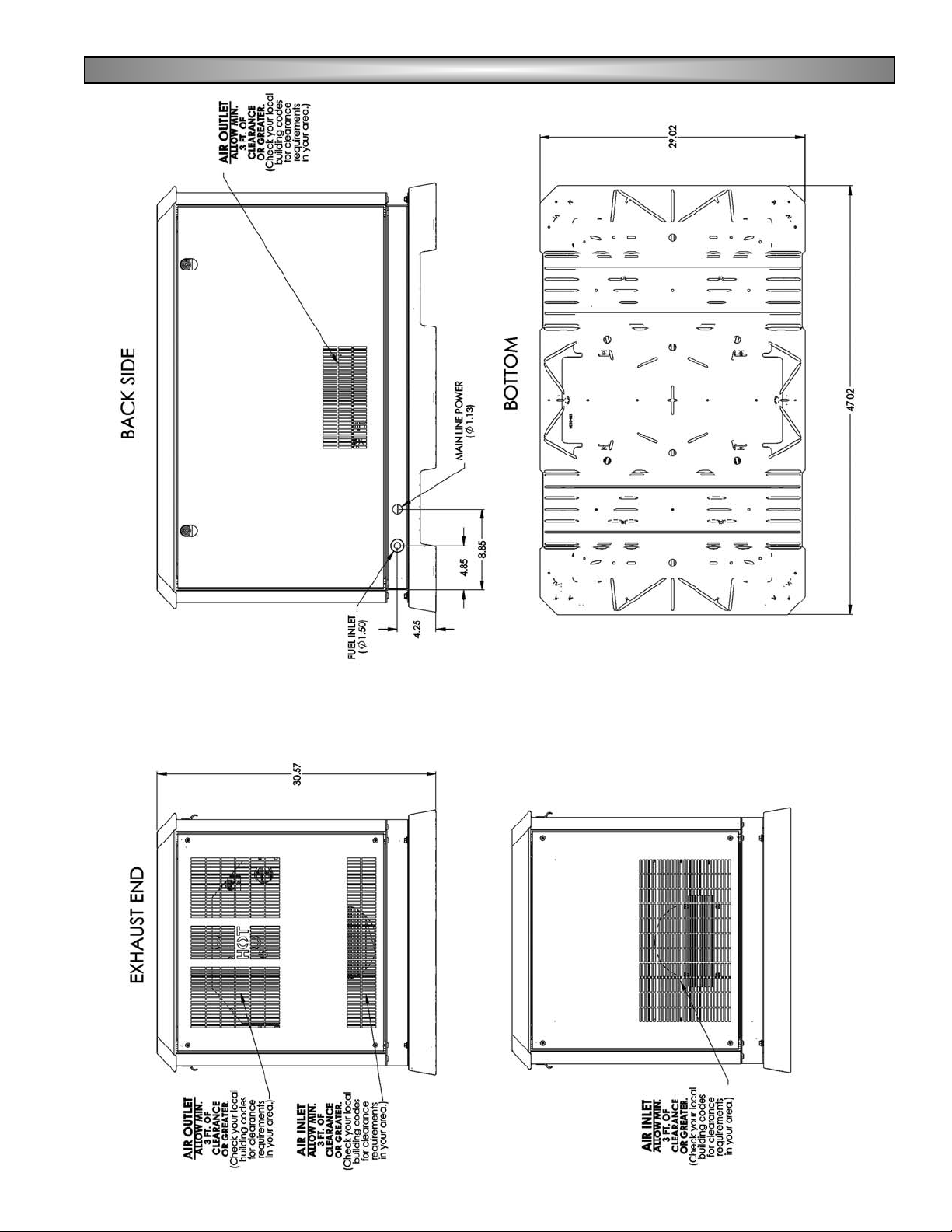
IIIINNNNSSSSTTTTAAAALLLLLLLLAAAATTTTIIIIOOOONNNN DDDDRRRRAAAAWWWWIIIINNNNGGGGSS
SS
7200-2653
Page 8
200-26678
Once installation planning is complete and all
necessary local permits are granted, installation of the
generator may begin. Within the following section
general recommendations are given for installing the
generator. However, installations are affected by local
site conditions, regional construction practices, material
availability, local or regional codes and/or other
variables. Therefore, recommendations included in this
manual are provided as a guide only and are not meant
to serve as detailed installation plans. All decisions
regarding installation and materials are at the discretion
of the licensed electrician's and licensed plumbers
performing the installation and/or the inspector
performing the final inspection as required by local or
regional code. Additionally, illustrations provided in this
manual are subject to ongoing revisions and shall not be
construed as blueprints.
For proper ventilation and maintenance, locate the
generator outdoors in an area that will allow a minimum
of three feet or more of clearance between the generator
and any other structure. Note: Check your local
building codes for clearance requirements for your
area.
When placing the generator, the direction of the
exhaust should be pointing away from windows, doors
and any ventilation system.
Insure that sufficient air flow is available to remove
the exhaust fumes and cool the generator properly.
NOTE: It would be extremely difficult, if not impractical,
to attempt a detailed coverage of every
installation possibility. For that reason, much of
the information is general in nature. Plan the
installation carefully. Information in this manual is
provided as a guide only and is not meant to
serve as a detailed installation plan. Illustrations
provided in the manual must not be construed as
blueprints.
NOTE: The generator has an engine fan that draws the
air in from the end panel slots, circulates it within
the enclosure and forces the air through the
side panels and the exhaust panel slots.
All local applicable codes, standards and regulations
must be followed for the installation of the generator.
Some areas may require building permits and/or detailed
sight inspections prior to approving the unit for use.
NOTE: Utility wiring from the house to power the
battery charger and other start assisting
components should be tightened on the
identified terminal block at a torque of 20 lbin. The wire size is to be selected according
to allowable ampacities given in Table 310-16
of the National Electric Code.
Signal wiring from the transfer switch is to be
18AWG multi-strand wire tightened on the
identified terminal block to a torque of 20 lb-in.
Power leads from the generator/circuit
breaker being wired to the transfer switch
should be tightened in the identified terminal
block to 120 lb-in. The wire size is to be
selected according to allowable ampacities
given in Table 310-16 of the National Electric
Code.
Field wiring of this unit must be conducted
by a licensed electrician.
CCAAUUTTIIOONN
• Covering or restricting the air passages on the
generator will cause the unit to overheat and
may create a fire hazard. Do not allow snow or
leaves to cover enclosure openings.
• Leave a three foot or greater open area around
all sides of the unit. Check your local building
codes for clearance requirements for your area.
Do not plant trees or plants close to the unit.
• Unit should be located such that it prevents
combustible material from accumulating under
the generator set.
GGGGEEEENNNNEEEERRRRAAAATTTTOOOORRRR IIIINNNNSSSSTTTTAAAALLLLLLLLAAAATTTTIIIIOOOONN
NN
LLLLOOOOCCCCAAAATTTTIIIIOOOONNNN AAAANNNNDDDD GGGGEEEENNNNEEEERRRRAAAATTTTOOOORR
RR
PPPPLLLLAAAACCCCEEEEMMMMEEEENNNNTT
TT
WWAARRNNIINNGG
• Hazardous voltage can cause severe injury or
death. Electrocution is possible whenever
electricity is present. Open the main circuit
breaker of all power sources before servicing
the equipment. Configure the installation to
electrically ground the generator set, transfer
switch and related equipment and electrical
circuits to comply with applicable codes and
standards. Never contact electrical leads or
appliances when standing in water or on wet
ground because these conditions increase the
risk of electrocution.
• The exhaust from this product is extremely hot
and remains hot after shutdown. High grass,
weeds, brush, leaves, or other combustible
materials, must remain clear of the exhaust.
Such materials may ignite and burn from the
heat of the exhaust system.
DDAANNGGEERR
• The generator engine exhaust fumes contain
carbon monoxide, which can be DEADLY. This
dangerous gas, if breathed in sufficient
concentrations, can cause unconsciousness or
even death. The generator must be installed
properly, in strict compliance with applicable
codes and standards. Following installation,
you must do nothing that might render the
generator unsafe or in noncompliance with
such codes and standards.
Page 9
9200-2667
The generator is supplied with an integral molded
plastic base for use as an installation pad. Use of this
base is intended to minimize installation cost by
eliminating the need for a poured concrete pad.
A pad of crushed gravel a minimum of three inches
thick is recommended as a base to set the generator on.
Compact the gravel and ensure that the pad is level in all
directions, making sure that the overall pad height is
greater than the surrounding grade with a slope to carry
water away from all sides of the pad. Pad dimensions at
least six inches larger than the base size in all directions
are recommended.
It is possible to use a standard concrete pad if
desired. When using this method, a lightly steel
reinforced pad a minimum of 2 inches thick, poured to
local codes is recommended. Ensure the pad extends
past the generator pallet and is high enough to promote
drainage of water away from the generator.
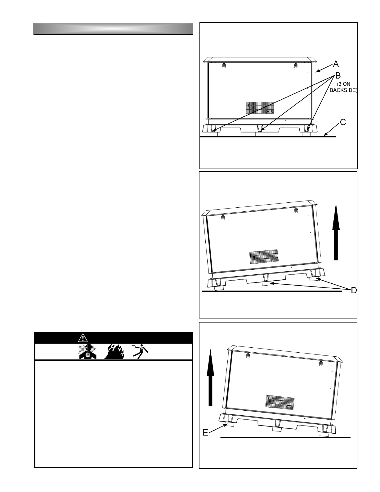
After preparing the base pad (C), position the
generator (A) directly on the pad , complete with the
wooden skids supplied for shipping. Remove the lag
bolts (B) fastening the wood to the pallet from all six
positions. Using a pry bar with a block of wood as a
pivot, carefully lift one end of the pallet and remove the
wooden skids from both that end and the center of the
pallet (D). Lower the pallet to the pad, then pry the other
end up and remove the skid from that end (E). Check
the generator with a level in all directions, placing
material under the base as required.
Although the weight of the generator is adequate to
prevent movement during normal operation, anchoring of
the generator is recommended. To anchor the generator
on a gravel pad, drive a minimum of four (4) spikes
through the anchoring tabs located on the outside
corners of the pallet. If a concrete pad is used, anchor
the pallet at the same points using appropriate concrete
fasteners.
PPPPLLLLAAAACCCCEEEEMMMMEEEENNNNTTTT AAAANNNNDDDD AAAANNNNCCCCHHHHOOOORRRRIIIINNNNGG
GG
WWAARRNNIINNGG
• For fire safety, the generator must be installed
and maintained properly. Installation always
must comply with applicable codes, standards,
laws and regulations. Adhere strictly to local,
state and national electrical and building codes.
Comply with regulations the Occupational
Safety and Health Administration (OSHA) and
National Electrical Code (NEC) have
established.
• This generator is designed to be installed
outside only. Never install this unit inside any
room, enclosure, or basement. The generator
needs adequate cooling and ventilation for
continued proper and safe operation.
Page 10
200-266710
When connecting the generator to a building
electrical distribution system, use of a transfer switch is
recommended to isolate the normal utility source from
the generator supply. By preventing backfeed of the
generator power into the utility lines during a utility power
outage, the switch provides a level of safety for electrical
line workers. An automatic transfer switch listed to
Underwriters Laboratories Standard 1008 performs this
function while also supplying a method to automatically
start and stop the generator set and transfer power to the
building electrical system from an appropriate source.
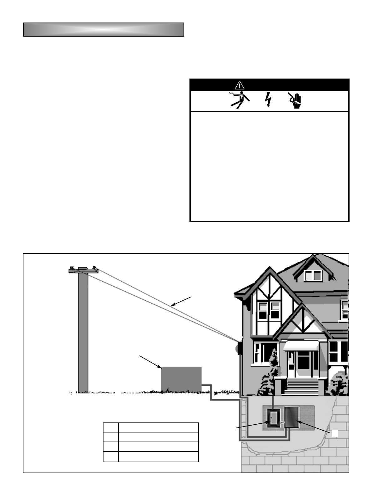
When planning for a transfer switch/generator
installation, it is necessary to know the method of
interconnection to the building system. As illustrated, it is
recommended to connect the generator to power only
circuits that are necessary during a power outage. When
following this method, the transfer switch feeds only the
necessary circuits. Another option is to connect the
transfer switch directly to the entire building electrical
distribution system. In this case, all circuits or loads must
be controlled to avoid overloading and possibly
damaging the generator set.
Switch selection is based on factors such as the size
of the building distribution system, available generator
power and required generator control system. Due to the
complex nature of electrical distribution systems, the
sizing, selection and installation of a switch is best
handled by a licensed electrician or qualified standby
generator dealer. Any switch installation must be
performed by a licensed electrician to the instructions of
the switch manufacturer and any applicable local,
regional or national codes.
AAAAUUUUTTTTOOOOMMMMAAAATTTTIIIICCCC TTTTRRRRAAAANNNNSSSSFFFFEEEERRRR SSSSWWWWIIIITTTTCCCCHH
HH
Example of Recommended Transfer
Switch Installation
(Main Panel Load)
A
B
C
D
A Utility Power
B Standby Generator
C Main Circuit Panel
D Automatic Transfer Switch
WWAARRNNIINNGG
• Hazardous "backfeed" voltage can cause
severe injury or death. Install a transfer switch
in standby power installations to prevent
connection of standby and other sources of
power. Electrical backfeed into a utility
electrical system can cause serious injury or
death to utility personnel working on
transmission lines.
• Do not try MANUAL operation of the transfer
switch until all power supplied to the switch has
been positively turned OFF. Failure to turn OFF
power supplied may result in extremely
dangerous and possibly lethal electrical shock
or arching.
Page 11

11200-2667
Once the generator is anchored in its final position, it
is ready for electrical connections. The generator is
supplied with two terminal blocks for connection of three
distinct electrical circuits; main line output power, utility
power input and generator start signal. Main line output
power is the electrical output of the generator, utility input
powers the battery charger and optional block heater
devices and the generator start signal is the interface
with an Automatic Transfer Switch that allows the
generator to operate automatically upon a utility power
outage.
The output circuit of the generator is 4-wire, 240V,
rated for the amperage as shown on the generator
nameplate. Connection to the transfer switch requires
two leads, commonly referred to as "hot" leads (L1 & L2),
a neutral (N), and ground lead. Positions of these leads
are labeled on the main line output terminal block, also
shown in Fig. A. Select proper power output wire
sizes according to allowable ampacities given in
Table 310-16 of the latest revision of The National
Electric Code(NFPA 70). To connect the wires, strip
the insulation back approximately ½" from the end of the
wire, insert the stripped end into the terminal block, then
torque the terminal block screw to 35 in-lbs (4.0 N-m).
EEEELLLLEEEECCCCTTTTRRRRIIIICCCCAAAALLLLHHHHOOOOOOOOKKKKUUUUPP
PP
WWAARRNNIINNGG
• In case of accidents caused by electric shock,
immediately shut down the source of electrical
power. If this is not possible, attempt to free the
victim from the live conductor. AVOID DIRECT
CONTACT WITH THE VICTIM. Use a
nonconducting implement, such as a rope or
board, to free the victim from the live
conductor. If the victim is unconscious, apply
first aid and get immediate medical help.
DDAANNGGEERR
• Improper installation can damage your
electrical system and cause property damage,
serious personal injury or death. Installation
MUST be performed by a licensed electrician
and plumber, or gas technician and installation
MUST comply with all applicable building and
electrical codes. Some areas may require
building permits and/or detailed sight
inspections prior to approving the unit for
operation.
MMMMAAAAIIIINNNN LLLLIIIINNNNEEEE OOOOUUUUTTTTPPPPUUUUTTTT PPPPOOOOWWWWEEEERR
RR
Fig. A
FIELD CONNECTIONS
TO BE PERFORMED BY A
LICENSED ELECTRICIAN
Page 12

200-266712
A receptacle is provided with the generator to power
the battery charger for reliable starting. It is also
intended to power an optional block heater if that option
is desired. Connection of this circuit to a power supply
that is only present when normal utility power is supplied
is recommended. By connecting the receptacle in this
fashion, it is possible to insure that neither the battery
charger or block heater are on while the engine is
running. Precautions are engineered into the generator
to prevent these occurances but connection of the circuit
in this fashion provides an additional fail-safe method of
engine and battery protection.
Input to the utility circuit is 3-wire, 120V, 15A.
Connections include a "hot" lead (L1), neutral (N) and
ground lead. Positions of the incoming wire connections
are labeled at the auxiliary connection block, shown in
Fig. B . Select proper utility supply wire size
according to allowable ampacities given in Table
310-16 of the latest revision of The National Electric
Code(NFPA 70). To connect the wires, strip the
insulation back approximately ¼" from the end of the
wire, insert the stripped end under the screw and washer
on the terminal block, then torque the terminal block
screw to 20 in-lbs (2.3 N-m).
When the control panel mode switch is placed in the
AUTO position, generator starting and stopping is
controlled by the opening or closing of a set of voltage
free contacts. Two wires from those contacts are
connected to the generator through the auxiliary
connection block shown in Fig. B. Use of a twisted pair of
stranded copper wire no smaller than AWG 18 gage is
recommended. To insure proper operation of the auto
start feature, use a transfer switch offering “close-to-run
control contacts. To connect the wires, strip the
insulation back approximately ¼" from the end of the
wire, insert the stripped end under the screw and washer
on the terminal block, then torque the terminal block
screw to 20 in-lbs (2.3 N-m).
NOTICE: A field-installed conductor is not required
to be separated from a field wiring terminal of a
different circuit when the field wiring is insulated for
the maximum voltage of either circuit and both
circuits are Class 2 or Class 3, or both circuits are
other than Class 2 or Class 3.
GGGGEEEENNNNEEEERRRRAAAATTTTOOOORRRR SSSSTTTTAAAARRRRTTTT SSSSIIIIGGGGNNNNAAAALL
LL
UUUUTTTTIIIILLLLIIIITTTTYYYYCCCCIIIIRRRRCCCCUUUUIIIITTTT SSSSUUUUPPPPPPPPLLLLYY
YY
Fig. B
FIELD CONNECTIONS
TO BE PERFORMED BY A
LICENSED ELECTRICIAN
Page 13

13200-2667
WWIIRRIINNGG DDIIAAGGRRAAMM
Page 14

200-266714
The engine driving the generator is engineered to
provide reliable power on either Liquefied Propane Vapor
(LPG) or Natural Gas. For proper operation on these
fuels, it is important to deliver gas with adequate energy
content, at sufficient pressure and flow rate. This
generator is designed to operate on Liquefied Propane
Vapor (LPG) with a minimum energy content of 2500
BTU per cubic foot or Natural Gas with a minimum
energy content of 1000 BTU per cubic foot. This
generator is designed to operate with a fuel pressure at
the inlet of the unit between 6 and 11 inches of water
column (4-6 ounces).
Required fuel flow rates for specific models are given
in the table below. To insure correct sizing of the piping
supplying fuel to the generator set, provide the flow and
pressure requirements of this section to a fuel supplier or
licensed plumber during the installation planning stage. If
the fuel supplier cannot guarantee delivery of fuel with
these properties, the generator may not perform as
advertised.
Due to differences in the energy content of fuel used,
it is necessary to derate the output of the generator when
connected to Natural Gas. Additionally, regional and/or
seasonal variations in the makeup of the fuel can further
affect output of the engine/generator system. When
using Natural Gas fuel with minimum properties as
defined, engine output can fall approximately 10% below
that of the same set using Propane Vapor.
Per the National Gas Code (NFPA 54 - ANSI
2223.1), a manual shutoff valve in the fuel supply line
to the generator is recommended.
FUEL REQUIREMENTS:
For the best operation of the unit, the fuels used
should have a minimum content of 1000 BTU’s per cubic
foot for Natural Gas (NG) and 2520 BTU’s per Cubic foot
for Liquid Propane vapor (LPG). Contact local fuel
supplier for local BTU content. Fuel supply pressures
must be between 4oz (6” H
2
0 per square inch) and 6oz
(11” H
2
0 per square inch) at the inlet to the unit.
After electrical connections are complete, the next
installation step is to connect a fuel supply to the unit.
The fuel inlet fitting supplied with the generator is male
3/4" NPT. To accommodate potential settling of the
generator relative to rigid supply pipeline, use of a
flexible line, provided by manufacturer, in the supply line
is suggested. When making connections, use only
materials rated for the fuel supplied and approved for use
by local, regional or national codes and/or regulatory
agencies.
FFFFUUUUEEEELLLLSSSSPPPPEEEECCCCIIIIFFFFIIIICCCCAAAATTTTIIIIOOOONNNNSSSS AAAANNNNDD
DD
CCCCOOOONNNNSSSSUUUUMMMMPPPPTTTTIIIIOOOONNNN RRRREEEEQQQQUUUUIIIIRRRREEEEMMMMEEEENNNNTTTTSS
SS
WWAARRNNIINNGG
• Natural gas (NG) is highly explosive.
• Natural gas (NG) is lighter than air and will
collect in high places.
• Liquid propane vapor (LPG) is highly explosive.
• Liquid propane vapor (LPG) is heavier than air
and will collect in lower places.
• Extreme caution should be taken when working
on a new installation or while performing
general maintenance.
• Do not smoke when near the unit.
• Keep flames, sparks, pilot lights, arc-producing
equipment, switches and all other sources of
ignition well away. Keep a type ABC fire
extinguisher handy.
• Potential for fire or explosion always exist when
using natural gas (NG) or liquid propane vapor
(LPG) as a fuel source. Install this unit in
compliance with all local fuel codes.
• Do Not operate engine if smell of fuel is present
or other explosive conditions exist.
DDAANNGGEERR
FFFFUUUUEEEELLLLHHHHOOOOOOOOKKKKUUUUPP
PP
DDAANNGGEERR
• All fuel system installations MUST BE done by a
licensed plumber or licensed gas technician
and must comply with all applicable codes,
standards and regulations.
WWAARRNNIINNGG
• Natural Gas and Propane Vapor are highly
explosive gases. Check ALL fuel system
connections for leaks before starting
engine/generator set.
• DO NOT use a flame to check for leaks.
• Use approved equipment and methods to check
for leaks.
FUEL CONSUMPTION TABLE
P120401
Fuel Consumption (@100%
load)
3.44 Gal/Hr (LP)
280 Cu-ft/Hr (NG)
All values reflect consumption at 100% rated output.
• All fuel system installations MUST BE done by a
licensed plumber or licensed gas technician
and must comply with all applicable codes,
standards and regulations.
Page 15

15200-2667
Units are tested with natural gas before they leave
the factory. If natural gas is to be used, no adjustments
are required.
When supplying natural gas as the operating fuel,
provide fuel with a minimum of 1000 BTU/ft
3
at inlet
pressures between 6" and 11" of water column (4 - 6
oz). Failure to meet these minimums will cause the
generator to run poorly and/or may limit output to values
below nameplate value. If fuel with these qualities is not
available, contact the customer service center.
Refer to the Fuel Consumption Table on page 14 for
fuel flow requirements for the unit installed. Size all
feeding piping to deliver sufficient flow above the
minimum pressure of 6" water column (4 oz).
Per the National Gas Code (NFPA 54 - ANSI
2223.1), a manual shutoff valve in the fuel supply line
to the generator is recommended.
In cases where liquefied propane vapor is selected
as the fuel of choice, insure fuel delivery in the gaseous
state, with a minimum energy content of 2500 BTU/ft3,
at inlet pressures between 6" and 11" of water
column (4 - 6 oz). Fuel below these specifications may
cause improper engine operation and/or failure to deliver
rated generator output. Size all fuel system plumbing to
provide fuel flow as given in the Fuel Consumption
Table on page 14, at a minimum pressure of 7" water
column (4 oz).
After completing external supply connections, follow
the instructions listed below to change over to LPG.
1. Remove the front panel by inserting the key into the
locks located on top of the panel. and turn 1/4 turn
counterclockwise to unlock. Lift the panel up and out
of the base and set it aside.
2. Remove the air filter cover (A by turning the air filter
cover nut (B) counterclockwise.
3. Remove the air filter (C).
4. Remove the 3 bolts (10mm) (D from the air filter
base (E) and set it aside. Note: be careful not to drop
the bolts into the carburetor.
5. Loosen the fuel hose clamp (F) and remove the fuel
hose (G).
6. Insert the orifice (H) (included) and tighten by
turning clockwise.
7. Put the fuel hose and clamp back on and tighten the
clamp.
8. Place the air filter base back onto the carburetor and
tighten the 3 bolts.
9. Place the air filter back onto the center stud.
10. Replace the air filter cover and air filter nut and
tighten.
11. Install the panels back onto the generator by placing
the bottom of the panel onto the base and pushing it
up into place. Lock the panel by inserting the key into
the locks and turning 1/4 turn clockwise.
Natural Gas (NG)
Propane Vapor (LPG)
Page 16

200-266716
To insure reliable starting in most weather
conditions, it is important to properly match a battery to
the requirements of the generator. The generator uses a
12 Volt, direct current, negative ground control system
powered by an automotive style lead acid battery.
Successful engine starting is dependent upon the
cranking speed of the engine, which in turn is affected by
the cranking capacity of the battery. When selecting a
battery, choose the model that provides the highest
available cold cranking amperes (CCA) within a given
size range, as specified by the Battery Council
International (BCI). The battery tray and cables supplied
with the generator are sized to accept a BCI Group 26
or 26R battery, with a minimum recommended rating of
450 CCA.
The next step in installation of the generator is
placement and connection of the engine cranking
battery. Provided battery cables are sized to accept a
BCI Group 26 or 26R automotive style battery. A
battery with a minimum of 450 CCA (cold cranking
amperes) in this size range is recommended to assure
reliable engine starting.
BBBBAAAATTTTTTTTEEEERRRRYYYYRRRREEEEQQQQUUUUIIIIRRRREEEEMMMMEEEENNNNTTTTSS
SS
BBBBAAAATTTTTTTTEEEERRRRYYYYPPPPLLLLAAAACCCCEEEEMMMMEEEENNNNTTTT AAAANNNNDD
DD
CCCCOOOONNNNNNNNEEEECCCCTTTTIIIIOOOONN
NN
The electrolyte is a dilute sulfuric acid that is
harmful to the skin and eyes. It is electrically
conductive and corrosive. The following procedures
are to be observed.
• Wear full eye protection and protective
clothing.
• Where electrolyte contacts the skin, wash it
off immediately with water.
• Where electrolyte contacts the eyes, flush
thoroughly and immediately with water and
seek medical attention.
• Spilled electrolyte is to be washed down with
and acid neutralizing agent. A common
practice is to use a solution of one pound
(500 grams) bicarbonate of soda to one
gallon (4 liters) of water. The bicarbonate of
soda solution is to be added until the
evidence of reaction (foaming) has ceased.
The resulting liquid is to be flushed with
water and the area dried.
A battery presents a risk of electrical shock and a
high short circuit current. The following precautions
are to be observed when working on batteries:
• Remove watches, rings or other metal
objects.
• Use tools with insulated handles.
• Wear rubber gloves.
• Do not lay tools or metal parts on top of
batteries.
• Disconnect charging source prior to
connecting or disconnecting battery
terminals.
• Determine if the battery is inadvertently
grounded. When inadvertently grounded,
remove source of ground. Contact with any
part of a grounded battery is capable of
resulting in electrical shock. The risk of such
shock is reduced when such grounds are
removed during installation and
maintenance.
• Failure to connect and disconnect in the
proper sequence can cause equipment
damage. Ensure there is a clean tight fit from
the cables to the post.
WWAARRNNIINNGG
CCAAUUTTIIOONN
WWAARRNNIINNGG
Lead-acid batteries present a risk of fire because
they generate hydrogen gas. The following
procedures are to be followed:
• Do not smoke when near batteries.
• Do not cause flame or spark in battery area.
• Discharge static electricity from body before
touching batteries by first touching a
grounded metal surface.
• Do not dispose of batteries in a fire. The
battery is capable of exploding.
• Do not open or mutilate the battery or
batteries. Released electrolyte has been
known to be harmful to the skin and eyes
and to be toxic.
• Make sure the control panel Mode switch is in
the OFF position before connecting the battery
cables. Failure to do so may result in
unexpected engine starting and to personal
injury.
WWAARRNNIINNGG
Page 17

17200-2667
To access the battery and charger, remove the front
and back panels by inserting the key into the locks
located on top of the panel. and turn 1/4 turn
counterclockwise to unlock. Lift the panels up and out of
the base and set it aside.
Place the battery (A) on the base as shown in Fig G.
After the battery is set, begin attaching the battery
cables to the battery posts, starting with the positive (+),
or red, cable (B). Loosen the bolt (C) on the post clamp
slightly to allow the clamp to expand, then firmly push the
clamp onto the battery post marked positive (+) until the
top of the post extends past the top of the clamp. Rotate
the clamp around the post as required to insure the
clamp cannot contact any metal components, then
tighten the clamp bolt (C) until snug. Finally,slide the
post boot (D) down the cable and place it entirely over
the clamp.
Finish connecting the battery by placing the negative
(-), or black, battery cable (E) to the battery post marked
negative (-). Push the clamp firmly over the post until the
post extends past the top of the clamp, then rotate the
clamp to avoid contact with any metal parts. Tighten the
battery clamp bolt (F) until snug.
The final step of battery installation is to verify proper
connection of all battery charger connections. A battery
charging system (G) is included with the
engine/generator set to maintain the battery charge
during extended periods of generator inactivity, therefore
providing consistent starting. A quick check of charger
connections will verify that factory connections are
correct so the charger can function as intended. Insure
that the charger is connected by checking to see that it is
plugged into a powered receptacle, and that the positive
(+) and negative (-) charger cables are connected to their
respective battery cables.
Install the panels back onto the generator by placing
the bottom of the panel onto the base and pushing it up
into place. Lock the panel by inserting the key into the
locks and turning 1/4 turn clockwise.
Once all connections are made, the final installation
step is verification of proper engine oil level. Check oil
level before start-up (see page 23 for instructions). The
unit is shipped with the proper type of oil in the
crankcase for operation above 40°F. Follow the engine
manufacturer’s recommendations for oil at temperatures
below 40°F. Check oil periodically to ensure that the unit
is properly lubricated. Follow the engine manufacturer’s
recommended service schedule.
Engine oil capacity is 1.2 qt (1.14L) without a filter
change and 1.5qt (1.42L) with a filter change.
BBBBAAAATTTTTTTTEEEERRRRYYYYPPPPLLLLAAAACCCCEEEEMMMMEEEENNNNTTTT AAAANNNNDD
DD
CCCCOOOONNNNNNNNEEEECC
C
CTTTTIIIIOOOONNNN ((((ccccoooonnnntttt....))))
LLLLUUUUBBBBRRRRIIIICCCCAAAATTTTIIIIOOOONN
NN
FIG. G
WWAARRNNIINNGG
• State and federal agencies have determined
that contact with used engine oil can cause
cancer or reproductive toxicity. Take care to
limit skin contact and breathing of vapors as
much as possible. Use rubber gloves and wash
exposed skin.
CCAAUUTTIIOONN
• Too much oil can cause high oil consumption,
high operating temperatures and oil foaming.
Too little oil can cause severe engine damage.
Keep the oil level between the full and add
marks on the dipstick.
• Any attempt to crank or start the engine before
it has been properly serviced with the
recommended oil will result in an engine failure
that is not covered under warranty.
• Never run this equipment without the complete
air cleaner system installed on the engine.
Failure to do so will result in premature engine
wear and significantly reduced engine life.
Page 18

200-266718
After completing all installation procedures, read and
understand the operating instructions for the generator
controller. Know how the control panel operates, what to
expect when activating control panel switches and how
to shut the generator off in the event of an emergency.
Before starting the generator for the first time, check off
all items on the following list, then follow the given
procedure to verify correct operation of the generator.
Is unit level?
Is adequate free air space (3 feet minimumor
greater,check your local building codes for clearance
requirements for your area.) available on all sides of
the enclosure?
Are all cabinet openings free from blockage?
Is the exhaust directed away from dwellings, dwelling
air intakes, or combustible materials?
Are the fuel supply lines and internal generator fuel
connections leak-free?
Is fuel supply pressure within specifications?
Is the regulator connection properly configured for
the fuel supplied?
Is an approved transfer switch used to prevent
backfeed into utility lines?
Are electrical connections tight, and properly
connected?
Are electrical conductors sized properly?
Is a properly sized engine cranking battery correctly
installed?
Is the battery maintenance charger plugged in and
operating correctly?
Are all protective covers installed and tightened?
Are all tools clear of moving or electrically live parts?
Is the installation inspected and approved as
required by local or regional code?
Once all items on the checklist are marked off,
complete the initial startup using the listed steps.
1. Press the OFF button on the control panel of the
generator.
2. Move the main line circuit breaker handle on the
generator to the OFF position.
3. Check the utility, or preferred, power supply to the
transfer switch following the instructions provided by
the switch manufacturer.
4. Ensure utility power to the transfer switch is shut off.
5. Return to the generator and open any manual shutoff
valves in the fuel supply system.
6. Press the MANUAL button on the control panel. The
generator should crank and start.
7. Allow the generator to run for approximately three (3)
minutes, then move the main line circuit breaker
handle to the ON position.
8. Check across the circuit breaker of the main line
power output block (Red to Black) for proper
frequency and voltage. Frequency should read
approximately 62.5 Hz and voltage between 240 and
245 volts at no load conditions.
9. Adjust no load speed as required to meet
approximately 62.5 Hz.
10. Shut the generator down by pressing the OFF button
on the control panel.
11. Restore utility power to the transfer switch.
12. Press the AUTO button on the control panel to set
the generator to automatic.
13. Inspect the site to ensure no packaging or installation
materials remain within or against the generator.
14. Replace all covers on the generator.
15. Place the generator into service by pressing the
AUTO button on the control panel.
A standby generator is an engine driven air cooled
system to convert the energy contained in either liquid
propane vapor or natural gas to electrical power. When
coupled with an automatic transfer switch to monitor for
failure of utility power, the unattended system can start,
stop and transfer between sources to insure a nearly
seamless supply of power. The generator is housed in a
weather resistant, sound attenuated enclosure for
outdoor installation only.
Before installing and starting the generator, become
familiar with the controls and operational features of the
generator. Know how the control panel operates, what to
expect when activating control panel switches and how
to shut the generator off in the event of an emergency.
FFFFIIIIRRRRSSSSTTTT TTTTIIIIMMMMEEEE SSSSTTTTAAAARRRRTTTTUUUUPP
PP
DDAANNGGEERR
• Contact with high voltages present in
generators and utility systems can cause
severe electric shock or death. Avoid contact
with all live components.
• Allow only qualified generator service
technicians or licensed electrician's to perform
initial system start-up.
DDAANNGGEERR
• Generator is now supplying dangerous
voltages. Use extreme caution performing
electrical checks.
CCAAUUTTIIOONN
• Failure to set the controller to AUTO before
leaving the generator renders the generator
unavailable for automatic standby service.
GGGGEEEENNNNEEEERRRRAAAATTTTOOOORRRR OOOOPPPPEEEERRRRAAAATTTTIIIIOOOONN
NN
Page 19

19200-2667
A. MODE BUTTONS (AUTO, MANUAL AND OFF)
B. AUTO LED
C. STATUS INDICATOR LED’s
D. UTILITY POWER MONITOR LED
E. TRANSFER SWITCH MONITOR LED
F. GENERATOR POWER MONITOR LED
G. HOUR METER
A. Mode Buttons
The Mode Buttons are used to set the operating
state of the generator. Pressing the OFF button prevents
engine operation or stops the engine if it is already
running. Pressing the MANUAL button (center button)
immediately starts the generator. Pressing the AUTO
button sets the generator for unattended operation under
the control of properly matched automatic transfer
switch.
B. Auto LED
The Auto LED will be green when the controller is
placed in the Auto Mode.
C. Status Indicator LED’s
Status Indicator LED’s are provided to communicate
the status of the generator to the user. Under normal
running conditions, only the green Auto LED is lit.
Function of all other LED’s are described on page 21.
D. Utility Power Monitor LED
The Utility Power Monitor LED will illuminate green
when the Voltage Sensing detects that the Utility is
available.
E. Transfer Switch Monitor LED
The Transfer Switch Monitor LED will illuminate
Green when the transfer switch is in the normal position
and it will illuminate Red when the Transfer Switch is in
the Emergency position.
F. Generator Power Monitor LED
The generator power monitor LED will illuminate Red
when the Voltage Sensing detects that the Generator
source is available.
G. Generator Hour Meter
The Generator Hour Meter is provided to track the
total numbers of hours of operation. The hour meter
runs whenever the engine is running and the alternator is
producing electricity. Placing the main line circuit
breaker in the OFF position while the engine is running
does not stop the meter from counting hours.
Main Line Circuit Breaker
A Main Line Circuit Breaker is provided to protect the
generator from damage caused by electrical faults within
the attached electrical distribution system. It is also used
to isolate the output of the generator from the connected
electrical distribution system by moving the breaker
handle to the OFF position. Placing the breaker in this
position does not prevent startup of the generator.
Control Circuit Fuse
The Control Circuit Fuse provides protection against
damage from electrical faults. Replace the fuse only with
an equivalent size and style of fuse to prevent damage to
the control system.
Charging Circuit Fuse
The Charging Circuit Fuse provides protection to the
engine mounted alternator in the event of electrical faults
in the positive (+) battery circuit. Failure of this fuse
prevents charge from reaching the battery when the
generator is running, leading to early battery failure.
Replace the fuse only with an equivalent size and style of
fuse to prevent damage to the control system.
CCCCOOOONNNNTTTTRRRROOOOLLLLPPPPAAAANNNNEEEELLLLFFFFEEEEAAAATTTTUUUURRRREEEESS
SS
WWAARRNNIINNGG
• With the Mode in the auto position, the unit
starts and stops without notice.
• Keep clear of all moving parts at all times.
WWAARRNNIINNGG
• Place the circuit breaker in the OFF position
when servicing the generator to minimize
electrocution hazards.
CCCCIIIIRRRRCCCCUUUUIIIITTTT BBBBRRRREEEEAAAAKKKKEEEERR
RR
FFFFUUUUSSSSEEEESS
SS
Page 20

200-266720
RUN MODES
There are three run mode options: Off, Manual and
Auto. When the Manual pushbutton is pressed the unit
will immediately start and the run indicator light will
illuminate. In Manual mode, the generator will continue
to run until the Off pushbutton is pressed to stop the unit.
At this point the “not in auto” light will illuminate and the
unit will not operate.
When the Auto pushbutton is pressed the unit will
enter automatic run mode, where the generator controller
and the transfer switch will control the operation of the
unit. In automatic run mode, the unit will automatically
start up and shut off when power failure occurs and to
exercise the unit.
When power failure occurs, a signal will be sent to
the generator to start a warm up cycle. After the warm up
cycle is completed, the transfer switch will allow the load
to be transferred to the generator until it senses that
regular utility power has been restored. When this
occurs, the transfer switch will remove the load from the
generator and a signal will be sent to the generator to
begin a cool down cycle. After the cool down cycle is
completed, the unit will stop running, but remain in the
automatic run mode.
The unit will also automatically start itself to ensure it
remains in good working order. Every 28 days the unit
will automatically start up without warning and run for 20
minutes before shutting down. The unit will remain in
automatic run mode after each exercise session.
Two methods are available to start the generator.
The automatic, or AUTO mode is for use with an
automatic transfer switch. With the control panel mode
switch set to this position, the generator waits for an
external signal to start. This signal is supplied by the
transfer switch when utility power is of unacceptable
quality. Since utility power can fail at any time, be aware
the generator can start unexpectedly whenever in the
AUTO position. Keep away from moving parts at all
times. Once utility power is once again acceptable, the
signal from the transfer switch is removed, the generator
shuts off, then returns to waiting for another signal to
start.
The other method for starting the generating is to
press the MANUAL position mode button. This mode is
intended for generator control during maintenance or if
an automatic transfer switch is not used. With the control
panel switch shifted to this position, the generator will
immediately attempt to start after a brief pause. Upon
starting, the generator runs until the switch is moved
from the MANUAL position, at which time the generator
will shut off.
To insure the generator starts without damaging the
starter motor, cranking of the engine is performed in a
cyclic manner. When the generator is started from either
the AUTO or MANUAL positions, the controller alternates
between 10 seconds of engine cranking, followed by 10
seconds of engine rest. If the engine starts during any of
the cranking periods, crank attempts are halted and the
controller begins monitoring for proper function of the
generator. In the event that three 10 second start
attempts occur without the engine starting, cranking
attempts are halted and the Overcrank light is lit.
After the engine is started and the generator is
producing electrical power, the controller begins
operation in a monitoring state. In this state, several
generator functions are continuously checked to ensure
proper operation of the generator. If functions are
determined unacceptable, a fault is declared, the engine
is shut down and a status light is lit to communicate the
reason for the shutdown.
When operating with the control panel switch in the
MANUAL position, the generator will continue to run until
a fault is declared or until the mode switch is moved to
the OFF position. Once the switch is shifted to the OFF
position, the engine is shut off.
When operating with the control panel switch in the
AUTO position, the generator continues to run until a
fault light is declared or the run signal is removed. Once
the signal is removed, the engine shuts down and the
controller returns to waiting for a start signal.
SSSSTTTTAAAARRRRTTTTIIIINNNNGGGG TTTTHHHHEEEE GGGGEEEENNNNEEEERRRRAAAATTTTOOOORR
RR
CCCCYYYYCCCCLLLLIIIICCCC CCCCRRRRAAAANNNNKK
KK
RRRRUUUUNNNN SSSSTTTTAAAATTTTEE
EE
SSSSHHHHUUUUTTTTDDDDOOOOWWWWNN
NN
GGGGEEEENNNNEEEERRRRAAAATTTTOOOORRRR CCCCOOOONNNNTTTTRRRROOOOLLLLPPPPAAAANNNNEEEELL
LL
OOOOPPPPEEEERRRRAAAATTTTIIIIOOOONN
NN
WWAARRNNIINNGG
• With the Mode in the Auto position, the unit
starts and stops without notice.
• Keep clear of all moving parts at all times.
Page 21

21200-2667
Status indicator LED’s relay conditions of generator
function for user or service technician convenience.
Illumination of these indicator LED’s communicate
conditions that require generator service but are not
severe enough to cause damage if the generator is
allowed to operate. Contact a qualified service technician
immediately for service if any of the listed LED’s are lit,
even if the generator appears to function normally.
LOW BATTERY
The Low Battery LED is will illuminate Red when
the cranking battery voltage falls below 11.0
volts. At this level, the battery begins to lose the
ability to consistently start the engine. Causes of
low battery voltage may include a failing battery,
failed battery charger or failed engine alternator.
ENGINE RUN
The Engine Run LED illuminates Green when
the generators engine is running. This is the only
light lit when the generator is supplying power as
intended.
Fault lights relay conditions that may cause damage
to the generator and/or loads connected to the output of
the generator. When any of the listed situations occur
while the generator is running, the generator is shut
down and the fault light associated with the shutdown
cause is lit. Once the light is lit, it remains on until it is
cleared by pressing the OFF button on the control panel.
If a fault light is lit, determine and correct the cause of the
problem before restarting the generator. During
generator starting, the controller ignores fault conditions
until 15 seconds after the generator starts, then
uncleared faults will once again cause the generator to
shut off. To determine possible fault causes, refer to the
troubleshooting section of this manual or contact a
qualified service technician for assistance.
HIGH TEMPERATURE
The High Temperature LED illuminates Red if
the temperature of the engine becomes too high.
Engine oil temperature is monitored while the
engine is active and the engine is shut off to
avoid damage if the oil temperature becomes too
high. When operating the generator in
temperatures above the maximum listed on the
nameplate, it is necessary to reduce the load
connected to the generator to avoid overheating.
If high ambient temperatures or excessive loads
are eliminated as possible causes of High
Temperature shutdown, check to insure cabinet
openings are not restricted by debris.
LOW OIL
The Low Oil LED illuminates Red and the
engine is shut off if the engine oil pressure falls
too low. To avoid engine damage, engine oil
pressure is monitored to determine the amount
of oil in the engine. When pressure falls below a
preset level, a Low Oil fault occurs. Check for
proper oil level if the generator shuts down due
to a Low Oil alarm.
OVERCRANK
The Overcrank LED is illuminated Red if all three
10 second cyclic crank attempts are
unsuccessful in starting the engine. Once the
light is on, the generator does not attempt to start
until the fault is reset. When the Overcrank LED
is lit, verify fuel is available at the inlet to the unit,
then check the condition of the cranking battery.
OVERSPEED
The Overspeed LED is illuminated Red if the
generator engine is running too fast. Electrical
output of the generator at high speeds may
damage loads connected to the generator output
and/or engine failure may occur at excessive
speeds. If the generator shuts down on an
Overspeed error, seek assistance from a
qualified generator service technician.
LOSS SPEED
The Loss Speed LED is illuminated Red if the
generator engine is running too slow. Electrical
output of the generator at low speeds can
damage loads connected to the generator output
and/or generator failure may occur due to
excessive heating in the generator head. If the
generator turns off due to an Loss Speed error,
check to see that the connected loads do not
exceed the nameplate rating of the generator.
AUX 1
This is a common alarm, it flashes when there is
a failure or alarm. A signal is sent to the transfer
switch and illuminates the generator failure LED
located on the transfer switch.
SSSSTTTTAAAATTTTUUUUSSSS IIIINNNNDDDDIIIICCCCAAAATTTTOOOORRRRSS
SS
FFFFAAAAUUUULLLLTTTTSS
SS
Page 22

200-266722
MMMMAAAAIIIINNNNTTTTEEEENNNNAAAANNNNCCCCEE
EE
To ensure reliable generator operation, it is critical to
periodically inspect all components. The following chart
is provided as a guide for service check intervals. When
the generator is operated under excessively hot, or dusty
conditions, shorten service intervals according to the
severity of the conditions encountered. To perform
periodic inspections or maintenance, refer to the
procedures listed in the following sections. A qualified
generator service technician should perform inspections
or adjustments requiring specialized tools or training.
Users unfamiliar with any of the listed procedures should
contact an authorized dealer for servicing assistance.
Maintenance Item
Every month
or 8 hours
Every 6 months
or 100 hours
Every year or
300 hours
Every 2 years
or 500 hours
Engine Oil Check X
Change
X
1
Engine Oil Filter Change X
Oil Cooler Check and clean X
Engine Air Filter Check X
Change X
Battery Check and clean X
Battery Charger Check X
Spark Plugs Check X
Replace X
Valve Clearance Check and Adjust X
Generator Output
Frequency
Check and Adjust X
Fuel System Check X
Cooling Air Openings Check X
1. Perform first change at 25 hours.
Page 23

23200-2667
Prior to checking the oil level, start the generator by
pressing the MANUAL Mode button on the control panel.
Allow the generator to run for one or two minutes, then
shut it down by pressing the OFF button on the control
panel. After the engine comes to a stop let the engine
set for a couple of minutes before checking the oil level.
Begin the level check by removing the dipstick (B),
wiping it clean, then reinserting it into the engine.
Remove the dipstick a second time, checking that the oil
level falls between the upper and lower limit marks on
the end of the dipstick, as shown in Fig. A. Adjust engine
oil level as required so the level is at the upper limit mark
on the dipstick, adding oil to the engine through the oil fill
cap (A) as shown in Fig B. Add only oil of the same
specification as the oil already in the engine.
EEEENNNNGGGGIIIINNNNEEEE OOOOIIIILLLLLLLLEEEEVVVVEEEELLLLCCCCHHHHEEEECCCCKK
KK
Fig. A
UPPER LIMIT
LOWER LIMIT
MMMMAAAAIIIINNNNTTTTEEEENNNNAAAANNNNCCCCEEEE ((((ccccoooonnnntttt....))
))
Fig. B
WWAARRNNIINNGG
• Before performing any maintenance, make sure
the controller mode is in the OFF position, the
circuit breaker is in the OFF position and the
positive (red) battery cable is disconnected.
• Generator/engine components are hot to the
touch when operating. To prevent burns to the
skin allow unit to cool before touching internal
generator or engine components.
• Crankcase pressure can blow hot engine oil out
the fill opening causing severe burns. Always
stop the generator before removing the oil fill
cap.
• Keep hands, feet, clothing, etc., away from drive
belts, fans, and other moving or hot parts.
Never remove any drive belt or fan guard while
the unit is operating.
• Generator output connections must be made by
a qualified electrician in accordance with
applicable codes.
• Engine heater (optional) can cause electrical
shock. Remove engine heater plug from
electrical outlet before working on heater
connections.
• Improper service or replacement of parts can
lead to severe personal injury or death and to
damage to equipment and property. Service
personnel must be qualified to perform
electrical and mechanical service.
• Use caution when working on live electrical
equipment. Remove jewelry, make sure clothing
and shoes are dry and stand on a dry wooden
platform.
• When performing a high voltage test, hazardous
voltage can cause severe injury or death.
Follow the instructions of the test equipment
manufacturer when performing high-voltage
tests on the rotor or stator. An improper test
procedure can damage equipment or lead to
generator set failure.
• State and federal agencies have determined that
contact with used engine oil can cause cancer
or reproductive toxicity. Take care to limit skin
contact and breathing of vapors as much as
possible. Use rubber gloves and wash exposed
skin.
• The engine exhaust from this product contains
chemicals known to the State of California to
cause cancer, birth defects, or other
reproductive harm.
Page 24

200-266724
Selection of the correct grade and type of engine oil
greatly affects the performance of the generator,
especially when starting. Before selecting replacement
oil for an oil change, consider the anticipated operating
conditions the generator may be exposed to. Choose the
appropriate weight of oil for anticipated temperatures
from Chart C. If temperatures are expected to fluctuate
between extremes prior to the next oil change interval,
use of synthetic oil is recommended. Use of oil meeting a
minimum American Petroleum Institute (API)
classification of SJ is advised.
Engine oil changes are recommended at the
maximum intervals given in the Periodic Maintance
Table. When operating in hot or dusty conditions shorter
change intervals may be necessary. To change the
engine oil and oil filter, the listed procedure is
recommended.
1. Warm up the engine oil by running a cold engine for
a few minutes, then shutting it off. Start and stop the
engine by pressing the MANUAL Mode button on the
control panel to manually start the generator then
press the OFF button to turn it off. Make sure that
the generator is off by pressing the OFF button on
the control panel before continuing the oil change.
2. Place an oil drain pan under the oil drain plug (A).
3. Remove the drain plug (A) and place in a convenient
location. Allow the engine oil to completely drain
into the drain pan.
4. When the engine oil is completely drained, replace
the oil drain plug (A) and tighten.
5. Place the drain pan underneath the spin on oil filter
(B), then remove the filter by turning it
counterclockwise. Once loose, drain all of the oil
from the filter into the drain pan.
6. Apply a light film of oil to the gasket on the new oil
filter, then screw the filter onto the adaptor until the
gasket lightly touches the adaptor face. Tighten the
filter an additional ¾ to 1 turn.
7. Refill the engine with new engine oil through the
engine oil fill cap (C). Refer to the engine oil
recommendations on chart C for the proper grade of
oil and the specifications on page 6 for the oil
capacity. Replace the oil fill cap (C), then start the
engine and check for leaks.
8. Stop the engine and check the engine oil level as
outlined on page 23. Add oil as required to bring
the oil to the proper level on the dipstick.
At the intervals given in the maintenance schedule
table, check the oil cooler and lines for leaks. If leaks are
detected, replace clamps, fittings or hoses as necessary.
Also visually inspect the oil cooler for debris clogging the
cooler fins. If the cooler is blocked, use low pressure air
or water to dislodge the blocking material.
EEEENNNNGGGGIIIINNNNEEEE OOOOIIIILLLLAAAANNNNDDDD OOOOIIIILLLLFFFFIIIILLLLTTTTEEEERR
RR
CCCCHHHHAAAAN
NNNGGGGEE
EE
30
10W-30
5W-30
o
F
-20 0 20 40 60 80 100
o
C
-30 -20 -10 0 10 20 30 40
Chart C
WWAARRNNIINNGG
• State and federal agencies have determined
that contact with used engine oil can cause
cancer or reproductive toxicity. Take care to
limit skin contact and breathing of vapors as
much as possible. Use rubber gloves and wash
exposed skin.
CCAAUUTTIIOONN
• Any attempt to crank or start the engine before
it has been properly serviced with the
recommended oil will result in an engine failure
that is not covered by warranty.
EEEENNNNGGGGIIIINNNNEEEE OOOOIIIILLLLCCCCOOOOOOOOLLLLEEEERRRR IIIINNNNSSSSPPPPEEEECCCCTTTTIIIIOOOON
N
NN
AAAANNNNDDDD CCCCLLLLEEEEAAAANNNNIIIINNNNGG
GG
Page 25

25200-2667
The generator engine is equipped with a dry element
air filter to block particles in the combustion air from
getting into the engine and causing excessive engine
wear. Over time this dirt builds-up on the filter, restricting
the amount of combustion air available to the engine, in
turn leading to a loss of generator power output. To
avoid these problems, periodic replacement of the
engine air filter is recommended at the intervals outline in
the service schedule table on page 22. To change the
air filter, follow the listed steps.
1. Remove the air filter cover (A) by turning the air filter
cover nut (B) counterclockwise.
2. Remove the air filter (C).
3. Place a new air filter back onto the center stud.
4. Replace the air filter cover and air filter nut and
tighten.
Correctly maintaining the battery at regular intervals
is vital to ensure consistent engine starting. Poorly
maintained batteries loose charge over time and may not
provide enough power to crank the engine fast enough
for reliable starts. The steps below are suggested to
care for the battery and charger.
1. Keep the battery cable clamps (D) at the battery
posts tight and free of corrosion. Replace the battery
cables if cracks are found in the clamps.
3. Check and adjust the level of battery electrolyte
according to the battery manufacturer’s instructions if
not using a “maintenance-free” battery. If electrolyte
is low, add only distilled water to the battery. Do not
add tap water to the battery.
4. Insure the battery charger (E) is powered and
functioning properly. A correctly operating battery
charger displays lights on the face of the charger to
relay the state of the charger. Refer to Table A on
page 26 to assess the mode the charger is operating
in.
BBBBAAAATTTTTTTTEEEERRRRYYYYMMMMAAAAIIIINNNNTTTTEEEENNNNAAAANNNNCCCCEE
EE
EEEENNNNGGGGIIIINNNNEEEE AAAAIIIIRRRR FFFFIIIILLLLTTTTEEEERRRR CCCCHHHHAAAANNNNGGGGEEEE
Fig. E
CCAAUUTTIIOONN
• Never run this equipment without the complete
air filter installed on the engine. Failure to do so
will result in premature engine wear and
significantly reduced engine life.
WWAARRNNIINNGG
• Read and understand all warnings and cautions
on page 16 of this manual before preceding with
any battery maintenance.
Page 26

200-266726
Engine spark plugs are an important part of the
engine ignition system. Worn or incorrectly adjusted
spark plugs can negatively affect engine starting and
operation. Therefore, it is important to inspect and regap,
or replace the engine spark plugs as indicated in the
service interval table. The listed steps are recommended
to access and service the engine spark plugs.
1. Access the spark plugs by removing the front
and back generator panels. Insert the key into the
top locks and turn 1/4 turn counterclockwise to
unlock. Lift the panels up and out of the base and
set them aside.
2. Pull the spark plug boots loose, then clean any dirt
from the area around the spark plugs. Remove the
spark plugs with a 13/16" spark plug wrench.
3. Inspect the spark plugs for fouling or abnormal wear
like excessively worn electrodes or cracked or
chipped insulator material. If abnormal wear is
indicated, replace the spark plugs. Fouled plugs
indicate the need for engine service by a qualified
engine service technician.
New spark plugs or plugs that do not display any
abnormal characteristics should be checked for
proper gap using a suitable spark plug gauge.
Adjust the gap to .035 inches (.889 mm) by carefully
bending the grounding electrode.
4. Reinstall the spark plugs by hand until they begin to
seat to avoid cross-threading. After the plugs begin
to seat, tighten plugs an additional ¼ turn with a
13/16" spark plug wrench to avoid damage to the
spark plugs. If a torque wrench is available, tighten
all plugs to 13 in-lbs (18 N-m).
5. Reassemble the front and back panels to the
generator by setting the bottom end of the panel into
the base and push into place. Insert the key into
the top locks and turn 1/4 turn clockwise to lock.
BBBBAAAATTTTTTTTEEEERRRRYYYYMMMMAAAAIIIINNNNTTTTEEEENNNNAAAANNNNCCCCEEEE ((((ccccoooonnnntttt....))
)
)
T able A
Display Operating Condition
Red
•When the red LED is on, it indicates that
your battery is discharged and the charger
is recharging at the "BULK" rate of 6
Amps. •While the red LED is on, the
voltage measured will be 11.8 to 14 volts.
•If the red LED stays on for more than 24
hours, refer to the troubleshooting section
of this manual.
Green
Red
•When both the green and the red LED's
are on, the charger is charging at an
"ABSORPTION" rate of between 1.5 and 5
Amps. This mode of charging gradually
"tops off" the battery, and reduces harmful
sulfating. •While both LED's are on, the
voltage measured should be approx. 14.0
to 14.5VDC. •If both LED's stay on longer
than 24 hours, refer to the troubleshooting
section in this manual.
Green
Red
•When the green LED is on, the charger is
charging at a "FLOAT" rate of less than
1.5 Amps. •This "float" charging current
will gradually decrease to as low as 0.1
Amps as the battery reaches 100%
charge. It will now be kept at full charge
without over-charging. •If the green LED
stays on when the battery is known to be
low, refer to the troubleshooting section of
this manual.
Green
SSSSPPPPAAAARRRRKKKK PPPPLLLLUUUUGGGG CCCCHHHHEEEECCCCKK
KK
WWAARRNNIINNGG
• Before performing any maintenance, make sure
the Mode switch is in the OFF position, the
circuit breaker is in the OFF position and the
positive (red) battery cable is disconnected.
Page 27

27200-2667
Proper cooling of the generator is vital to maintain
performance and prevent equipment failure. Blocked
cabinet openings or other airflow obstructions are
potential fire hazards and can cause failures.
Periodically inspect generator cabinet openings and the
engine oil cooler for blockages. Do not allow leaves,
grass, dirt, snow or other objects to build up around the
cabinet. Keep plants and other landscaping groomed to
allow a minimum of three feet or greater of open space
around all sides of the generator (check your local
building codes for clearance requirements for your area).
Do not place a cover over the generator.
Over time, normal engine operation leads to wear in
the engine valve train which decreases generator output.
To restore generator output, it is necessary to check and
adjust the engine valve lash at regular intervals
throughout the life of the engine. However, proper valve
lash adjustments require specialized training and tools.
Adjustment by persons unfamiliar with the procedure can
cause damage to the engine not covered under warranty.
Contact an authorized generator dealer for assistance in
locating qualified service personnel.
Avoid explosive and potentially lethal fuel leaks by
inspecting the complete generator fuel supply system at
intervals no greater than those listed in the Maintenance
Table on page 22. Visually inspect all hoses for cracks,
splits, or brittleness and replace hoses that show these
or other signs of wear. Check all connections for
tightness and cracks, replacing any broken fittings or
clamps. Check all connections for leaks, while the
generator is running, using approved equipment and
methods. DO NOT use a flame to check for leaks.
EEEENNNNCCCCLLLLOOOOSSSSUUUURRRREEEE AAAANNNNDDDD SSSSIIIITTTTEE
EE
DDAANNGGEERR
• Generator exhaust air contains carbon
monoxide, a deadly odorless, colorless and
tasteless gas. Breathing carbon monoxide
causes severe nausea, fainting or death. Do not
allow exhaust air to enter a building through
windows, doors, air intakes or other means.
Avoid breathing exhaust air while operating or
servicing the generator set. The engine exhaust
from this product contains chemicals known to
the State of California to cause cancer, birth
defects, or other reproductive harm.
CCAAUUTTIIOONN
• Covering or restricting the air passages on the
generator will cause the unit to overheat and
may create a fire hazard. Do not allow snow or
leaves to cover enclosure openings.
• Leave a three foot or greater open area around
all sides of the unit. Check your local building
codes for clearance requirements for your area.
Do not plant trees or plants close to the unit.
• Unit should be located to prevent combustible
material from accumulating against the
generator.
• The generator MUST be installed outdoors.
VVVVAAAALLLLVVVVEEEE CCCCLLLLEEEEAAAARRRRAAAANNNNCCCCEEEE CCCCHHHHEEEECCCCKKKK AAAANNNNDD
DD
AAAADDDDJJJJUUUUSSSSTTTTMMMMEEEENNNNTT
TT
CCAAUUTTIIOONN
• This adjustment should only be performed by
trained personnel. If incorrect adjustments are
made, the unit may fail to operate or operate
inefficiently.
WWAARRNNIINNGG
• Extreme caution should be taken while
performing general maintenance.
• Do not smoke when near the unit.
• Keep flames, sparks, pilot lights, arc-producing
equipment, switches and all other sources of
ignition well away. Keep a type ABC fire
extinguisher handy.
• Do Not operate engine if smell of fuel is present
or other explosive conditions exist.
• Do Not use a flame to check for leaks.
FFFFUUUUEEEELLLLSSSSYYYYSSSSTTTTEEEEMMMM IIIINNNNSSSSPPPPEEEECCCCTTTTIIIIOOOONN
NN
Page 28

200-266728
TTTTRRRROOOOUUUUBBBBLLLLEEEESSSSHHHHOOOOOOOOTTTTIIIINNNNGG
GG
SYMPTOM POSSIBLE CAUSE CORRECTIVE ACTION
Engine does not crank
Loose battery cables • Check all battery cable connections.
Defective battery • Test battery. Replace as necessary.
Improper battery charger
function
• Ensure charger is plugged into receptacle.
• Check for tripped main circuit. Reset if required.
• Check all charger cable connections for cleanness and
tightness.
• Check charger lights to verify correct operation. See Table
A, Page 26.
Fault in starter signal circuit • Contact a qualified generator dealer for service assistance.
Blown control circuit fuse • Check control circuit fuse.
Engine cranks without
starting
Low battery
• Test battery. Replace as necessary.
• Ensure charger is plugged into receptacle.
• Check for tripped main circuit breaker. Reset if required.
• Check all charger cable connections for cleanness and
tightness.
• Check charger lights to verify correct operation. See Table
A, Page 26.
Poor fuel supply
• Ensure all manual shutoff valves are open.
• Check for proper fuel supply pressure.
• Verify size and fill level of propane tank (LPG only).
• Check fuel solenoid voltage during cranking.
Engine starts then
immediately shuts down
Low oil pressure
• Check engine oil level.
• Check switch for proper function.
High engine temperature
• Allow engine to cool, then restart.
• Decrease loads on generator.
• Check enclosure openings for blockage.
No generator output
Main line circuit breaker
tripped
• Check breaker. Clear faults, then reclose breaker.
Disconnect breaker tripped
• Check for tripped breaker in circuit between generator
output and transfer switch. Clear fault, then reclose breaker.
Generator loss of excitation • Contact a qualified generator dealer for service assistance.
Excitation capacitor failure • Contact a qualified generator dealer for service assistance.
Generator diode or varistor
failure
• Contact a qualified generator dealer for service assistance.
Generator head fault • Contact a qualified generator dealer for service assistance.
Page 29

29200-2667
TTTTRRRROOOOUUUUBBBBLLLLEEEESSSSHHHHOOOOOOOOTTTTIIIINNNNGG
GG
SYMPTOM POSSIBLE CAUSE CORRECTIVE ACTION
Low generator output
voltage
Excitation capacitor failure • Contact a qualified generator dealer for service assistance.
Generator diode or varistor
failure
• Contact a qualified generator dealer for service assistance.
Overspeed LED stays lit
Shutdown due to high engine
speed
• Verify correct engine speed setting.
Low Speed LED stays lit
Shutdown due to low engine
speed
• Reduce loads connected to generator.
Overcrank light stays lit Failure to start • See "Engine cranks without starting".
Low oil pressure LED
stays lit
Shutdown due to low engine
oil pressure
• Check engine oil level.
• Verify correct type of engine oil for ambient temperature
conditions.
Low battery LED stays lit Low battery
• Test battery. Replace as necessary.
• Ensure charger is plugged into receptacle.
• Check for tripped main circuit breaker. Reset if required.
• Check all charger cable connections for cleanness and
tightness.
• Check battery charger inline fuse.
• Check charger lights to verify correct operation. See Table
A, Page 26.
High temperature LED
stays lit
Shutdown due to high engine
temperature
• Allow engine to cool, then restart.
• Decrease loads on generator.
• Check enclosure openings for blockage.
Page 30

200-266730
NNNNOOOOTTTTEEEESS
SS
Page 31

31200-2667
POWERSTATION®Automated Power System
Limited Warranty
Warranty: Powermate Corporation warrants to the original consumer purchaser in the U.S. or Canada that
it will repair or replace any parts or components found to be defective in material or workmanship. The
product must be properly installed and maintained in accordance with operator's manuals, and must be
used solely as emergency stand-by power to a utility-supplied primary power system. Warranty service
must be performed by an authorized service center.
Warranty Period:
Comprehensive: Covers the entire unit (including engine and alternator) for three (3) years or 1500
hours of operation, whichever occurs first, from the date of purchase. This warranty covers the cost of
parts and labor to repair or replace defective parts.
Extended Warranty on Engine/Alternator: Covers the engine and alternator for five (5) years or 1500
hours of operation, whichever occurs first, from the date of purchase. If repair or replacement of defective
engine/alternator parts or components is needed after the first three years, Powermate will provide or pay
for the replacement parts or components. (Labor not included.)
For warranty service, the customer must provide dated proof of purchase and must notify Powermate
within the warranty period. This warranty is not transferable.
Not Covered: The following are not covered by the warranty:
o Routine maintenance and tune-ups; replacement of normal maintenance items such as filters, spark
plugs, fuses, or lamps; or consumables such as fuel, oil or coolant/antifreeze;
o Starting batteries, or service associated with battery failure;
o Damages or repairs caused by:
~ Improper installation
~ Improper maintenance, or failure to maintain and service the product according to the
operating instructions
~ Operation with improper fuels or lubricants, or at speeds, loads, or conditions contrary to
operating instructions
~ Abuse, accident, theft, vandalism, acts of God or other external causes;
o Overtime charges during repair or air freight shipping charges incurred at the customer's request,
unless done with Powermate's prior approval.
Warranty is void (i) if the product is modified or altered contrary to published specifications, (ii) if repairs
are performed by anyone other than Powermate-authorized service center or with parts other than
Powermate-approved parts, or (ii) where the generator is used as a primary power source or as back up for
solar, wind-power or other alternative power system.
For warranty service: Call toll free 866-769-3703, or write to Powermate Corporation, Product
Services, 4970 Airport Road, Kearney, NE 68848.
EXCLUSIONS AND LIMITATIONS: THE COMPANY MAKES NO OTHER WARRANTY
OF ANY KIND, EXPRESS OR IMPLIED. IMPLIED WARRANTIES, INCLUDING
WARRANTIES OF MERCHANTABILITY AND OF FITNESS FOR A PARTICULAR
PURPOSE, ARE HEREBY DISCLAIMED. THE WARRANTY SERVICE DESCRIBED
ABOVE IS THE EXCLUSIVE REMEDY UNDER THIS WARRANTY; LIABILITY FOR
INCIDENTAL AND CONSEQUENTIAL DAMAGES IS EXCLUDED TO THE EXTENT
PERMITTED BY LAW.
This warranty gives you specific legal rights, and you may also have other rights which vary from state to
state. Some states do not allow a disclaimer of implied warranties, or the exclusion or limitation of
incidental and consequential damages, so the above disclaimers and exclusions may not apply to you.
Page 32

CONTACT THE POWERMATE PRODUCT SERVICE DEPARTMENT AT
1-866-769-3703
to obtain warranty service information or to order replacement parts or accessories.
HOW TO ORDER REPLACEMENT PARTS
Even quality built equipment such as the Powermate standby generator you have
purchased, might need occasional replacement parts to maintain it in good condition over the
years. To order replacement parts, please give the following information:
1. Model No. and Serial No. and all specifications shown on the Model No./Serial No. plate.
2. Abrief description of the trouble with the generator.
Powermate Corporation
4970 Airport Road
P. O. Box 6001
Kearney, NE 68848
1-866-769-3703
1-308-237-2181
Fax 1-308-234-4187
Made in USA with domestic and foreign components
Powermate Corporation, Aurora, IL 60504
©2007 Powermate Corporation
All Rights Reserved. Tous droits réservés. Reservados todos los derechos.
Powermate® is a registered trademark of Powermate Corporation.
Powermate® est une marque déposée de Powermate Corporation.
Powermate® es una marca comercial registrada de Powermate Corporation.
PowerStation® is a registered trademark of Powermate Corporation.
PowerStation® est une marque déposée de Powermate Corporation.
PowerStation® es una marca comercial registrada de Powermate Corporation.
 Loading...