

Page 1

T20-000.15
For Serial Numbers 36000 and higher.
PN 010900 Rev. G
PN 300320 Rev. G
Eng. 04/ 18/ 18
Page 2

PowerMate® Operation Manua
l
TABLE OF CONTENTS
Section 1 - General
Warning Page............................................................................
PowerMate Description.............................................................
Delivery and Warranty Registration..........................................
Operator Training Guideline......................................................
Section 2 - Safety
Hazard Graphical Symbols........................................................
Mandatory Safety Decal Placement...........................................
Safety Precautions....................................................................
Safety Inspection......................................................................
Environment Safety...................................................................
Loading Safety..........................................................................
Safety in Motion........................................................................
Battery Safety...........................................................................
Battery Charging Safety...........................................................
Section 3 - Instructions
M-Series PowerMate Charging Instruction..............................
Loading Instruction...................................................................
Vehicle Loading.......................................................................
Stairclimbing.............................................................................
Storage Procedure and Battery Care........................................
Additional tips for operating the M-Series PowerMate..............
Section 4 - M-Series PowerMate Component Identification
Model M-1 Exploded View........................................................
Model M-2B Exploded View.....................................................
Model M-2C Exploded View.....................................................
Screw Assembly M-1, M-2B......................................................
Screw Assembly M-2C.............................................................
Brake Assembly Kit..................................................................
Bearing Override Kit.................................................................
Section 5 - Maintenance
Maintenance After Every Year of Operation.............................
Procedure for Repairing Drive Screw Assembly......................
Ballnut Removal and Replacement...........................................
Bottom Rubber Guard Replacement........................................
Push Button Switch Replacement............................................
Strapbar Assembly for M-Series..............................................
Replacement Strap Installation.................................................
M-Series Wiring Diagram.........................................................
M-Series Wiring Diagram with Battery Disconnect...................
M-Series Motor Replacement Instruction………………………..
Section 6 - Specifications
M-Series Specifications............................................................
Solidstate Controller.................................................................
Battery Specifications...............................................................
Section 7 - Accessory Installations
Battery Charger Remote Installation.........................................
Bigwheel Attachment Installation.............................................
Wheel Brake Installation...........................................................
Hook Box Installation................................................................
Side Handle Installation............................................................
Section 8 - Accessories
Accessories..............................................................................
Warranty...................................................................................
Declaration of Conformity..........................................................
Daily Maintenance Schedule....................................................
i
1.01
1.02
1.02
1.03
2.01
2.02
2.04
2.05
2.05
2.06
2.06
2.07
2.08
3.01
3.02
3.03
3.04
3.05
3.06
4.01
4.03
4.05
4.07
4.08
4.09
4.10
5.01
5.03
5.04
5.05
5.06
5.07
5.07
5.08
5.09
5.10
6.01
6.02
6.03
7.01
7.02
7.03
7.04
7.05
8.01
8.04
8.05
8.06
PN 010020 Rev. F
Eng. 11/ 16/ 15
Page 3

PowerMate® Operation Manua
l
WARNING
Failure to obey the Instructions and Safety
rules in this manual could result in death or
serious injury.
Read the Operating Manual completely.
Only competent, trained operators may use
this equipment.
Training is essential to understanding all
the features and capabilities of your
PowerMate, and ensure good safe work
practices.
Training courses are available through
L P INTERNATIONAL INC., please call
1-800-697-6283
1.01
PN 010100 Rev.E
Eng. 05/ 08/ 14
Page 4

l
®
®
PowerMate
MODEL M-SERIES
PowerMate® Operation Manua
The PowerMate
M-Series Models are motorized electric hand trucks used for the
safe movement of heavy and awkward loads. It can move loads up and down stairs, on
and off of vehicles or loading docks and across flat surfaces.
The design takes advantage of the principle of leverage. All of the lifting of the
load is performed by the equipment.
PowerMate
The
®
M-Series units are designed specifically to move loads with a
various center of gravity locations. Refer to the Load Recommendation Chart for
capacities.
DELIVERY AND WARRANTY REGISTRATION
When your PowerMate
inspect the unit for damage or shortage of parts. If required, make note of any
deficiencies on the Delivery Acceptance Form. Registering your unit for the
Warranty can be done online at www.powermate.info. Click on Service, fill in
the required fields under Warranty and click Send Now.
Standard Equipment
Retractable Dolly Attachment
2 Strapbars
Battery Charger
Optional Equipment
Load Elevator Kit
Wheel Brakes
Step Extension
Twin Lift Attachment
Barrel Attachment
Extended Depth or Width Toe Plate
Refer to the accessory page for details.
Motorized Stairclimber is delivered, unpack and
WARNING! The use of this equipment with any options other
than those specified in this manual may create a
hazard.
Manufactured By:
L P INTERNATIONAL INC.
P.O. Box 696, 151 Savannah Oaks Drive
Brantford, Ontario, Canada N3T 5P9
TEL: (519) 759-3292 FAX: (519) 759-3298
1-800-697-6283
1.02
PN 010910 Rev.E
Eng. 05/ 08/ 14
Page 5

PowerMate® Operation Manua
l
OPERATOR TRAINING
The PowerMate® M-Series Model has been tested and inspected by both the
manufacturer and the distributor to ensure the quality of manufacture and
operation. The equipment is delivered by the distributor, fully assembled and
ready for use.
The PowerMate
heavy and awkward loads. For these reasons, classroom and hands-on training
in safe and efficient operating procedures for all operators is absolutely
necessary.
During the training, the operator should
General. Use the Load Recommendation Instructions.
Strapbars. Adjust the location of the strapbars.
Flat Surface. Raise the wheels to incline the load back.
Stairclimbing. Position the wheels and heelplate on a stair.
Lifting. Load and unload onto vehicles or loading docks.
Two Operators. Work as a team with another operator.
®
M-Series Model is unique in its operation and is used to move
LEARN HOW TO DO THE FOLLOWING
Follow the General Safety Rules.
Adjust, tighten and release the straps.
Stow loose strapping when not in use.
Reposition the load in balance over the wheels.
Move over obstacles on the floor.
Bring the load back to an upright position.
Climb up and down stairs.
Rest safely in a balanced position on stairs.
Pivot on tight landings.
Load and unload small vans.
1.03
PN 010190 Rev.E
Eng. 05/ 08/ 14
Page 6

PowerMate® Operation Manua
l
HAZARD GRAPHICAL SYMBOLS
The PowerMate® products use graphical symbols, safety colours, and signal words
throughout the Operators Manual and on the units themselves. Operators using the
®
PowerMate
must familiarize themselves with these symbols.
Safety Alert Symbol: This symbol indicates a potential personal
injury hazard. Safety information following
this symbol must be followed to avoid
possible injury or death.
DANGER: Indicates an imminently hazardous situation
which, if not avoided, will result in death or
serious injury.
WARNING: Indicates a potentially hazardous situation
which, if not avoided, could result in death
or serious injury.
CAUTION: Indicates a potentially hazardous situation
which, if not avoided, may result in minor
or moderate injury.
NOTICE: The signal word to address practices not
related to personal injury.
SAFETY LABEL MAINTENANCE
Safety of the operator and surrounding environment must be considered at all times.
®
To that end, safety labelling on the PowerMate
must be maintained to provide
legible safety information. Clean the labels with soap and water. Do not use solventbased cleaners because they may damage the labels. Replace damaged or missing
labels. Replacement labels may be purchased from L P International Inc. Customer
Service Phone number 1-800-697-Mate.
2.01
PN 010090 Rev.E
Eng. 05/ 08/ 14
Page 7
PowerMate® Operation Manua
l
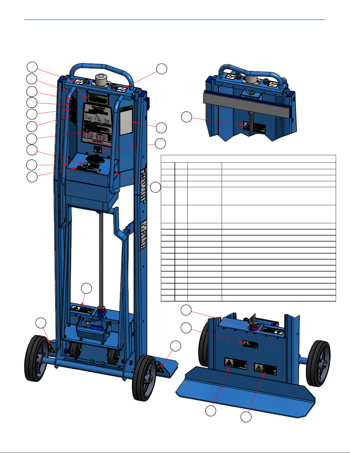
MANDATORY SAFETY LABEL PLACEMENT
Standard M-1/M-2B/M-2C PowerMate
NOTE: Model M-1 shown.
®
Units
11
10
12
4
1
9
8
2
3
6
on side.
13
14
5
7
18
ITEM
4
5
7
QTY
1
1
13
PART No.
051640/
052660/
051640
051650/
052650/
051650
PARTS LIST
DESCRIPTION
DECAL MS DISTRIBUTED BY LP051590C11
DECAL MS MAINTENANCE M-1/M-2B/M-2C052620/30/4012
DECAL LS CHARGER PLUG055820C13
DECAL MS LOAD DOWN M-1/
M-2B/
M-2C
DECAL MS LOAD UP M-1/
M-2B/
M-2C
DECAL - FAULT ALERTS057160A16
DECAL - SAFETY INSTRUCTION MS0572001
CAUTION DECAL - AUTHORIZED PERSONNEL057010A18
WARNING DECAL - MOVING PARTS Small057080A19
WARNING DECAL - KEEP OFF057050A110
DANGER DECAL - EXPLOSIVE ENVIRONMENT057040A111
DANGER DECAL - ELECTRICAL SHOCK057030A212
WARNING DECAL-ROTATING SHAFT/HAIR Large057110A213
DECAL - FUSE 10 AMPS057170A114
WARNING LABEL CRUSH FOOT PICTOGRAM057140A215
DANGER DECAL - CRUSH HAZARD FOOT057020A116
WARNING DECAL - PINCH POINT HAZARD057090A117
DECAL - CIRCUIT BREAKER PRESS OFF057150A118
15
13
12
15
16
17
2.02
PN 010030 Rev.E
Eng. 05/ 08/ 14
Page 8
PowerMate® Operation Manua
l
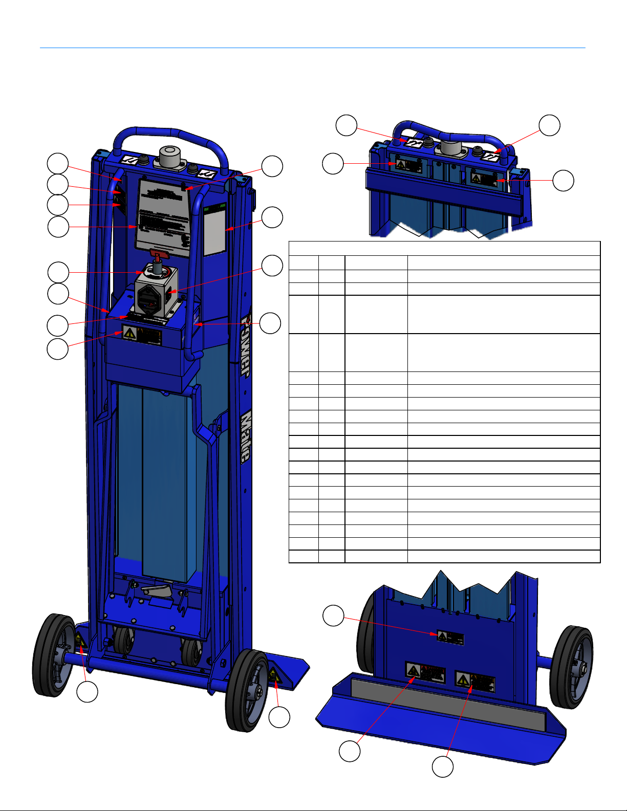
MANDATORY SAFETY LABEL PLACEMENT For
®
M-1/M-2B/M-2C PowerMate
NOTE: Model M-1 shown.
Units with Battery Switch
4 3
18
5
6
1
16
2
on box side
13
8
15
17
19
14
on box side
ITEM
4
10
QTY
13
1
PART No.
052620/30/4011
051640/
052660/
051640
051650/
052650/
051650
057040A15
057030A26
057020A17
057060A18
057070A19
057050A110
057090A111
057140A212
057160A113
057170A114
055860115
057180A116
057200117
9
PARTS LIST
DESCRIPTION
DECAL MS MAINTENANCE M-1/M-2B/M-2C
DECAL MS CHARGER PLUG05163012
DECAL MS LOAD DOWN M-1/
M-2B/
M-2C
DECAL MS LOAD UP M-1/
M-2B/
M-2C
DANGER LABEL EXPLOSIVE ENV.
DANGER DECAL - ELECTRICAL SHOCK
DANGER DECAL - CRUSH HAZARD FOOT
WARNING DECAL - MOVING PARTS Large
WARNING DECAL - SCREW GUARD
WARNING DECAL - KEEP OFF
WARNING LABEL PINCH POINT
WARNING LABEL CRUSH HAZARD
DECAL - FAULT ALERTS
DECAL - FUSE 10 AMPS
DECAL - CE MARK APPROVAL
DECAL - ROTARY SWITCH
DECAL - SAFETY INSTRUCTION MS
DECAL - DATE OF MANUFACTURE057210A118
DECAL - CIRCUIT BREAKER PRESS OFF057150A119
12
6
12
7
11
PN 010040 Rev.E
2.03
Eng. 05/ 08/ 14
Page 9

SAFETY PRECAUTIONS
l
READ THE MANUAL (Mandatory)
PowerMate® Operation Manua
Read all safety and operating instructions before anyone operates your
PowerMate
®
Unit. Use the PowerMate® unit only as described in this manual.
Retain all safety and operating instructions for future reference. Ensure they are
readily available.
Heed all warnings in the safety and operating instructions.
Follow all installation, operation, service, and safety instructions.
Operator must have received approved training on the PowerMate
®
unit to be
used. Training shall include theory, practice, and testing.
Never allow unqualified or un-authorized personnel to operate the equipment.
Operator must be familiar with normal operating practices and procedures.
Whenever there is and doubt as to safety, the operator should stop the operation
and not proceed until safe conditions are restored.
Operator is responsible for maintaining proficiency on PowerMate
®
equipment.
Familiarity with instructions, safety procedures, maintenance practices, controls,
operation, loading, are required at all times.
WARNING: Only trained personnel shall operate PowerMate
®
equipment. Failure
to comply may result in possible severe injury to the operator and/or others, and
damage and/or loss of property.
Wear safety shoes. Keep hair, loose clothing, fingers and all parts of the body
away from pinch points and moving/rotating parts. Use equipment handles and
controls for manoeuvring and operation.
Operator must have good hearing and vision (with or without correction) and
must have good depth perception.
Operator must not be afflicted with any health condition(s) that might cause loss
of control or ability.
Do not operate the equipment when using alcohol or taking medication that will
affect your physical performance or judgement.
Do not eat or drink during the operation of PowerMate
Stay alert when operating PowerMate
®
equipment.
®
equipment.
No horseplay or practical jokes when operating the equipment.
Do not lift people and never ride on the PowerMate
®
Unit.
Do not abuse the equipment. Use PowerMate
intended use.
®
equipment only for their
2.04
PN 010110 Rev.E
Eng. 05 / 08/ 14
Page 10

PowerMate® Operation Manua
l
SAFETY INSPECTION
WARNING: Do not use PowerMate® equipment if it is damaged. Check for corrosion.
Failure to do so may result in catastrophic failure, which may lead to injury, damage or
loss of property, and loss of life.
Inspect the PowerMate
operation can be safely completed. Insure all components of the unit are secure and
functioning.
Do not use accessories or attachments not recommended by the manufacturer, as this
may increase risk of damage and cause hazards.
Use only PowerMate
Attachment for box type loads, Cylinder attachment for cylindrical loads, etc.
Insure that the PowerMate
®
unit (see maintenance section) prior to using to ensure the
®
accessories best suited for the application ie: Strapbar
®
unit is charged and ready for the operation.
ENVIRONMENT SAFETY
CAUTION: Barriers, warning signs, designated walkways or other safeguards
must be provided where pedestrians are exposed to the risk of collision.
Plan your work. Make a plan of action from picking up the load to the point
where the load is delivered. Check for doorway size, pathway surfaces, ceiling
heights, tight corners, stair step size and integrity, turn radius considerations,
etc.. Always use the recommended number of operators for a load.
Check the work site. Inspect the area to be traversed with the PowerMate
Avoid debris, rough surfaces, pot holes, bumps, steep grades, etc. Avoid spills
of any kind, slippery surfaces, soft ground, and standing water. Observe any
condition that may cause loss of control of the PowerMate
®
unit leading to injury
and/or property damage.
Ensure planned route for PowerMate
®
operation is clear of obstacles and
uninvolved personnel. When visibility is obstructed use spotter person for
direction instruction and/or clear path of obstacles and un-involved personnel.
Do Not Place the PowerMate
must be capable of carrying the loaded PowerMate
®
Unit on an unstable surface. Supporting surface
®
Unit with Operator(s).
Check the condition of stairs and the edges of loading docks and vehicle beds.
When moving on or off a vehicle, be prepared for movement in the vehicle
suspension system.
Do not use PowerMate
®
equipment in an enclosed space where oxygen,
flammable, explosive or toxic vapours are present and/or are given off by oil
base paint, paint thinner, some mothproofing substances, or in an area where
flammable dust is present.
®
unit.
2.05
PN 010120 Re v.E
Eng. 12/ 18/ 12
Page 11

PowerMate® Operation Manua
l
LOADING SAFETY
CAUTION: Never lift a load that is over the rated capacity of the PowerMate® unit.
Estimate the weight and center of gravity position of the load and refer to the unit
Load Capacity Chart to ensure the load is within the loading envelope. The capacity
may be limited by the weight and strength of the operator(s). Do not operate with a
load that is beyond the operator's physical ability.
Do not attempt to increase the load capacity of the equipment by the use of chains,
rope, or other means of securing the equipment to the bed or bodies of vehicles,
handrails, wall brackets, etc..
Operators shall determine the balance of unfamiliar loads prior moving the load.
Work performed in a balanced condition is done easier and safer. New operators
should gain practice experience with lighter loads of approximately 250 lbs. with a
medium center of gravity before progressing to heavier loads. Do not raise or lower
the load too far past the balance point. Jog the equipment control switches so as
not to transfer the load weight too quickly. Training is mandatory!
Ensure the load is not damaged, properly packaged, no loose items such as tools
used in packaging the load and sharp items (such as nails) projecting from the
load.
Protect the PowerMate
failure. Always inspect straps prior to use. Insure the strapping latching mechanism
is fully engaged.
Verify load secureness at the beginning of use, and prior to climbing or descending
with the load. Check for any loose items or load shifting.
Never unstrap a load with the PowerMate
The unit will fall over backwards if the wheels are not in contact with a stable
surface when the unit is unloaded.
Do not load the PowerMate
side to side limits of the unit wheels.
®
strapping material from sharp edges to prevent strap
®
unit in an open (extended) condition.
®
unit with a load center of gravity that is outside the
SAFETY IN MOTION
CAUTION: When transiting a surface, avoid high speed turns that may cause
the load and PowerMate
to the PowerMate
®
unit to ensure the load cannot shift.
When transiting the unit without a load, ensure the load strapping devices are
secure, not dangling, to prevent a trip hazard and prevent entanglement in the
PowerMate
®
moving parts.
Always keep your attention in the direction you are moving, monitoring
clearances above, below, and each side of the PowerMate
visibility is obstructed use spotter person for directional instruction and/or clear
path of obstacles and un-involved personnel.
®
unit to tip. Remember that the load must be secure
®
and load. When
2.06
PN 010130 Rev.E
Eng. 05/ 08/ 14
Page 12

j
PowerMate® Operation Manua
l
SAFETY IN MOTION continued
Stay alert. Should something break, loosen, or malfunction, on your machine, stop
work and seek qualified assistance to correct the condition. When going down a
ramp or incline, always walk ahead of the machine and use the open/close controls
to engage the rubber guard (foot) with the ground to act as a brake. Do not allow
the loaded PowerMate® to attain an un-controllable speed. When moving a
PowerMate® unit down a stair without a load, always push the wheels off the step
before lowering the wheels to the next step.
Do not compress the top urethane bumper when the machine is under load.
BATTERY SAFETY
Lead-acid batteries contain hydrogen-oxygen gases that can be explosive and
sulphuric acid that can cause severe burns. To help avoid risk of danger and injury,
observe these precautions when handling or working with a lead-acid battery.
Wear ANSI approved safety glasses or goggles and a face shield. Wear proper
clothing to protect hands, and body. Wear appropriate rubber gloves and apron.
Never lean over a battery when testing or charging. Cigarettes, flames or sparks,
could cause a battery to explode. Keep all ignition sources away from battery. Do
not strike the sides of a battery with any spark producing item. Make sure work
area is well-ventilated.
Never touch both battery terminals with bare hands at the same time. Remove
rings, watches and dangling jewelry when working with batteries. The metal in the
ewelry can cause a shock and burns if contacted with the battery terminals.
Only use insulated/non-conducting tools when making connections on a battery.
Never lay tools or other parts on top of a battery.
Because the batteries used in L P International products are of the sealed type,
the battery should be replaced if there is evidence of spillage. If there is spilled
sulphuric acid present, neutralize with baking soda. Never remove vent caps on a
sealed battery. In the event of an accident, flush with water and call a physician
immediately. If venting gas is significantly inhaled, seek immediate medical
attention.
Never store batteries with explosives, flammable materials, chemicals, or food.
Protect batteries from crushing, punctures and shorting.
Do not charge or use booster cables or adjust battery connections without proper
instructions and training.
Keep batteries out of reach of children.
Do not accumulate used batteries. Dispose used batteries in accordance with
local environmental laws.
2.07
PN 010140 Rev.E
Eng. 05/ 08/ 14
Page 13

PowerMate® Operation Manua
l
CHARGING SAFETY INSTRUCTIONS
Battery Charger
Before using the battery charger, read all instructions and cautionary markings on the
battery charger, battery, and product using the battery.
DANGER: Electrical equipment may be hazardous if misused. Operation of this
product, and the device it is used on, must always be done with complete
knowledge of the product instructions and safety information. Failure to do so
may cause serious injury.
DANGER: RISK OF ELECTRICAL SHOCK, BURNS, OR FIRE -The battery charger
must be used as supplied. Do not use charger units if the input or output cord is cut
or frayed, or damaged in any way. Never replace, splice, or repair cables or
connectors supplied with the charger. Do not use the charger if case is damaged in
any way. Do not open the charger case for any reason. There are no user
serviceable parts. Always be sure that the charger is disconnected from the power
source and battery being charged before handling.
Your AC cord came equipped with a three-wire grounding plug (a plug that has a third
grounding pin). This plug will only fit only a grounded AC outlet. If you are unable to
insert the plug into an outlet because the outlet is not grounded contact a licensed
electrician to replace the outlet with a properly grounded outlet. Do not defeat the
purpose of the grounding plug. Pay particular attention to convenience of receptacles.
If an extension cord is necessary, use a cord with a current rating at least equal to that
of the charger. Cords rated for less amperage than the charger may overheat. Ensure
the pins of the extension cord plug are the same number, size, shape, as those on the
charger. Ensure the extension cord is wired properly and in good condition.
CAUTION: Position the charger and charger cords so that it is not tripped over, pulled,
or placed in contact with heated surfaces. Route charger cords so that they are not
likely to be walked on or pinched by items placed upon or against them. Protect the
charger from dampness or wet weather, such as rain, snow, and so on. Keep charger
away from sources of liquids, such as drinks, washbasins, bathtubs, shower stalls,
solvents, flowing water, and so on. Do not allow the charger, or any of its cords and
connectors lie in standing water such as a puddle.
CAUTION: Charge only properly maintained and rechargeable lead acid batteries of
the same voltage rating that is printed on the charger. Other battery types or voltages,
damaged batteries, or improperly maintained batteries may burst or emit dangerous
gases.
CAUTION: Only use the supplied charger on PowerMate
supplied by L P International are internally protected against battery polarity reversal
and overload. This limits potential damage to the charger. However, the charger does
not protect against shorting or overload of external wiring or of the battery being
charged. Integrity of the PowerMate
inspections.
®
unit wiring should be monitored during routine
®
products. The charger units
2.08
PN 010150 Rev.E
Eng. 05 / 08/ 14
Page 14
PowerMate® Operation Manua
l
CHARGING SAFETY INSTRUCTIONS continued
CAUTION: Do not operate the PowerMate® unit while connected to the charger.
Do not overload wall outlets or extension cords, as this can result in a risk of fire or
electrical shock.
Do not operate charger if it has received a sharp blow, been dropped, or otherwise
damaged in anyway.
To reduce risk of electrical shock, unplug the charger from the outlet before
attempting maintenance or cleaning.
Disconnect the power plug by pulling the plug, not the cord.
Do not handle the plug with wet hands.
Unplug the charger when not in use.
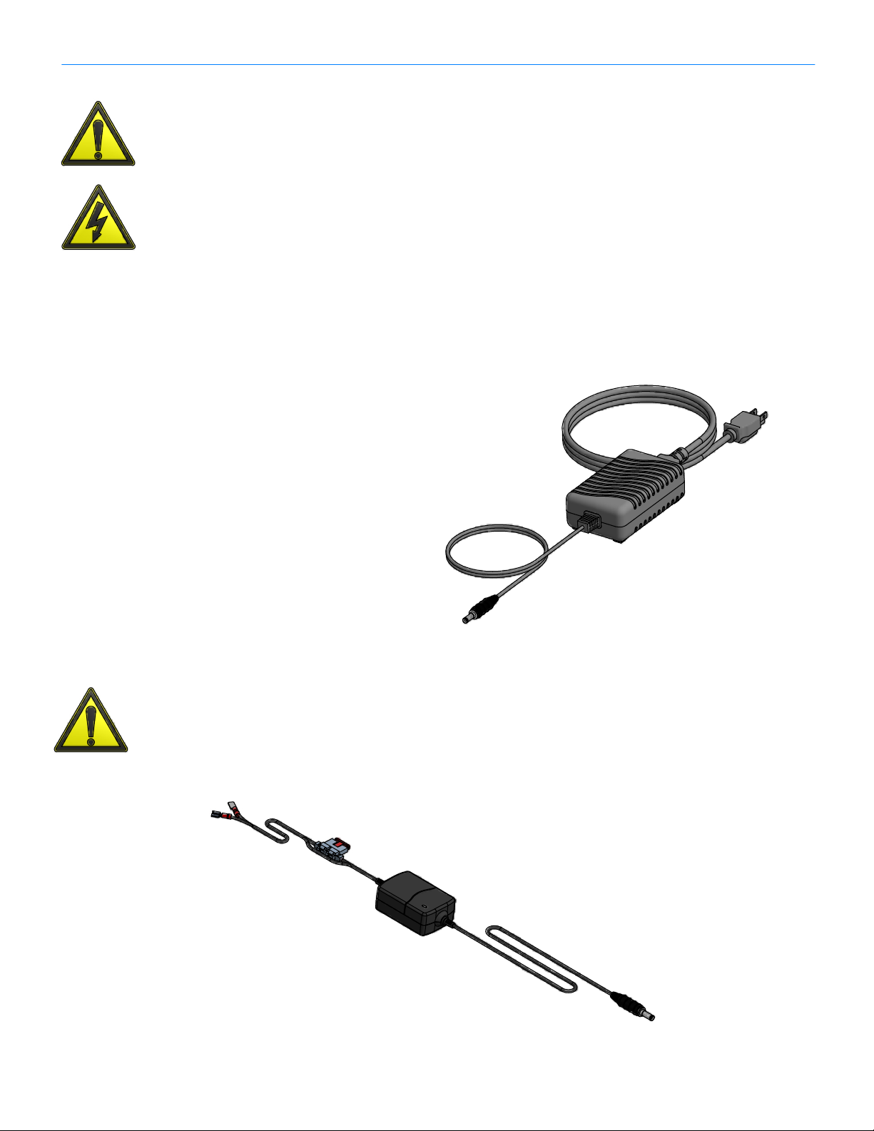
BATTERY CHARGER
PN 400211B
12V IN-VEHICLE CHARGER
WARNING: The In-vehicle charger cannot protect against vehicle damage caused
by faults in the wiring from the vehicle battery to the charger or faults in any other
portion of the vehicle wiring harness. The user must ensure that the wiring to the
charger adheres to the same vehicle wiring standards and safety precautions
required for all vehicle wiring.
IN-VEHICLE REMOTE
BATTERY CHARGER
PN 400218C
2.09
PN 010160 Rev .G
Eng. 04/ 18/ 18
Page 15
l
.
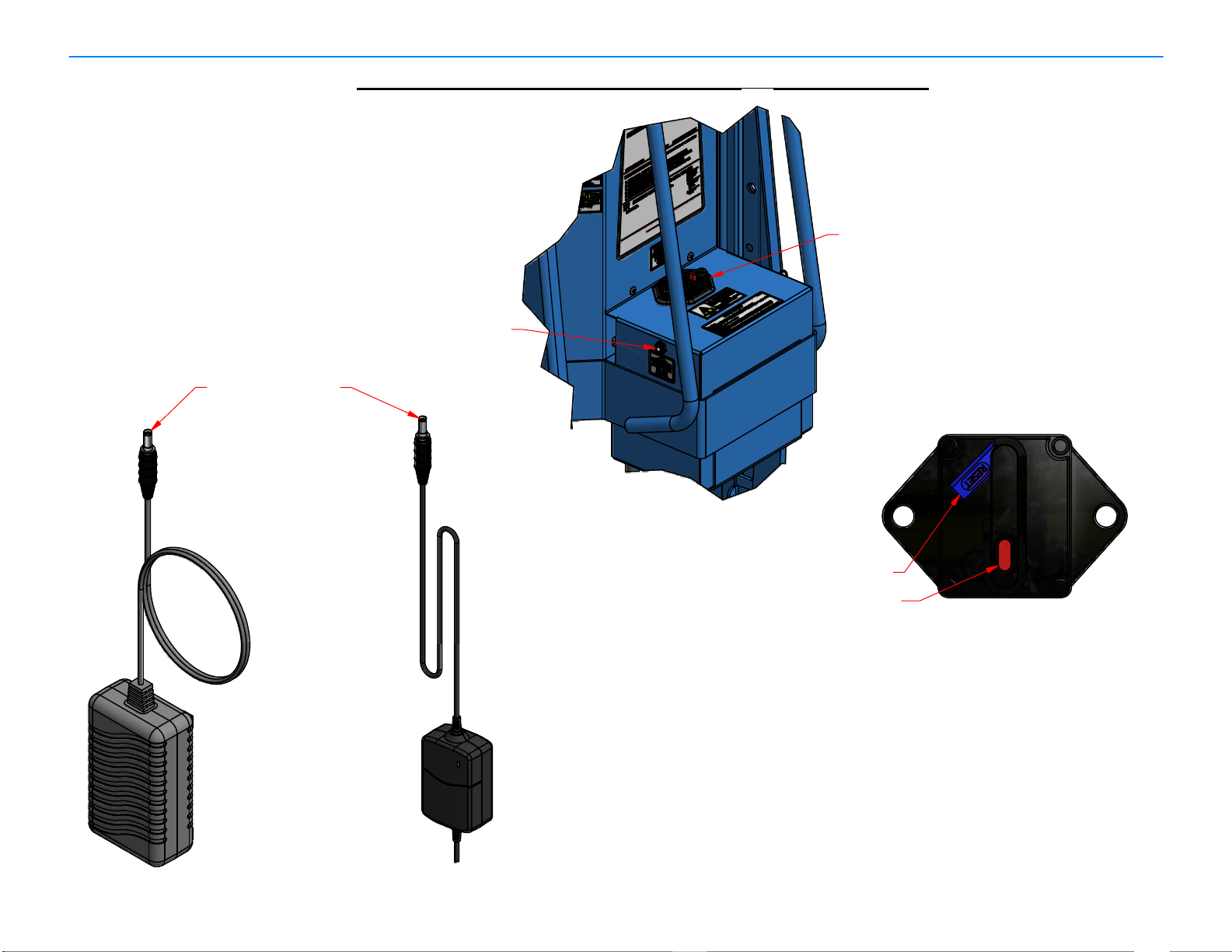
Charger Male Plug
PowerMate®Operation Manua
M-SERIES POWERMATE CHARGING INSTRUCTION
Circuit Breaker
Charging Receptacle
Breaker Reset Lever
(shown in off position)
Circuit Breaker Button
CIRCUIT BREAKER
INSTRUCTION:
1. Provide electrical power to the Battery Charger being used.
2. De-activate the PowerMate
Battery Box. The Breaker Reset Lever must pop out of the Breaker housing.
3. Insert the Charger Male Plug into the Charging Receptacle located in the Battery Box. The
charge cycle is fully automatic. The Wall Charger and the In-vehicle Electronic Charger
will indicate the charge status by LED indicators. Refer to the specific Charger documentation
4. To discontinue the charge cycle, dis-engage the Charger Male Plug from the Charging
Wall Charger
400211B
In-Vehicle
Electronic
Charger
400217C/8C
Receptacl e.
5. The PowerMate
®
can be re-activated for use by swinging the Circuit Breaker Reset Lever
back into the Circuit Breaker housing.
NOTE: The PowerMate
charged unit when called upon. In any case, the Circuit Breaker Reset Lever should always be
in the off (extended) position when the PowerMate
3.01
®
by depressing the Circuit Breaker Button located on top of the
®
can remain on the Battery Charger at all times, ensuring a fully
®
is not in use.
PN 010360 Rev.G
Eng. 04/ 18/ 18
Page 16

l
A
M-1
M-1 POWERMATE®LOADING INSTRUCTIONS
SAFE LOAD LIMITS
FOR ONE OPERATOR
450
400
(204)
(182)
350
450
(159)
(204)
250
400
(113)
(182)
STAIR
CLIMBING
SAFE LOAD LIMITS
FOR TWO OPERATORS
1000
800
(454)
(363)
800
1000
(363)
(454)
VEHICLE AND
DOCK LOADING
450
(204)
400
(182)
400
(182)
1000
(454)
850
(386)
300
(136)
350
(159)
250
(113)
600
(272)
800
(363)
PowerMate® Operation Manua
12
300
450
(204)
in.
mm
20
500
After establishing the weight of your load and its
center of gravity, refer to the load drawings to
12
300
500
(227)
determine:
650
(295)
450
(204)
20
500
1. That the capacity of the PowerMate is
400
650
(295)
FLAT SURFACE
MOVING
(182)
20
500
adequate for the intended application.
2. Whether one or two operators are
800
(363)
750
(340)
required.
1000
1500
(680)
(454)
SAFE LOADING RECOMMENDATIONS
IN LBS (KG).
M-2B
650
(295)
STAIR
CLIMBING
400
(182)
500
(227)
VEHICLE AND
DOCK LOADING
SAFE LOAD LIMITS
FOR ONE OPERATOR
400
500
(227)
500
350
(227)
(159)
450
(204)
STAIR
CLIMBING
(182)
300
(136)
450
(204)
400
(182)
400
(182)
VEHICLE AND
DOCK LOADING
SAFE LOAD LIMITS
FOR TWO OPERATORS
1000
800
(454)
(363)
1000
(454)
400
(182)
300
(136)
350
(159)
250
(113)
600
(272)
800
1000
(363)
(454)
FLAT SURFACE
MOVING
NOTE: LOAD RATINGS ARE CALCULATED FOR
TRAINED PROFICIENT, EXPERIENCED OPERATORS
ND SHOULD BE USED AS A GENERAL GUIDE ONLY.
M-2C
12
12
12
300
450
(204)
450
(204)
500
(227)
in.
mm
20
500
20
500
20
500
300
500
(227)
650
(295)
650
(295)
FLAT SURFACE
MOVING
SAFE LOAD LIMITS
FOR ONE OPERATOR
400
500
(182)
(227)
500
350
(227)
(159)
300
450
(136)
(204)
STAIR
CLIMBING
300
450
(136)
(204)
350
400
(159)
(182)
400
250
(182)
(113)
VEHICLE AND
DOCK LOADING
12
300
500
(227)
650
(295)
650
(295)
FLAT SURFACE
MOVING
SAFE LOAD LIMITS
800
750
(363)
(340)
FOR TWO OPERATORS
1000
700
(454)
(318)
1000
(454)
600
(272)
800
(363)
300
450
(204)
450
(204)
500
(227)
750
(340)
in.
mm
20
500
20
500
20
500
850
1000
(386)
(454)
750
450
(340)
(204)
STAIR
CLIMBING
850
800
(386)
(363)
500
400
(227)
(182)
VEHICLE AND
DOCK LOADING
1000
1500
(454)
(680)
1000
1250
(454)
(567)
FLAT SURFACE
MOVING
3.02
1000
(454)
750
(340)
STAIR
CLIMBING
850
(386)
450
(204)
800
850
(363)
(386)
500
400
(227)
(182)
VEHICLE AND
DOCK LOADING
1000
1500
(454)
(680)
1000
1250
(454)
(567)
FLAT SURFACE
MOVING
PN 010310 Rev.E
Eng. 05/ 08/ 14
Page 17

PowerMate® Operation Manua
l
POWERMATE® OPERATION
Loading on a Vehicle
1. Position the PowerMate
close to the tailgate or rear of the vehicle
allowing room for the wheels of the
®
PowerMate
to clear the vehicle when raising.
2. Push the "LOAD DOWN" button to raise the
wheels until they rest on the vehicle bed.
Lower the Hook Bar and engage the Hook
Attachment (when installed) on the vehicle
bed as shown in "B" and Detail "A1".
3. Push the "LOAD UP" button and raise the
toeplate/load to the vehicle floor as shown
"C".
4. Disengage the Hook Attachment by pulling the
®
PowerMate
away from the rear of the
vehicle. The PowerMate
positioned anywhere on the vehicle bed.
Unloading from a Vehicle
1. Lower the Hook Bar and connect to the Hook
Attachment in the vehicle bed by positioning
the PowerMate
"A1".
2. Push the "LOAD DOWN" button to lower the
PowerMate
as shown in "B".
3. Disengage the Hook Bar from the Hook
Attachment and stand the PowerMate
upright.
4. Push the "LOAD UP" button to lower the
wheels to the ground, whereupon the
PowerMate
5. If desired, the retractable dolly can be
®
as shown in "C" and Detail
®
toeplate and load to the ground
®
can be manoeuvred as required.
®
as shown in "A"
®
can now be
®
in
unclipped and used in connection with the
Hook Bar as shown in "D" to take the load and
assist handling for horizontal movement.
3.03
PN 010320 Rev.E
Eng. 05/ 08/ 14
Page 18

Upstai
PowerMate® Operation Manua
l
POWERMATE OPERATION
STAIR CLIMBING
1 Manoeuver the PowerMate
2 Pivot the PowerMate
rs
®
backwards to the first
step as shown in “A”, just near enough to allow the
wheels to clear the edge of the treads when raised
as shown in “B”.
as shown in “B”. Push the “LOAD DOWN” button to
raise the wheels to rest on step 2.
®
on the heel of the toe plate
3 Raise the toe plate off the ground, pivoting on the
wheels of the
button, raising the
resting the frame on step 1 as shown in “C”.
4 Pivot the PowerMate
that the wheels are clear of the steps and push
the “LOAD DOWN” button to raise the wheels
to step 3 as shown in “D”.
Repeat procedures 3 and 4 until the top of the stairs are
reached.
PowerMate
PowerMate
®
. Push the “LOAD UP”
®
frame and load and
®
on the load frame so
Down Stairs
1. Position the PowerMate® at the top of the stairs with
the load frame overhanging and clear of the steps.
Push the “LOAD DOWN” button to lower the load
and load frame, and rest it on step 2 as shown in
“E”.
2. Pivot the PowerMate
and push the “LOAD UP” button which will lower
the wheels to step 3 as shown in “F”.
3. Pivot the PowerMate
frame clear of the steps and push the “LOAD
DOWN” button to lower the load frame to rest on
the toe plate on step 1.
Repeat procedures 2 and 3 until reaching the
bottom of the stairs.
®
on the heel of the load frame
®
on its wheels to lift the load
3.04
PN 010340 Rev.E
Eng. 05/ 08/ 14
Page 19

PowerMate® Operation Manua
l
STORAGE PROCEDURE
If the equipment is not to be used for an extended period of time (over 3 months)
then the following storage procedure should be completed by a knowledgeable
service person.
1. Remove the front drive screw guard (if installed). Extend the main frames
fully. Clean and lubricate the drive screw with light machine oil. Replace
the drive screw guard.
2. Disable the equipment by placing the safety toggle switch in the “Off” (O)
position.
3. Store the equipment in a dry / dust-free location.
4. Check every 3 months that the battery is fully charged.
5. Before returning the equipment to service, it should be examined by a
trained and competent service person.
BATTERY CARE
The 12 volt DC battery system is maintenance free and sealed. The gelled
electrolyte inside the battery requires no maintenance whatsoever throughout its
life. DO NOT ATTEMPT TO OPEN THESE BATTERIES.
The best battery life and equipment performance will be attained by keeping the
battery fully charged.
The equipment has a small female battery charging receptacle located on the left
side of the battery box cover. This receptacle is connected directly to the battery.
The battery charger output wire has a mating male plug.
Insertion of the male plug into the female receptacle connects the battery charger
to the battery. Once connected the battery charger automatically commences
charging. The charger stops when the battery is fully charged.
3.05
PN 010650 Rev.E
Eng 05/ 08/ 14
Page 20

PowerMate® Operation Manua
l
Additional Tips for Operating the M-Series PowerMate
To enjoy "Trouble Free" PowerMate operations, remember the
following:
1. Keep the battery fully charged.
2. Follow the maintenance schedule and especially keep the screw clean and oiled with
light machine oil.
®
3. PowerMate
equipment is designed to take advantage of balance and leverage
principles. Work performed will be easier and safer when the load is maintained in a
balanced position. The operator should locate the center of gravity position of an
unfamiliar load prior to undertaking lifting or lowering operations.
4. New operators should be trained on light loads not exceeding 400 lbs. (182 kg),
progressing to heavier loads after gaining experience.
5. Never unstrap a load with the wheels up.
6. No not compress the top or bottom red bumpers on the drive screw when the unit has
a load.
7. Never lay the PowerMate® unit down on the battery box when transporting.
8. Ensure the overide bearing is properly adjusted on the drive screw.
9. Keep nuts and bolts tight on the dolly attachment and the hook bar.
®
10. Keep both hands on the handles when operating the PowerMate
.
11. When climbing stairs, keep the wheels at the back of the stair tread and the heel of the
machine back a safe distance from the step edge.
12. It is essential for reliability, and to conform with current Health and Safety legislation,
that your PowerMate
Agreement with L P International. Inc.
®
is maintained regularly. We recommend a bi-annual Service
3.06
PN 010370 Rev.E
Eng. 05/ 08/ 14
Page 21

l
10
PowerMate®Operation Manua
PARTS LIST
PART ITEM
1
2
STRAPBAR MS400080S
BATTERY 12V 32Ah SEALED051310C
DESCRIPTION
28
26
30
25
29
16
20
3
21
19
27
32
31
2
24
11
20
25
3
050860D4
5
052810
4002306
7
305770
3057718
3015229
05021010
05006012
05011014
10140015
10141016
05133017
30581018
10232021
05297022
30073323
30601024
05136426
05170527
052690B28
301393A29
05142530
05131131
05131232
SCREW ASSEMBLY M-1, M-2B300550C
ELECTRIC MOTOR
SOLID STATE CONTROLLER
RUBBER GUARD ASSEMBLY
MOTOR GUARD
SPLASH GUARD
BUZZER ASSEMBLY
SWITCH PUSH BUTTON 2 TERMINAL
AXLE30782011
WASHER 3/4 SAE
WHEE 8"30132013
COTTER PIN 1/8 x 1 ZINC
BOTTOM FELT
FELT TOP
WHEEL CASTER
DOLLY ATTACHMENT
INNER FRAME300010D19
OUTER FRAME300020C
TOP GUARD
STEEL ROLLER WHEEL
HOOK BAR
BATTERY COVER BOTTOM
BATTERY COVER TOP306000C
CIRCUIT BREAKER 100A
FUSE 10 AMP AGC
FUSE HOLDER
CHARGE PLUG
GASKET - CIRCUIT BREAKER
BATTERY TERMINAL COVER LH MS
BATTERY TERMINAL COVER RH MS
15
23
7
6
MODEL M-1
REPLACEMENT COMPONENT LIST
5
984
12 13 12 17 18
111422
PN 010500 Rev.E1
Eng. 03/ 31/ 16
Sheet 1 of 2
4.01
Page 22

®
l
Sheet 2 of 2
Eng. 03/ 31/ 16
PN 010500E1 EC
4.02
REPLACEMENT COMPONENT LIST
MODEL M-1 with BATTERY SWITCH
141514131621
1098
266
7
19
18
17
STRAPBAR M-SERIES400080A38
CHARGE PLUG ASSEMBLY MS301393A37
FUSE 10 AMP AGC05170536
FUSE HOLDER052690B35
GASKET - CIRCUIT BREAKER05142534
CIRCUIT BREAKER 100A05136433
SWITCH BATTERY DISCONNECT051362A32
SWITCH BOX MS30555031
BATTERY COVER BOTTOM30601030
BATTERY COVER TOP306005B29
BATTERY TERMINAL COVER RH05131228
BATTERY TERMINAL COVER LH05131127
ELECTRIC MOTOR050860D26
INNER FRAME300010D25
HOOK BAR
TOP GUARD
OUTER FRAME300020C
STEEL ROLLER WHEEL
FELT TOP
BOTTOM FELT
WHEEL CASTER 3" SWIVEL
DOLLY ATTACHMENT MS
COTTER PIN 1/8 x 1
WHEEL 8"30132015
WASHER 3/4 SAE
BOTTOM WHEEL AXLE M-1 PF
SWITCH PUSH BUTTON 2 TERMINAL
SCREW ASSEMBLY M-1, M-2B300550C
BUZZER ASSEMBLY
SOLID STATE CONTROLLER
SPLASH GUARD
BOTTOM RUBBER GUARD
MOTOR GUARD
BATTERY 12V 32Ah SEALED051310C
ROLLER GUARD
SCREW COVER
SCREW GUARD FRONT
SCREW GUARD BACK
DESCRIPTION
PARTS LIST
30073324
10232023
05297021
10141020
10140019
05133018
30581017
05011016
05006014
30782013
05021012
30152210
0528109
3057718
4002307
3057706
5
3026404
3026103
3025102
3025001
PART No.ITEM
22
11
24
30
5
27
37
29
33
34
3232
3135
36
28
12
3838
1
20
23
11
1
323
4
22
25
Operation Manua
PowerMate
Page 23

PowerMate®Operation Manua
l
24
2222
15
14
19
20
4 5
2
3 8
9918
25
1
20
10
7
6
30
28
29
27
31
33
32
23
26
17
21
16
13
111211
18
22
23
27
PART No.ITEM
3024701
2
050860D3
4002304
5
3057716
7
3015228
30782010
10196014
05133016
300110C
05297020
051310C
30300024
05170525
30601026
05142529
301393A31
05131233
PARTS LIST
DESCRIPTION
TOP GUARD
SCREW ASSEMBLY300550C
ELECTRIC MOTOR
BOTTOM RUBBER GUARD
MOTOR GUARD305770
SPLASH GUARD
SOLID STATE CONTROLLER052810
BUZZER ASSEMBLY
SWITCH PUSH BUTTON0502109
BOTTOM WHEEL AXLE
WASHER 3/4 SAE05006011
WHEEL 8"30132012
COTTER PIN05011013
FELT STRAP BAR
FELT TOP10141015
WHEEL CASTER 3"
DOLLY ATTACHMENT30581017
INNER FRAME
OUTER FRAME300120C19
STEEL ROLLER
HOOK BAR30073321
STRAPBAR ASSEMBLY400080S
BATTERY 12V 32Ah
OUTER FRAME STIFFENER
FUSE 10 AMP AGC
BATTERY COVER BOTTOM
BATTERY COVER TOP306000C
CIRCUIT BREAKER 100A05136428
GASKET - CIRCUIT BREAKER
FUSE HOLDER052690B30
CHARGE PLUG
TERMINAL COVER LH MS05131132
TERMINAL COVER RH MS
MODEL M-2B
REPLACEMENT COMPONENT LIST
4.03
PN 010510 Rev.E1
Eng. 03/ 31/ 16
Sheet 1 of 2
Page 24

®
l
Sheet 2 of 2
Eng. 03/ 31/ 16
PN 010510E1 EC
4.04
REPLACEMENT COMPONENT LIST
MODEL M-2B with BATTERY SWITCH
CHARGE PLUG301393A41
FUSE 10 AMP AGC05170540
FUSE HOLDER052690B39
GASKET05142538
CIRCUIT BREAKER 100A05136437
BATTERY DISCONNECT051362A36
SWITCH BOX30555035
BATTERY COVER BOTTOM30601034
BATTERY COVER TOP306005B33
TERMINAL COVER RH05131232
TERMINAL COVER LH05131131
STRAPBAR ASSEMBLY40008425
OUTER FRAME STIFFENER30300024
BATTERY 12V 32Ah SEALED051310C23
ROLLER GUARD MS PF30264030
SCREW COVER M-2B PF30262029
SWITCH GUARD M-2B PF30254028
SCREW GUARD M-2B PF30252027
SCREW GUARD BACK PF30250026
INNER FRAME
HOOK BAR30073320
STEEL ROLLER WHEEL05297019
OUTER FRAME300120C18
FELT TOP10141017
FELT STRAP BAR10196016
WHEEL CASTER 3"
DOLLY ATTACHMENT
COTTER PIN 1/8
WHEEL 8"30132012
WASHER 3/4 SAE
WHEEL AXLE30782010
SWITCH PUSH BUTTON
ELECTRIC MOTOR
MOTOR SUPPORT300800C
BUZZER ASSEMBLY
SOLID STATE CONTROLLER
SPLASH GUARD
BOTTOM RUBBER GUARD
TOP GUARD
SCREW ASSEMBLY300550C
MOTOR GUARD
DESCRIPTION
PARTS LIST
300110C21
05133015
30581014
05011013
05006011
0502109
050860D22
8
3015227
0528106
3057715
4002304
3024703
2
3057701
PART No.ITEM
13
15
20
34
23
31
32
41
33
37
38
10 11 12 11
8 19
14
36369921
39
40
5
3228 2929273018 26
6
7
22
1
4
16
24
2525
17
19
Operation Manua
PowerMate
Page 25

PowerMate®Operation Manua
l
2424
34
12
13
21
11
9
11
32
31
28
29
30
33
27
26
23
25
PART No.ITEM
0500603
0501105
3058106
0513307
1014109
300122B11
10103013
30577015
17
05281019
21
23
30601025
05131126
05131227
05136428
05142529
30
05170532
301393A33
30300034
14
PARTS LIST
DESCRIPTION
SWITCH PUSH BUTTON0502101
WHEEL AXLE3078202
WASHER 3/4 SAE
WHEEL 8"3013204
COTTER PIN
DOLLY ATTACHMENT
WHEEL CASTER 3"
FELT STRAP BAR1019608
FELT TOP
STEEL ROLLER WHEEL05297010
OUTER FRAME
INNER FRAME300112B12
TOP GUARD
HOOK BAR30073314
MOTOR GUARD
BOTTOM RUBBER GUARD40023016
MOTOR SUPPORT300800C
SPLASH GUARD30577118
SOLID STATE CONTROLLER
BUZZER ASSEMBLY30152220
SCREW ASSEMBLY300570C
ELECTRIC MOTOR050860D22
BATTERY 12V 32Ah SEALED051310C
STRAPBAR ASSEMBLY40008424
BATTERY COVER BOTTOM
TERMINAL COVER LH
TERMINAL COVER RH
CIRCUIT BREAKER 100A
GASKET - CIRCUIT BREAKER
BATTERY COVER TOP306000C
FUSE 10 AMP AGC
CHARGE PLUG
FUSE HOLDER052690B31
OUTER FRAME STIFFENER
7
8
221516
20
343510171819
MODEL M-2C
REPLACEMENT COMPONENT LIST
4.05
PN 010540 Rev.E1
Eng. 03/ 31/ 16
Sheet 1 of 2
Page 26

®
l
Sheet 2 of 2
Eng. 03/ 31/ 16
PN 010540E1 EC
4.06
REPLACEMENT COMPONENT LIST
MODEL M-2C with BATTERY SWITCH
343
ROLLER GUARD MS PF
SCREW COVER M-2C PF
SCREW GUARD FRONT M-2C PF
SCREW GUARD BACK PF
OUTER FRAME STIFFENER
STRAPBAR ASSEMBLY
BATTERY 12V 32Ah SEALED051310C
FUSE HOLDER
CHARGE PLUG ASSEMBLY
FUSE 10 AMP AGC
GASKET - CIRCUIT BREAKER
CIRCUIT BREAKER 100A
SWITCH BATTERY DISCONNECT
SWITCH BOX MS PF
BATTERY COVER BOTTOM
BATTERY COVER TOP
TERMINAL COVER RH
TERMINAL COVER LH
ELECTRIC MOTOR
SCREW ASSEMBLY M-2C300570C
BUZZER ASSEMBLY
SOLID STATE CONTROLLER
SPLASH GUARD MS PF
MOTOR SUPPORT300800C
BOTTOM RUBBER GUARD
MOTOR GUARD
HOOK BAR SUB-ASSEMBLY
TOP GUARD M-2C
INNER FRAME300112B12
OUTER FRAME
STEEL ROLLER WHEEL
FELT TOP
FELT STRAP BAR
WHEEL CASTER 3"
DOLLY ATTACHMENT
COTTER PIN
WHEEL 8"3013204
WASHER 3/4 SAE
WHEEL AXLE3078202
SWITCH PUSH BUTTON
DESCRIPTION
PARTS LIST
Operation Manua
30264040
30263039
30253038
30250037
30300036
40008435
052690B31
301393A33
05170532
05142530
05136429
051362A28
30555027
30601026
306005B25
05131224
05131123
050860D22
30152220
05281019
30577118
40023016
30577015
30073314
10103013
300122B11
05297010
1014109
1019608
051330
3058106
050110
0500603
0502101
PART No.ITEM
PowerMate
34
21
17
7
5
7
14
26
34
23
24
33
25
29
30
27
28
31
10181920221516
5
32
17
111213
37
21
38 39394040
8
36
3535
9
Page 27

PowerMate®Operation Manua
l
22 1 2 23 4
DETAIL B
A
Top Support on Inner Frame
7
8 9
8 10 2112
5
6
DETAIL A
(Assembly to Inner/Outer Frame)
18
19 20 14
11911 131413 23
12
21
7
DETAIL C
C
19
19
16
16
15
Concave this side
PART No.ITEM
1004501
0501403
0508005
0516807
0501209
05092011
05004013
10070014
05209015
050830B17
05185020
30084221
05064022
05061023
Ballnut Bracket on Outer Frame
B
17
PARTS LIST
DESCRIPTION
BRAKE CAP M-SERIES
WASHER THRUST BRONZE .0600508402
WASHER THRUST STEEL 1/2".090
WASHER RETAINER1509404
BRAKE SPRING
WASHER TOP BRAKE DRIVE0508206
ROLL PIN SPIROL 3/16"
WASHER THRUST STEEL 1/2"x .0300508108
THRUST WASHER
WASHER BOTTOM BRAKE DRIVE05085010
WASHER THRUST STEEL 1/2"x .060
BEARING RETAINER BAR30099012
PLATE WASHER 5/8"
URETHANE BUMPER
BALLNUT LOCKNUT 5/8 SCREW
SET SCREW 1/4-20NC x 5/1605055016
WASHER DISC SPRING 5/8"
BALLNUT 5/8"050170C18
DRIVE SCREW 5/8"102040C
WASHER 5/8"
COUPLING COVER WITH SPLINE
BOLT 1/4-20NC
LOCK NUT 1/4-20NC
SCREW ASSEMBLY M-1, M-2B
PN 300550
4.07
PN 010520 Rev.E
Eng. 05/ 08/ 14
Page 28

®
l
4.08
Eng. 05/ 08/ 14
PN 010530 Rev.E
PN 300570
SCREW ASSEMBLY M-2C
LOCK NUT 1/4-20NC
BOLT 1/4-20NC05064022
COUPLING COVER WITH SPLINE
WASHER 3/4"
DRIVE SCREW 3/4"102460E19
BALLNUT 3/4"
WASHER DISC SPRING 3/4"10283017
SET SCREW 1/4-20NC x 5/16
BALLNUT LOCKNUT 3/4 SCREW
URETHANE BUMPER 1/2 x 3/4
PLATE WASHER 1/2"
BEARING RETAINER BAR30099012
WASHER THRUST STEEL 1/2"x .060
WASHER BOTTOM BRAKE DRIVE05085010
BEARING THRUST STEEL
WASHER THRUST STEEL 1/2"x .030
ROLL PIN SPIROL 3/16"
WASHER TOP BRAKE DRIVE
BRAKE SPRING050800
WASHER RETAINER
WASHER THRUST STEEL 1/2".0900501403
WASHER THRUST BRONZE .060
BRAKE CAP M-SERIES
DESCRIPTION
PARTS LIST
05061023
30084221
05006020
05018018
05055016
05209115
10132014
05564013
05092011
0501209
0508108
0516807
0508206
5
1509404
0508402
1004501
PART No.ITEM
B
12
DETAIL A
2
11
7
(Assembly to Inner/Outer Frame)
210
DETAIL B
21
14
20
19
A
7
2013119
15
1918
17
Ballnut Bracket on Outer Frame
Operation Manua
PowerMate
1616
23
14
11
8 9 8
5
6
Top Support on Inner Frame
2
4
3
2
22 1
Page 29

PowerMate®Operation Manua
l
PARTS LIST
ITEM
6
2
6
10
3
9
5
4
5
6
7
1
4
QTY
4
PART No.
05012011
05014012
05080013
0508201
0508501
05092018
150940110
7
DESCRIPTION
BEARING THRUST STEEL
WASHER THRUST STEEL 1/2".090
BRAKE SPRING
WASHER THRUST STEEL 1/2"x .03005081024
WASHER TOP BRAKE DRIVE
WASHER THRUST BRONZE .060050840
WASHER BOTTOM BRAKE DRIVE
WASHER THRUST STEEL 1/2"x .060
ROLL PIN SPIROL 3/16"x 1 1/8"05168019
WASHER RETAINER
6
8
6
The Roll Pin can be found here
under the Brake Spring.
BRAKE ASSEMBLY KIT
(as it is packaged)
BRAKE ASSEMBLY KIT
PN 400150
4.09
PN 010590 Rev.E1
Eng. 03/ 09/ 16
Page 30

®
l
Eng. 03/ 09/ 16
PN 010600 Rev .E1
4.10
PN 400160
BEARING OVERRIDE KIT
(as it is packaged)
BEARING OVERRIDE KIT
4
2
4
1
5
3
URETHANE BUMPER 1/2"L x 5/8"ID1007001
WASHER THRUST STEEL 1/2"x .060
WASHER DISC SPRING 5/8"
BEARING THRUST STEEL
WASHER 5/8"PLATE ZINC
DESCRIPTION
PARTS LIST
Operation Manua
PowerMate
05092024
050830B13
05012012
05004021
PART No.
5
1
QTY
ITEM
Page 31

PARTS LIST
ITEM
5
1
3
5
6
4
QTY
PART No.
05006011
05012012
10283013
05092024
05564016
2
DESCRIPTION
WASHER 3/4 SAE
BEARING THRUST STEEL
WASHER DISC SPRING 3/4"
WASHER THRUST STEEL 1/2"x .060
URETHANE BUMPER 1/2 x 3/41013201
WASHER 1/2"PLATE 1 3/8"LS
4
M-2C BEARING OVERRIDE KIT
(as it is packaged)
M-2C BEARING OVERRIDE KIT
PN 400165
4.11
PN 010600 Rev.E1
Eng. 03/ 09/ 16
Page 32

PowerMate® Operation Manua
l
MAINTENANCE AFTER EVERY YEAR OF OPERATION
This equipment is designed for use as a heavy duty lifting device. To ensure operator safety and
continuing trouble free operation, have the equipment thoroughly checked by a trained and
competent service person at least once a year. This maintenance should be performed using the
following procedure.
1. Place a load of at least 500 pounds (230 kilograms) on the equipment. Cycle the equipment up
and down several times in order to evaluate its current condition. This load test will help reveal
the condition of the drive and brake systems, the frame structures and the electrical
components. Improper conditions may be exhibited by excessive vibration, unusual noise or
slow operation.
2. Check the inner and outer frame assemblies for bending, flattening, twisting, looseness or
worn surfaces of the frame members. Check the frame roller tracks for cracks and worn
surfaces.
3. Check the rollers for free rotation. Lubricate the roller axles with light machine oil.
4. Check that the two main frame wheels and main frame axle are in good condition. Lubricate
the two main frame wheels with multi-purpose grease.
5. Check that the strapbar mounting hardware is secure. Check that the load binding straps are
not cut or frayed and that the strap locking handles are secure.
6. Remove the drive screw as outlined under “Drive Screw Removal and Installation”. Clean the
drive screw and ballnut. Do not remove the ballnut from the drive screw.
7. Check for a close running fit between the drive screw and the ballnut. There should be no
wobble or excessive clearance and the ballnut should run smoothly and freely. There is a small
tube on the side of the ballnut for the re-circulation of the ball bearings. Check that the 2 tube
halves are fastened tightly together. Check that the area of the outside threads at the top of the
ballnut is in good condition. If any of these checks reveal a problem, replace the ballnut as
outlined in the manual.
8. If during the test of the equipment in step #1, there was excessive vibration, check the drive
screw for straightness. Replace the drive screw as outlined in the manual if the drive screw is
at all bent.
9. Check that the ballnut locknut, drive coupling, top and bottom red urethane bumpers and brake
cap are all in good condition.
10. Replace all of the components for the brake assembly and the override bearing as outlined
elsewhere in this manual.
11. Check that the electric motor armature, brushes and bearings are in good condition.
12. Reassemble the drivescrew assembly and electric motor in the equipment as outlined
elsewhere in this manual.
PN 010670 Rev.E
5.01
Eng. 05/ 08/ 14
Page 33

PowerMate® Operation Manua
l
MAINTENANCE AFTER EVERY YEAR OF OPERATION continued
13. Replace the Rubber End Cap on the bottom of the outer frame.
14. Remove and replace the two Push Buttons and Push Button Caps.
15. Check that all electrical wire connections are secure.
16. Check that the battery and battery charger are in good condition and that the
battery is fully charged.
17. Repeat the equipment load test from step #1. Cycle the equipment up and down
several times in order to evaluate its condition.
WARNING - All repairs, electrical or mechanical, should be carried out only by a
trained and competent service person. Use only approved repair
parts; any others may create a hazard.
5.02
PN 010680 Rev.E
Eng. 05/ 08/ 14
Page 34

PowerMate® Operation Manua
l
Procedure for Repairing the M-Series Drive Screw Assembly
NOTE: Read all instructions carefully before attempting to make repairs to any part of the drive screw assembly.
Assembly
1. Place machine on a suitable work bench, with the
machine resting on its wheels and rear handles
(toeplate up). Activate the unit until it is extended
approximately half-way. Disconnect the power supply
by way of the circuit breaker.
2. Refering to the Screw Assembly Drawings, remove
the two 1/4"bolts(22) and nuts(23). Proceed to
remove the brake cap (1), two bronze thrust washers
(2), steel washer(3), washer retainer(4), and brake
spring(5).
3. Drive out the 3/16"roll pin(7) taking care not to bend
the drive screw shaft. Place a suitable support
underneath the brake drive top washer(6)for this
operation.
4. Remove the brake drive top washer(6), two steel
thrust washers(8), thrust washer(9), brake drive
bottom washer(10), two bronze thrust washer(2) and
the steel thrust washer(11). NOTE: At this point, if it is
intended to replace the Bearing Overide or Ballnut,
complete those procedures first before continuing with
the brake reassembly.
5. As per the screw assembly drawing, replace the
brake assembly components (Brake Assembly Kit P/N
400150) in reverse as follows:
Items 2-11-2-10-8-9-8-6-7-5-4-2-3-2.
During assembly, place a few drops of light machine
oil on the thrust bearing(9) only. Remember to
support the brake drive top washer(6) when installing
the 3/16" roll pin(7).
6. Install the brake cap(1) and insert the 1/4"bolts(22)
and fasten with the nuts(23).
Installation of Override Bearing Kit,
Ballnut or Screw Removal
NOTE: For this procedure, it will be necessary to
remove all accessories like skid plate, extended
toeplate, screw guard, strapbars, etc.
1. Remove the brake assembly as outlined in the
Brake Assembly Procedure.
2. Remove the motor guard. Loosen (remove if
necessary) the two bolts holding the motor support
to the mounting bracket. Pull the motor away from
the screw assembly to disengage.
3. Loosen the set screws(16) in the ballnut
locknut(15). Unfasten the locknut from the
ballnut(18). The outer frame and inner frame are
now disengaged.
4. Move the drive screw(19) enough to allow removal of
the override bearing components. Remove the
bearing retainer bar(12), two steel thrust
washers(11), thrust washer(9), plate washers(13),
and the urethane bumper(14).
NOTE: At this point, if it is intended to replace the
Ballnut or removing the Drive Screw for service or
replacement, complete those procedures first before
continuing with the override bearing replacement.
5. As per the screw assembly drawing, replace the
override bearing components(Bearing Override Kit
PN 400160) in reverse order as follows:
Items: 13-14-13-11-9-11-12.
Apply a few drops of light machine oil to thrust
bearing(9) and the roller bearing in the bearing
retainer bar(12).
6. Guide the drive screw(19) back through the inner
frame top support and engage the spline coupling
(21) with the motor. Re-install the motor mounting
bolts but do not tighten. Reposition the outer frame
and/or ballnut so they engage through the ballnut
bracket leaving the unit extended approximately
halfway.
7. Thread the ballnut locknut(15) onto the ballnut(18),
but do not tighten.
8. Replace the brake assembly components as per the
Brake Assembly instruction step 5. Re-install the
brake cap(1) with 1/4"bolts and nuts(22/23) but do
not tighten.
9. Reactivate the electrical power through the circuit
breaker and operate the machine to full extension.
Push the motor/motor support towards the screw so
the skirt on the splined coupling(21) is 1/32" from the
motor. Tighten the motor mounting bolts.
10. Operate the unit to its fully retracted position. Tighten
the brake cap(1) bolts and nuts(22/23).
11. Tighten the ballnut locknut(15) to the ballnut(18),
hand tight only. Tighten the set screws(16).
NOTE: The ballnut must spin only when the unit is
run to its fully extended or retracted limits. If it does
not, adjust the tightness of the ballnut locknut.
12. Re-install the motor guard and strapbar(s). Re-attach
any removed accessories.
PN 010550 Rev.E
Eng. 05/ 06/ 14
5.03
Page 35

Eng. 05/ 08/ 14
PN 010580 Rev. E
5.04
9. Return to the instruction for the installation of the Drive Screw, step 4.
(Long turned end)
Drive Screw
8. Remove the plastic tape from the cross hole.
in position.
Band tape around the screw at both ends of the ballnut to keep the ballnut
to spin down the screw to approximately halfway along its length.
screw, over the tape and engage the drive screw thread. Allow the ballnut
turned end of the drive screw. Slide the ballnut off the arbor onto the
7. Place the end of the arbor firmly, centered and square, onto the long
disengage from the ballnut or all the balls in the ballnut will fall out.
the cardboard arbor with a side cutter. Be sure the arbor does not
on Screw Drive
over cross hole
Plastic Tape
6. To install a ballnut, the reverse happens. Remove the tie-wrap from
the ballnut and secure tight.
board arbor. Loop a tie-wrap through the Cardboard Arbor and around
that it is centered and square, and slide the ballnut up onto the card-
5. Place a cardboard arbor firmly against the end of the screw, insuring
Cardboard Arbor
from falling out into the cross hole.
thread. The tape over the cross hole prevents the balls in the ballnut
the ballnut up the screw until it is completely disengaged from the
4. Stand the drive screw vertically with the long turned end up. Thread
will be removed.
Ballnut
end of the screw over the cross hole. This is the end that the ballnut
3. Apply one layer of thin plastic tape banding around the long turned
in position, if installed.
2. Remove the tape from the drive screw that is keeping the ballnut
Follow the procedure for Drive Screw removal and replacement.
1. To begin, the screw assembly must be removed from the unit.
PROCEDURE:
BALLNUT REMOVAL AND REPLACEMENT
R
PowerMate Operation Manual
Page 36

PowerMate® Operation Manua
l
BOTTOM RUBBER GUARD REPLACEMENT
M-1, M-2B, or M-2C PowerMate
1/4-20NC Nut
Rubber End Cap
1/4"Plate Washer
Carriage Bolt 1/4-20NC x 3/4"
PROCEDURE:
1. Extend Outer Frame approximately 20", tipping the PowerMate back to rest on the
rear handles and wheels. Note: Unit shown vertically for visibilty only.
2. Remove the 1/4"Nuts with a 7/16"socket (preferably deep socket or with extension),
and ratchet wrench.
3. Remove the Carriage Bolts, Washers, and Rubber End Cap.
4. The replacement Rubber Guard comes with the components assembled finger tight.
Remove the 1/4"Nuts and place the Rubber End Cap on the bottom of the outer
frame, inserting the 1/4"Carriage Bolts in the holes in the outer frame.
5. Assemble the (6)1/4"Nuts to the 1/4"Carriage Bolts and tighten with the 7/16"wrench.
Replacement Kit No. 400230
5.05
PN 010620 Rev.E
Eng. 05/ 08/ 14
Page 37

l
A
PowerMate® Operation Manua
Remove Guarding if installed.
Push Button Caps
Push Button Switch
Slot Head Screws
DETAIL A
PROCEDURE:
1. Extend PowerMate Unit approximately 15". Rest unit on its rear handles an
w
heels. Activate Circuit Breaker to disconnect electrical curren
NO
TE: Remove screw guarding if installed -3 guards, 12 phillips head screw
Remove Push Button Cap(s) using water pump pliers
2.
3.
Slip Push Button Switch(es) out of mounting hole(s), wiring still connected.
.
t.
4. Remove two screws at the base of the switch(es) to disconnect the wiring.
5. Attach the wires to the replacement Push Button(s) using 1/4"slot screw driver.
6. Insert Push Button(s) into mounting hole(s)
Install Push Button Cap(s) and tighten using water pump pliers.
7.
8. Re-engage the Circuit Breaker.
.
Note: If screw guarding was installed, re-install prior to re-engaging the Circuit
Breaker.
d
.
PUSH BUTTON SWITCH REPLACEMENT M-SERIES
5.06
PN 010630 Rev.E1
Eng. 04/ 05/ 18
Page 38

PowerMate® Operation Manua
l
PARTS LIST
PART No.ITEM
3057501
1019602
3021103
3100404
5
0507706
7
310530
8
300500
300600
300490
05061010
3
1
4
5
6
77
2
STRAPBAR M-SERIES
FELT STRAP BAR 1/4"x 2"x 23"
CAM HANDLE
CAM
SET SCREW 5/16-18 x 5/16050990
BOLT 5/16-18 x 3/4"
LOCK NUT 5/16-18NC050620
STRAP 10' c/w TOGGLE
STRAP 12' c/w TOGGLE
STRAP 14' c/w TOGGLE
STRAP 16' c/w TOGGLE
PAN HEAD SCREW 1/4-20x3/40503009
LOCK NUT 1/4-20NC
REPLACEMENT STRAP/
TOGGLE KITS AVAILABLE
(Comes with fastener hardware):
DESCRIPTION
STRAP BAR ASSEMBLIES:
400080S - 10 ft. Strap
400082S - 12 ft. Strap
400084S - 14 ft. Strap
400086S - 16 ft. Strap
400310 - 10 ft. Strap
400320 - 12 ft. Strap
400300 - 14 ft. Strap
400340 - 16 ft. Strap
Washers in Kits
not required.
8
99 6
1010
STRAPBAR ASSEMBLY M-SERIES
Steel Strapbar
1/4"Locknut
Replacement Strap and Toggle
(2) 1/4-20NC X 3/4"
Pan Head Screw
1/4"Locknut
Head of screws must be oriented inwards.
This is done to prevent chaffing on strap.
REPLACEMENT STRAP INSTALLATION
TOOLS REQUIRED: 7/16"Wrench, 5/16"Flat Screw Driver.
5.07
PN 010640 Rev.E
Eng. 05/ 08/ 14
Page 39

PowerMate® Operation Manua
l
POWERMATE® M-SERIES WIRING DIAGRAM
White Wire
090710 for M-1
090720 for M-2
Fuse
Holder
PN 052690
Fuse 10A
PN 051705
Stair Climber
Load Up Push
Button Switch
PN 050210
301224
301410
Circuit
Breaker/
Power
Disconnect
PN 051364
301225
Battery
12V 32MAH
Sealed Dryfit
PN 051310
Stair Climber
Load Down
Push Button
Switch
PN 050210
301223
Fr
o
m
Fu
Charger
Plug
PN 050393
T
o
B
a
t
t
e
r
y
s
e
-
Grommet
301420
Splash
Guard
Controller
Unit
PN 052810
Buzzer PN 301522
301197
5.08
301198
Stair
Climber
Motor
PN 050860D
PN 010690 Rev.E1
Eng. 03/ 31/ 16
Sheet 1 of 2
Page 40

PowerMate® Operation Manua
l
POWERMATE® M-SERIES with BATTERY SWITCH
WIRING DIAGRAM
White Wire
090710 for M -1
090720 for M -2
Fuse
Holder
PN 052690
Fuse 10A
PN 051705
Stair Climber
Load Up Push
Button Switch
PN 050210
301224
Circuit
Breaker/
Power
Disconnect
PN 051364
Stair Climber
Load Down
Push Button
Switch
PN 050210
Battery
12V 32MAH
Sealed Dryfit
PN 051310
301225
301223
Fr
o
m
Fu
Charger
Plug
PN 050393
s
e
T
o
B
a
t
t
e
r
y
-
Battery
Disconnect
PN 051362
Grommet
301420
301410
Splash
Guard
Controller
Unit
PN 052810
Buzzer PN 301522
301197
301198
Stair
Climber
Motor
PN 050860D
5.09
PN 010690 EC Rev.E1
Eng. 03/ 31/ 16
Sheet 2 of 2
Page 41

®
11/ 16/ 15
PN010660B
5.10
M-SERIES POWERMATE SN 36000 and higher.
MOTOR REPLACEMENT INSTRUCTION for
Re-install the Motor Cover and fasten with the four 10-32NF Screws. Test and return to service.
10. Activate the electrical power at the Circuit Breaker. Close the unit and stand the unit up vertically.
Coupling/Motor Gap Detail
.060
Nuts ensuring Screw Assembly alignment.
Coupling and Motor as shown. Tighten the Bolts and
and Motor Support. Provide a .060"gap between the
8. Re-install the 1/4"Bolts and Nuts securing the Motor
7.Install the new motor engaging the Drive Screw Coupling.
connections as shown.
pair of Red Wires (PN301198) to the Motor post
6. Assemble the pair of Black Wires (PN301197) and the
PN050860D
MOTOR
NOTE: The Roller Axle has been removed for clarity.
INSTALL NEW MOTOR
position.
Diagram for proper installation
Refer to the Manual Electrical
Wires to the Controller.
9. Connect paired Black and Red
Axle (not shown), and remove the Motor.
Motor mounting lugs fork around the Roller
Coupling, rotating the Motor such that the
5. Dis-engage the Motor from the Drive Screw
Support. Remove the Motor Support.
4. Remove the 1/4"Bolts and Nuts retaining the Motor
3. Remove 1/4"Bolts and Nuts retaining the old Motor.
NOTE: The Roller Axle has been removed for clarity.
wires from the Controller.
2. Disconnect the Motor power
approximately 30 inches, and then remove the electrical power by way of the Circuit Breaker.
rest horizontally with the Motor and Controller facing up. Having the PowerMate on a work table in this position is helpful. Extend the PowerMate
1. Remove the four 10-32NF Screws securing the Motor Cover. Remove the Motor Cover to give access to the Motor. Tip the PowerMate back to
REMOVE OLD MOTOR
Operation Manual
PowerMate
Page 42

PowerMate® Operation Manua
l
M-SERIES SPECIFICATIONS ANSI/CSA
Model M-1 M-2B M-2C
Weight
Height
Width
Strapbar Width
Length
Ballscrew
Stroke Length
Extension Speed
5 /8 " 3 /4 "
4 0 " 4 8 "
165 lbs. 179 lbs. 182 lbs.
6 0 1 /2 " 6 7 1 /2 "
2 4 " 2 7 "
26 1/4"
17 1/8"
5" per sec. (no load)
Load Capacity
Stair Climbing
Dock/Vehicle Loading
Flat Surface Moving
1000 lbs.
1000 lbs.
1500 lbs.
M-SERIES SPECIFICATIONS CE
Model M-1 M-2B M-2C
Weight
Height
Width
Strapbar Width
Length
Ballscrew
Stroke Length
Extension Speed
15.88mm 19.05mm
1 .0 2 m 1 .2 2 m
75 kgs. 81 kgs. 82.5 kgs.
1 .5 4 m 1 .7 1 m
.61m .69m
.6 7 m
.4 4 m
127mm per sec. (no load)
Load Capacity
Stair Climbing
Dock/Vehicle Loading
Flat Surface Moving
NOTE: W eights are approxim ate due to m anufacturing tolerances. Data given for M -Series PowerMates
equipped with standard equipm ent.
454 kgs.
454 kgs.
680 kgs.
6.01
PN 010950 Rev.E
Eng. 05/ 08/ 14
Page 43

(
)
y
A
y
PowerMate® Operation Manua
l
STAIR CLIMBER SOLIDSTATE CONTROLLER
The Stair Climber Solid State Controller is a fully solid state Pulse Width Modulated (PWM) controller. Its
advanced microprocessor based control implements a state-of the-art power MOSFET motor drive. Advanced
features provide improved functionality, smoother operation, reduced mechanical stress, and protects against
abuse and system faults.
ADVANTAGES
- Reduced peak current reduces power loss in batteries, motor, and cabling.
- Reduced peak current reduces battery stress, increased service life.
- Reduced peak torque reduces mechanical stress, increasing service life of the gear train and motor.
- Smooth operation "feel" by controlled acceleration and deceleration (motor voltage ramp-up and
ramp-down) eliminating jerkiness.
- Automatically slows speed with heavy loads, improving control and safety.
- Overload protection shuts off if lift load is too heavy.
- Protects batteries by limiting minimum loaded voltage to 8.5 volts.
- Internal protections for many types of internal and external faults.
- Protects controller by inhibiting operation if battery voltage is to high.
- Detects battery+ or battery- short to frame and inhibits motor operation.
- Limits continuous operation to <30 seconds. Control wiring fault protection.
- Alerts to low or excess control heating (from over-use).
- Alerts to overload or excess continuous run time (control fault).
- Alerts to battery+ or battery- short to frame.
- Alerts to internal controller faults.
- Low standby power of less than 20mA.
SPECIFICATIONS
Operating Voltage Range: 8.5V - 14.4V
Maximum Voltage: 16.0V (non-operating)
Over-voltage shut-off 15.5V
Motor Current Limit: 100 Amps (+10%, -5%)
Output Time Rating (@100 Amps): 1.5Min. Minimum (ambient & initial temp<25ºC)
Continuous Current (Ambient<25ºC) 65 Amps (75 Amps in Le-Series Unit)
Maximum Run without stop: 25 to 30 Seconds
Input control current, Max.(@ 13V) 0.3 mA
Standb
Buzzer or LED output: 5 Volts, maximum 15mA
Standb
Operating Temperature Range: -25ºC to 50ºC
Storage Temperature Range: -40ºC to 85ºC
Environmental: Solid State Controller Unit is100% RoHS compliant.
FAULT ALERTS
Current (@12.6V) < 18m
Time (25% charge remains) 40 days (start with 20 AH battery, fully charged)
Faults are indicated by a buzzer producing a series of beeps to indictate various faults as follows:
One Beep - Overload condition (too much weight on Unit) - Reduce Load
- Maximum run time (25-30sec.) exceeded - Release and re-apply switch
Two Beeps - Low Battery - Recharge Battery
Three Beeps- Battery+ or Battery- shorted to frame. HALT USE AND RETURN FOR REPAIR
-System Fault - FAULTY UNIT -HALT USE AND RETURN FOR REPAIR
Four Beeps - Overheating due to excessive use (many minutes) - Allow five minutes to cool
6.02
sofware limited
PN 010710 Rev.E
Component 052810
Eng. 05/ 08/ 14
Page 44

PowerMate® Operation Manua
l
PowerMate® Battery Specifications
All PowerMate® M-Series units use the Pinnacle Battery produced by ABS Brand. The
Pinnacle Battery is the worlds first and best sealed, maintenance-free, gelled electrolyte
battery, providing dependable power, exceptional deep cycling capability and reliable
service. Features are:
100% gelled electrolyte. - Eliminates the need for fluid level checks.
Thick consistency of gelled electrolyte - Eliminates the damaging effects of severe
vibration.
Completely sealed, spill proof - Eliminates dangerous gasses and terminal
recombinant construction. corrosion (unless severely overcharged).
Compu-cast power-path and -For maximum durability, power and life.
computer controlled oxide.
Faster recharging. - Install it and forget it for quicker turnaround
time.
Extremely low self-discharge rate.
Runs considerably longer than comparable wet batteries.
Over 250 quality checks. - Guarantees highest quality , performance
and reliability.
SPECIFICATIONS: MODEL: 8GU1 12V 32Ah
Terminal: T874
CCA@0° F: 215A
Reserve Capacity @80°: 40
Approximate Weight: 24 lbs.(10.9 kgs.)
NOTE: Batteries used in PowerMate products are recyclable. Dispose of scrap
batteries according to the local environmental laws.
6.03
Ampere Hour Capacity
20 Hr. 6 Hr. 3 Hr. 1 Hr.
Rate Rate Rate Rate
31 26 24 20
PN 010700 Rev.E
Eng. 05/ 08/ 14
Page 45

A
BATTERY CHARGER REMOTE INSTALLATION INSTRUCTION
C
l
1/4"Male Disconnect
Positive Wire
PowerMate®Operation Manua
HARGER PN 400218C for Serial Numbers 36000 and higher.
7.5A Fuse
Two-sided Tape on back side.
1/4"Female Disconnect
Negative (Gnd.)Wire
Heat Shrink Tubing
for wire connections.
LED Indication: Charging = Red
Charged = Green
Locating the Charger:
Determine the position in the vehicle the PowerMate Unit will be using as it's charging station. The Battery Charger should be mounted in a
position that will allow visibility of the charger and give easy access for the charger output wire (4 1/2 feet) and charge plug to the PowerMate Unit.
The charger is equipped with adhesive backing for mounting to any flat surface.
NOTE:The mounting location should be free from moisture, dirt, and other contaminants. The charger should be mounted where the air is free to
move around it. It should never be located in a box, compartment, or covered by any object. Doing so may result in excess heating and reduced
performance. Do not expose the charger to any type of water spray. Do not immerse in water or any liquid. Should the charger become wet inside
it should be disconnected immediately and returned to the manufacturer for refurbishment. Mount where the charger and its cables will not be
physically damaged.
Input Wiring:
The installation will require a negative ground contact, and a positive wire coming from the vehicle battery. It is the installers responsibility to
ensure the wire is of proper size capable of carrying at least 7 Amps continuous. In order to ensure maximum performance of the charger, the
following wire sizes are recommended:
EXTENSION LENGTH MINIMUM WIRE GAUGE
Charge Plug to PowerMate
Units only.
Up to 10 feet 12 AWG
11 feet to 20 feet 10 AWG
21 feet to 30 feet 8 AWG
Over 30 feet Not recommended
ttach a 1/4"Male Terminal Disconnect to the negative (Gnd.) wire and a 1/4"Female Terminal Disconnect to the positive wire. Slip on a piece of
Heat Shrink Tubing (provided) over the lead in connections and connect the lead in wires to the mating charger input wires. Slide the Heat Shrink
Tubing over the connections and shrink. Secure all wires to prevent damage. Wire loom material may be used. It is the installer's responsibility to
ensure the wiring to the vehicle battery and negative ground point are properly protected and secure.
7.01
PN 010720 Rev.G
Assy. No. 400218C
Eng. 04/ 17/ 18
Page 46

®
l
®
Eng 05/ 09/ 14
Assembly 404300
PN 010730 Rev.E
7.02
Hook Bar.
Pin Supports to pass through the
on the machine axle tube allowing the
5. Raise the Bigwheel Attachment, rotating
over the machine axle tube.
4. Place Bigwheel Attachment Hook
A
pin rings towards eachother.
3. Retract Pins by pulling
position and engage latch.
2. Return Hook Bar to vertical
DETAIL A
installed) up out of the way.
1. Raise Dolly Attachment (if
M-Series POWERMATE
BigWheel Attachment
BIGWHEEL ATTACHMENT INSTALLATION
Operation Manua
PowerMate
6. Engage Pins by pushing Pins outwards.
POWERMATE
Page 47

POWERMATE®WHEEL BRAKE INSTALLATION
l
1. Extend machine approximately 24 inches.
Lean machine against a wall.
2. Raise Dolly Attachment (if
installed) up out of the way.
PowerMate®Operation Manua
Hook Bar
Axle Tube
Axle
3. Remove Cotter Pin
4. Remove Wheel and two Washers.
5. Remove 1/2"Nuts and Bolts.
LH Shoe Brake
LH Shoe Stop
Extended Nut
Typ.
Rubber
Typ.
RH Shoe Brake
6. Slide Shoe Stop onto Axle Tube
and re-install 1/2"Bolt and Nut.
Tighten assembly still allowing
Hook Bar to move with friction.
7. Align Wheel into Brake and slip
onto Axle (no washers). Extended
Nut faces inwards toward machine.
9. Apply a little grease to the Shoe
Stop Rubber to assist the Extended
Nut on the Shoe Brake to push on
and off easily.
10. Repeat all steps for opposite side.
7.03
8. Replace Cotter Pin.
PN 010740 Rev.E
Assy.No. 404100
Eng. 05/ 08/ 14
Page 48

®
l
Eng. 05/ 08/ 14
Assy.No. 400090
PN 010750 Rev.E
SECTION VIEW
7.04
Hook Box
A
Ref.
30 1/2"
29 1/4"
29 1/4"dimension is maintained. Reinforce the floor as required.
may also be installed in a side loading arrangement as long as the
NOTE: The Hook Box is installed in a Flatbed Vehicle in the same manner. It
POSITION IN PICK-UP TRUCK BOX
M-Series Hook Bar
Inside face of Hook
Hook Attachment
as required.
-reinforce underneath
Vehicle Floor
DETAIL A
when in the down position.
The Hook should be flush with the floor
Reinforce the floor underneath, if required.
2. Bolt or weld Hook Box to the vehicle floor.
cutout. Center the cutout in the vehicle floor.
(tailgate shown) 29 1/4"to the rear edge of the
Hook Box. Measure back from the drop edge
1. Cut a rectangular hole in the truck floor to suit the
PN 400090
HOOK BOX INSTALLATION
Operation Manua
PowerMate
Page 49

S
IDE HANDLE INSTALLATION INSTRUCTION
l
SIDE HANDLE KIT No. 400790
Side Handle
Typ.2
PowerMate®Operation Manua
2 1/8 in [54 mm]
3 3/4 in [95 mm]
Outer Frame
3/8 in [9.5mm] Drill
A
5/16"Split Lock Washer
Typ.2
Rear Face of
Outer Frame
5/16-18NC x 3/4"Bolt
Typ.2
DETAIL A
Instruction:
1. Drill a 3/8"diameter hole in the Outer Frame
3 3/4" above the top Strap Bar holes.
2. Insert 5/16"Bolt and Washer into 3/8"hole
from the inside of the Outer Frame. Thread
Side Handle onto Bolt. Align a flat side of
the Side Handle base to the rear face of the
Outer Frame. Tighten Bolt.
3. Repeat above for other Side Handle.
PN 010760 Rev.E
7.05
Assembly 400790
Eng. 05/ 08/ 14
Page 50

l
PowerMate
®
S
A
Fi
g
g
PowerMate® Operation Manua
ACCESSORIES/SPARE PARTS FOR M-SERIES MODEL
400100 EXTENDED TOEPLATE WIDTH
Depth 6 1/2" 16.51cm
Width 32" 81.28 cm
400090 HOOK BOX
Steel box with fold down brass
hook that mounts flush in the
bed of a truck or loading dock
to assist loadin
and unloading.
400180 EXTENDED TOEPLATE DEPTH 400061 CYLINDER ATTACHMENT
Depth 6" 15.24cm
Width 18" 45.72 cm
Height 4" 10.16cm
Depth
12" 30.48cm
Width
22" 55.88cm
400280 HORIZONTAL SUPPORT BRACKETS
400080S EXTRA STRAPBAR
400310 10' Strap 3.05m
400320 12' Strap 3.65m
400300 14' Strap 4.24m
400340 16' Strap 4.87m
400400 LOAD ELEVATOR
Two brackets per pkg.
Height 11" 27.94cm
Depth 14" 35.56cm
Width 16" 40.64 cm
Height 18" 45.72cm
Supports load at three
levels, centering the
weight over the axle,
permitting much easier
handlin
.
400200 FACE PLATE
ttaches to main frame to
cover front of machine.
L P INTERNATIONAL INC.
P.O. Box 696, 151 Savannah Oaks Dr.,
Brantford, ON N3T 5P9
TEL: (519)759-3292 FAX: (519) 759-3298
1-800-697-6283
www.powermate.info
Width
16" 40.64cm
Height
51" 129.54cm
400190 SKID PLATE
Width
19 1/2" 49.53cm
Height
47" 119.38cm
ts in front of strapbars.
Used to elevate loads for
easier handling.
8.01
PN 010920 Rev.E
Eng. 05/ 08/ 14
Page 51

PowerMate® Operation Manua
l
e
A
PowerMate® ACCESSORIES/SPARE PARTS FOR M-SERIES MODELS
404300 BIG WHEEL ATTACHMENT
BIG WHEEL mounts onto the frame of an M-1 or M-2B in
seconds. Designed to make traversing uneven, broken
terrain much easier.
051310 SEALED BATTERY 12V-30Ah
Gel pack, memory free battery.
Charge only with PowerMate
charger for best performance.
400217 IN-VEHICLE CHARGER
The MobileCharge 12E charges your PowerMate from the
vehicle 12V system. When the vehicle if off, it will continu
to charge for 2.5 hrs, protecting the vehicle battery. The 3stage charging profile extends battery life and is
independent of vehicle system voltage.
In-Vehicle Charger
comes with accessory
port plug. Battery
Charger Remote Kit not
shown.
400218 BATTERY CHARGER REMOTE KIT
Our hard-wired MobileCharge 12E smart
charging system keeps yout PowerMate
charged as it remains in the back of your
vehicle. It will never draw draw the
vehicle battery down below 70% capacity
so your vehicle will always will have
enough power to start the engine.
404210 STEP EXTENSION
410211 BATTERY CHARGER
Solidstate charger with automatic shut-off.
Safe to leave plugged into the PowerMate at
all times. Will not overcharge the battery.
400790 SIDE HANDLES
Comes with Mat Assembly and can be
placed at the top or bottom of a
staircase to create more room and a
better turning surface for maneuvering
your PowerMate with it's load. Allows
you to complete 17% more moves.
Step Extension = 20"x 28" Mat Assembly = 22"x 44"
304200 PIVOT PAD/MAT ASSEMBLY
vailable in two sizes, the Pivot Pad is
made of durable material which allows
you to turn the PowerMate, with it's
load, on a dime. Move your loads
effortlessly around tight corners while
protecting your customer's property.
Pivot Pad = 24" wide x 30"l ong x 1/4" thick
Mat Assembly = 28" wide x 44" long x 1/4" thick
L P INTERNATIONAL INC.
P.O. Box 696, 151 Savannah Oaks Dr.,
Brantford, ON N3T 5P9
TEL: (519)759-3292 FAX: (519) 759-3298
1-800-697-6283
www.powermate.info
8.02
PN 010930 Rev.G
Eng. 04/ 18/ 18
Page 52

PowerMat
e
®
A
Operation Manual
PowerMate® ACCESSORIES/SPARE PARTS FOR M-SERIES MODELS
400062 HOT WATER TANK ATTACHMENT
Designed to secure cylinder
loads to the machine minimizing
the risk of product damage.
404400 TWIN LIFT
llows for easy manoeuvering of large
loads such as vending machines in
tight spaces. Can turn machine and
load 360 degrees effortlessly.
404100 WHEEL BRAKES
Depth 3 1/4 inch 8.26cm
Width 5 1/4 inch 13.35cm
Height 6 1/2 inch 16.51cm
Weight: 12 1/2lbs. 5.67kg
406400 DOCKING STATION
The Docking Station is a secure
storage locker for storing and
charging a PowerMate. Hanging
devices are provided for
accessories.
400801 PREVENTATIVE MAINTENANCE KIT
Consistingof:
QTY PARTNo. DESCRIPTION
1 400230 BOTTOMRUBBERGUARDMS
2 050210 SWITCHPUSHBUTTON2TERMINAL
2 400310 STRAP10'c/wHARDWARE
1 400150 BRAKEASSEMBLYKIT
1 400160 BEARINGOVERRIDEKIT
L P INTERNATIONAL INC.
P.O. Box 696, 151 Savannah Oaks Dr.,
Brantford, ON N3T 5P9
TEL: (519)759-3292 FAX: (519) 759-3298
1-800-697-6283
www.powermate.info
8.03
PN 010940 Rev.E1
Eng. 08/ 14/ 14
Page 53

PowerMate® Operation Manual
Warranty
Every PowerMate® Safety Moving System supplied by L P INTERNATIONAL INC.
including accessories, with the exception of batteries, straps and shear pins is
guaranteed against faulty workmanship and defective materials for a period of one
year from date of purchase, when given normal use and maintenance in accordance
with operation manual.
The above warranty will apply only to the original purchaser.
L P INTERNATIONAL INC. do not hold themselves responsible for any damage
caused by atmospheric or chemical influences nor defects due to unskilled operation,
lack of maintenance and use of unprescribed lubricants. Neither do they accept
responsibility for normal wear and tear and consequences therefrom. Warranty
Service is available through your local authorized dealer or distributor. Warranty is
void if serviced by unauthorized persons.
Machine Model Serial No.
L P INTERNATIONAL INC.
P.O. BOX 696, 151 SAVANNAH OAKS DR. USA MAILING ADDRESS:
BRANTFORD, ONTARIO, CANADA P.O. BOX 1132
N3T 5P9 LEW ISTON, N.Y., 14092-8132
PHONE: (519) 759-3292
1-800-697-6283
FAX: (519) 759-3298
Manufactured By:
MAILING ADDRESS
8.04
PN 013010 Rev.E
Eng. 05/ 08/ 14
Page 54

DECLARATION OF CONFORMITY
ORIGINAL LANGUAGE VERSION
Date:
Manufacturer: L P INTERNATIONAL INC.
Box 696, 151 Savannah Oaks Dr
Brantford ON CA N3T 5P9
declares that the apparatus:
PowerMate Model Serial ¹
®
- conforms to the protection requirements of Council directive:
2006/42/EC (Machinery Directive)
2004/108/EC (Electromagnetic Compatibility Directive)
on the approximation of the laws of the Member States relating to machinery directive and
electromagnetic compatibility.
- STANDARDS including Annex 1 of 2006/42/EC and 4 (Lifting)
NAME L. Jeavons
TITLE General Manager
SIGNATURE
S01-007.01
Page 55

PowerMate® Operation Manua
l
DAILY MAINTENANCE SCHEDULE
NOTE: If attempting any service repair work disconnect the battery by
depressing the red button on the circuit breaker.
Inspect unit frame for structural damage.
Inspect for corrosion and broken welds.
Inspect wheels and tires. Grease the wheels if
required. Ensure the cotter pins are in place.
Inspect all bolts and fasteners are in place and
secure.
Inspect the strap(s) for damage. Nicks or tears are
not acceptable.
Inspect the push button switches for condition and
operation. Make sure the wiring is secure.
Test the circuit breaker for operation. Cycle the unit
testing for operation, direction and smoothness.
Observe the roller operation in the outer frame
rails. Oil rollers as required. Inspect the drive screw
and ballnut for damage, bending during operation,
and lubrication.
Ensure the operating manual is readily available
for reference.
Keep the battery fully charged.
FOR PARTS AND SERVICE CONTACT:
1-800-697-Mate
8.06
PN 010820 Rev .E
Eng. 05/ 08/ 14
 Loading...