

Powermate LiftGate LG-3, LiftGate LG-5, LiftGate Series, LiftGate LG-6 Installation & Operation Manual

T20-080.08
PN 018900 Rev.E1
PN 389570 Rev.E1
Eng. 06/ 01/ 17

PowerMate®LiftGate™ Installation & Operation Manual
TABLE OF CONTENTS
Section 1 - General
Warning Page………………………………………….
PowerMate LiftGate Description……………………..
Delivery and Warranty Registration………………….
Section 2 - Safety
Hazard Gr aphical Symbols………………………….. .
Li f tGate Mandatory Decal s…………………………...
Mandatory Safet y Decal Placement…………………
Safety Precautions…………………………………….
Section 3 - Instructions
Li f tGate Operating Instructi on………………………..
Loading Instruction for 250 Lb. LiftGate…………….
Loading Instruction for 500 Lb. LiftGate…………….
Installation Dimensional Requirements……………..
Installation Kit………………………………………….
Addi tional It ems and Tools……………………………
Determining Installation Location…………………….
Base Hole Locat i ons…………………………………..
Installing the LiftGate Unit…………………………….
Running the Wires……………………………………..
Section 4 - LG-Series PowerMate Components
Replacement Component Drawing………………….
Replacement Component List………………………..
Section 5 - Maintenance
Maintaining The PowerMate LiftGate………………..
Actuator Removal/Installation Instruction…………...
Actuator Removal/Installation Instruction Drawing...
Limit Switch Assembly/Adjustment Instruction……..
Limit Switch Assembly/Adjustment Drawing………..
Roller Repl acement……………………………………
Lefthand Strapbar Assembly…………………………
Righthand Str apbar Assembly……………………….
LG-Series Wi ring Di agram……………………………
Actuator Manual Retraction…………………………..
Section 6 - Specifications
PowerMate LiftGate Specifications………………….
Section 7 - Accessory Installations
Cradle Attachment I nst allation……………………….
Section 8 - Accessories
LG-3 Li f t Gate Features………………………………. .
LG-6 Li f t Gate Features………………………………. .
Warranty………………………………………………..
Decl aration of Conformity…………………………….
Daily Maint enance Schedule…………………………
1.01
1.02
1.02
2.01
2.02
2.04
2.05
3.01
3.02
3.03
3.04
3.05
3.06
3.07
3.08
3.09
3.10
4.01
4.02
5.01
5.02
5.03
5.04
5.05
5.06
5.07
5.08
5.09
5.10
6.01
7.01
8.01
8.02
8.03
8.04
8.05
PN 018020 Rev. E
i
Eng. 11/ 10/ 15

W
PowerMate®LiftGate™ Installation & Operation Manual
ARNING
Failure to obey the Instructions and Safety
rules in this manual could result in death or
serious injury.
Read the Operating Manual completely.
Only competent, trained operators may use
this equipment.
Training is essential to understanding all the
features and capabilities of your PowerMate,
and ensure good safe work practices.
Training courses are available through
L P INTERNATIONAL INC., please call
1-800-697-6283
ATTENTION!
The photographs, diagrams and illustrations in his
manual are of the LG-6 Right-hand unit installation in
a box truck. Use this manual as a guideline when
installing Left-hand units and/or other LG-Series units
in alternative locations in other vehicle types.
1.01
PN 018100 Rev.D2
Eng. 01/ 10/ 13

PowerMate®LiftGate™ Installation & Operation Manual
PowerMate® LiftGate™
In choosing to buy a PowerMate®, you will find that it will help your business in more
ways than you can imagine. Not only is it a revenue generator, PowerMate
®
is also a
labour saver and a great promotional tool to help you expand your business in the
commercial and industrial markets.
®
The PowerMate
LiftGate™ provides a safe and easy way for moving and delivering
heavy and awkward loads in and out of your vehicle at the push of a button.
We at L P INTERNATIONAL INC. look forward to continuing our mission to help you
realize your full profit potential of having a PowerMate
®
LiftGate™ in your Profit
Center.
For more information on the complete PowerMate
1-800-697-6283.
DELIVERY AND WARRANTY REGISTRATION
®
product line, please call toll free
Upon receipt of your LiftGate™ unit, examine the unit to determine if it has been
damaged in transit. Examine the unit for mishandling, paying particular attention to
the control box and switches, the limit switch assembly and the exposed wire
looms.
If required, make note of any deficiencies on the Delivery Acceptance Form.
Registering your unit for the Warranty can be done online at www.powermate.info.
Click on Service, fill in the required fields under Warranty and click Send Now.
When ordering parts, or requesting information or service on the unit, please refer
to the model and serial number. The model number can be found on the data
decal on the top of the control box. The serial number can be found stamped to
the top corner of the aluminum outer frame.
WARNING The use of this equipment with any options other than
those specified in this manual may create a hazard.
Manufactured By:
L P INTERNATIONAL INC.
P.O. Box 696, 151 Savannah Oaks Drive
Brantford, Ontario, Canada N3T 5P9
TEL: (519) 759-3292 FAX: (519) 759-3298
1-800-697-6283
1.02
PN 018910
Rev.D2
Eng. 01/ 10/ 13

PowerMate®LiftGate™ Installation & Operation Manual
HAZARD GRAPHICAL SYMBOLS
The PowerMate® products use graphical symbols, safety colours, and signal words
throughout the Operators Manual and on the units themselves. Operators using the
PowerMate
®
must familiarize themselves with these symbols.
Safety Alert Symbol: This symbol indicates a potential personal
injury hazard. Safety information following
this symbol must be followed to avoid
possible injury or death.
DANGER: Indicates an imminently hazardous situation
which, if not avoided, will result in death or
serious injury.
WARNING: Indicates a potentially hazardous situation
which, if not avoided, could result in death
or serious injury.
CAUTION: Indicates a potentially hazardous situation
which, if not avoided, may result in minor
or moderate injury.
NOTICE: The signal word to address practices not
related to personal injury.
SAFETY LABEL MAINTENANCE
Safety of the operator and surrounding environment must be considered at all times.
®
To that end, safety labelling on the PowerMate
must be maintained to provide legible
safety information. Clean the labels with soap and water. Do not use solvent-based
cleaners because they may damage the labels. Replace damaged or missing labels.
Replacement labels may be purchased from L P International Inc. Customer Service
Phone number 1-800-697-Mate.
2.01
PN 018090 Rev.D2
Eng. 01/ 10/ 13
PowerMate®LiftGate™ Installation & Operation Manual
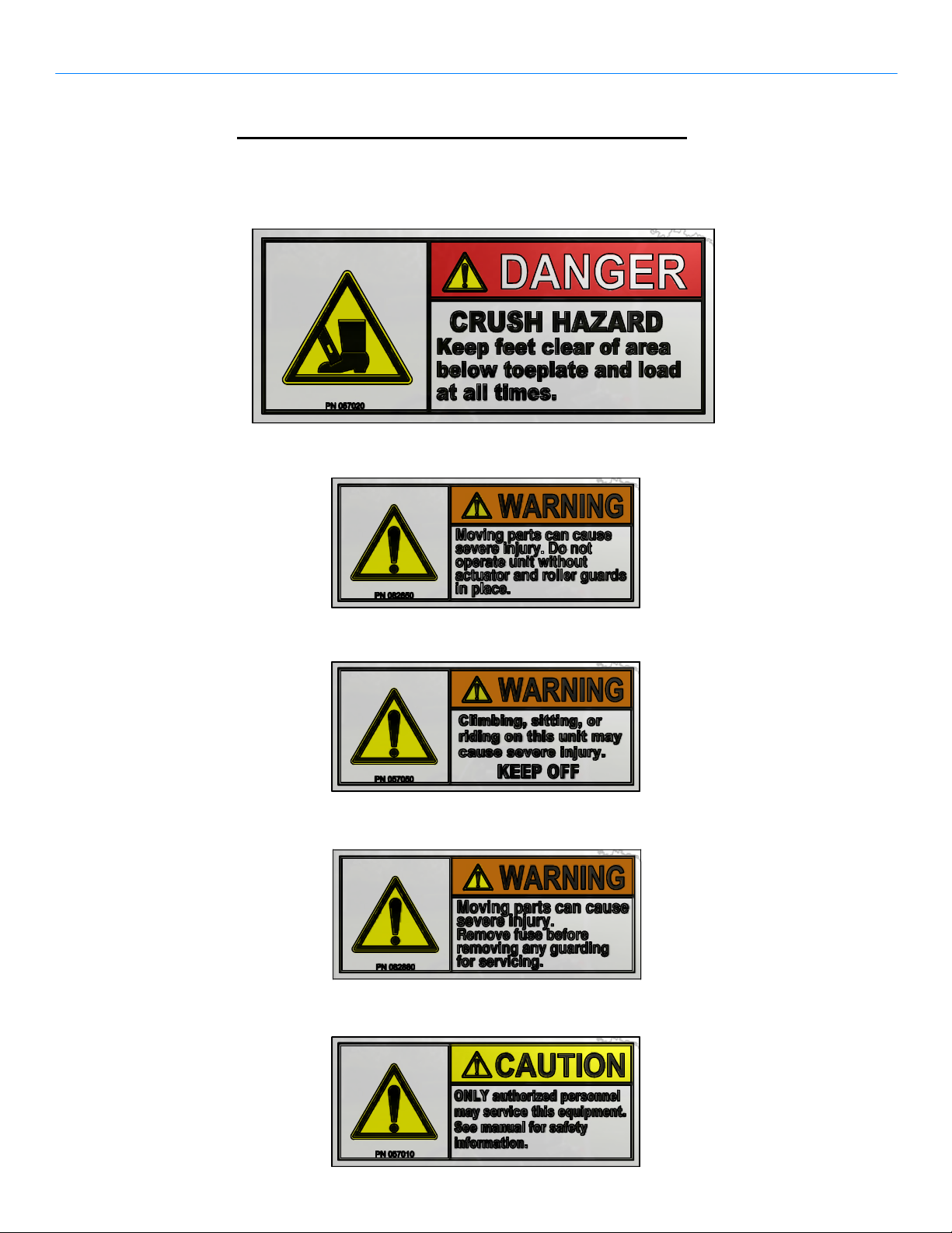
DANGERS, WARNINGS, AND CAUTIONS
The following decals are mandatory. Refer to the Location of Mandatory Labels Drawing
for placement. Replacement decals are available from LP International Inc.
PN 057020 - 1 Required
PN 082650 - 1 Required
PN 057050 - 1 Required
PN 082880 - 1 Required
PN 057010 - 1 Required
2.02
PN 018040 Rev.D2
Sheet 1 of 2
Eng. 01 / 10/ 13
PowerMate®LiftGate™ Installation & Operation Manual
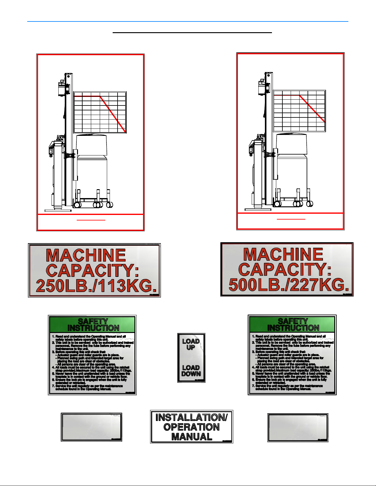
A
DDITIONAL MANDATORY DECALS
The following decals are mandatory. Refer to the Location of Mandatory Labels Drawing
for placement. Replacement decals are available from LP International Inc.
LIFT GATE 250Lb.(113Kg.) SERIES
POWERMATE
E
C
A
F
E
T
A
L
P
E
LOAD CENTER OF GRAVITY
O
T
250(113)Max.
4"
16"
8"
12"
24"
18"
250(113)
230(104)
210(95)
190(86)
170(77)
LOAD
lbs.(kgs.)
LIFT GATE 500Lb.(227Kg.) SERIES
POWERMATE
E
C
A
F
E
T
A
L
P
E
LOAD CENTER OF GRAVITY
O
T
4"
500(227)Max.
16"
8"
12"
24"
18"
500(227)
400(181)
300(136)
200(91)
100(45)
LOAD
lbs.(kgs.)
LOAD MUST BE SECURED TO THE UNIT WITH
THE RATCHET STRAP PROVIDED.
WARNING
PN 082600
PN 082860 - 2 Required
PN 082830
LOAD MUST BE SECURED TO THE UNIT WITH
THE RATCHET STRAP PROVIDED.
WARNING
PN 083600
PN 083860 - 2 Required
PN 082610
POWERMATE LIFT GATE SERIES
Model No. LG−"X"
Load Capacity: 250lbs./113kgs.
Unit Useable Stroke: 40in./1.02m
Unit Weight: 230 lbs./104kgs.
Voltage: 12vdc Amperage: 30A Max.
Made in CANADA
PN 08262X
Note: "X" will be Unit Size
"3" - LG-3 Unit
"6" - LG-6 Unit
PN 082630
2.03
PN 083610
POWERMATE LIFT GATE SER IES
Model No. LG−"X"
Load Capacity: 500lbs./227kgs.
Unit Useable Stroke: 40in./1.02m
Unit Weight: 230 lbs./104kgs.
Voltage: 12vdc Amperage: 30A Max.
Made in CANADA
PN 08362X
Note: "X" will be Unit Size
"3" - LG-3 Unit
"6" - LG-6 Unit
PN 018040 Rev.D2
Sheet 2 of 2
Eng.01/ 10/ 13

®
Eng. 01/ 10/ 13
PN 018030 Rev.D2
available from L P International Inc.
that these decals are in place. Replacements are
potential safety hazards and operational limits. Insure
operators, owners, and maintenance personnel, of the
2.04
500Lb. LIFTGATE UNITS
LABELS FOR 250Lb. AND
LOCATION OF MANDATORY
NOTE: Indicated Decals are intended to create awareness in
5
1
10
4
DECAL - LOAD UP/DOWN LG-SERIES
DECAL - INSTALLATION/OPERATING MANUAL082630110
be Unit Size
6
8
2
Note: "X" will
DESCRIPTIONPART No.QTYITEM
LiftGate™ Installation & Operation Manual
PowerMate
DECAL - LG SPECIFICATIONS 500Lb.
DECAL - LG SPECIFICATIONS 250Lb.
DECAL - LOADING CHART 500Lb. SERIES
DECAL - LOADING CHART 250Lb. SERIES
DECAL - SAFETY INSTRUCTION 500Lb.
DECAL - SAFETY INSTRUCTION 250Lb.
DECAL - LOAD CAPACITY 500Lb.
DECAL - LOAD CAPACITY 250Lb.
DECAL - WARNING AUTHORIZED PERSONNEL0570101
WARNING DECAL - KEEP OFF
DECAL - WARNING MOVING PARTS FUSE08288013
DECAL - MOVING PARTS
DANGER DECAL - CRUSH HAZARD FOOT05702011
PARTS LIST
082830111
08362X
08262X
19
083600
082600
18
083610
082610
1
7
083860
082860
26
5
05705014
08265012
11
9
3
7
6

PowerMate®LiftGate™ Installation & Operation Manual
Y
SAFETY PRECAUTIONS
WARNING: Read and understand all instructions. Follow the safety rules listed below
as well as the other basic safety precautions. Failure to do so may result
in serious injury.
WORK AREA
CHECK YOUR WORK AREA. Inspect your work are for obstacles such as holes,
debris or rough spots. Look for areas not able to support the load, such as access
or drain covers or soft ground. Watch out for liquid spills or slippery surfaces. Be
on the alert for anything that might cause you to lose your balance, control or
concentration. Insure that the vehicle is level. The LiftGate™ unit should not be
activated if the vehicle is on any inclination.
PLAN YOUR WORK. Arrange your work to avoid unnecessary steps or effort.
Position your vehicle for proper clearance from roadside curbs and obstacles.
Insure that the Load Chart is considered when engaging the load to be
transferred. Do not overload the PowerMate.
KEEP YOUR WORK AREA CLEAR. All visitors should be kept away from the
work area.
PERSONAL SAFET
STAY ALERT. Always focus your attention in the direction of travel. Always maintain
proper footing and balance. Constantly check for clearance above, below and on all
sides. When loading onto or off of a vehicle, be prepared for movement in the
vehicle suspension system.
USE COMMON SENSE. Do not operate equipment when you are tired or injured.
Keep both hands positioned on unit at all times. Never play games. Do not ride on
the unit. Do not attempt to use the equipment as a jack.
MAINTAIN THE EQUIPMENT REGULARLY
DO NOT operate equipment that is known to be damaged or malfunctioning. Never
remove or override any mechanical or electrical safety devices. Poorly maintained
equipment jeopardizes the safety of the operator and all other personnel. Remember
safety is your responsibility. Complete a daily inspection procedure. Have the
equipment thoroughly checked by a competent service person at least once a year.
SECURE FOR TRANSPORT
When the equipment is not in use, ensure the LiftGate™ and the load are fully secure
before moving the vehicle.
2.05
PN 018110 Rev.D2
Eng. 01/ 10/ 13
PowerMate®LiftGate™ Installation & Operation Manual
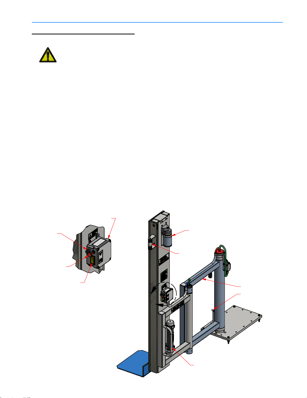
OPERATING INSTRUCTIONS
WARNING! The vehicle must be parked on a level surface prior to operating the
LiftGate Unit. Safety shoes must be worn! Read the instructions completely
before operating the unit. DO NOT exceed Max. Capacity Limit.
1. Refer to the Loading Chart, in this Manual or on the face of the LiftGate Unit, to
determine if the load to be lifted will fit in the load capacity envelope of the Unit.
2. The Rocker Switch controls the up/down operation of the unit. Depressing the
top of the switch will raise the toeplate and depressing the bottom of the switch
will lower the toeplate. Raise the toeplate off the surface and dis-engage the
Lock Pin, to allow positioning of the Unit. Manuever the toeplate to the load and
lower the toeplate to the surface. Place load on the toeplate and secure the
load to the Unit using the strap provided.
3. Raise the load to the desired height. The actuator will make a ratcheting sound
when the top stroke limit is reached.
4. Swing the load to required position using the Unit Handles. Use the Lock Pin
whenever possible.
5. Lower the load down to the desired surface(vehicle floor or the ground). The
down stroke will end automaticly when the toeplate makes contact with any
surface. Remove the load.
6. When the operation is complete, park the Unit folded in the vehicle. Engage the
lock pin, lower the toeplate to the floor until the actuator stops(automatic), and
depress the Emergency Stop/Battery Disconnect Switch.
Fuse Holder
with 30A Fuse
Emergency Stop/
Battery Disconnect
Switch
Rocker Switch
Control Box
DETAIL A
Actuator
Top Handle
Main Swing Arm
Lock Pin
A
3.01
Bottom Handle
PN 018330 Rev.D2
Eng. 01/ 10/ 13
PowerMate®LiftGate™ Installation & Operation Manual
POWERMATE
LIFT GATE 250Lb.(113Kg.) SERIES
E
C
A
F
E
T
A
L
P
E
LOAD CENTER OF GRAVITY
O
T
4" 8"
250(113)Max.
12"
16"
18"
24"
250(113)
230(104)
210(95)
190(86)
170(77)
LOAD
lbs.(kgs.)
WARNING
LOAD MUST BE SECURED TO THE UNIT WITH
THE RATCHET STRAP PROVIDED.
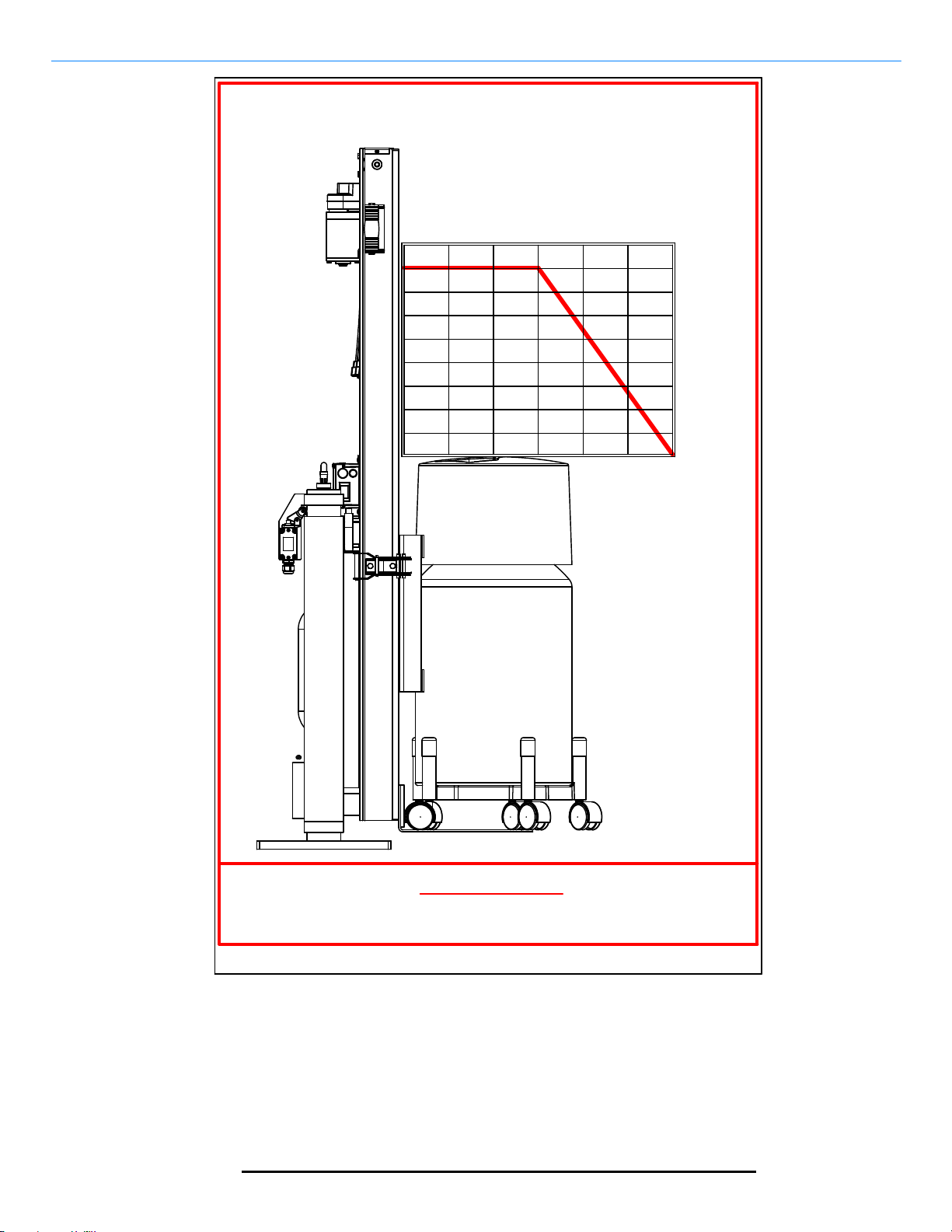
NOTE: This is a copy of the Load Chart on the Outer Frame of the Lift Gate Unit.
INSTRUCTIONS:
The above Loading Chart, shown with an example cylinder load, indicates the maximum load
that can be liftedby the LiftGate Unit at a specific center of gravity. The center of gravity is
measured as the distance from face of the Toeplate to the balance point of the load. Estimate
the weight of the load and the center of gravity distance out from the face of the Toeplate.
Locate on the chart the Weight/Center of Gravity location for the load. The load must not
exceed the weight limit for the given center of gravity distance.
POWERMATE 250Lb. LIFTGATE LOAD CHART
3.02
PN 018310 Rev.D2
Eng. 01 / 10/ 13
PowerMate®LiftGate™ Installation & Operation Manual
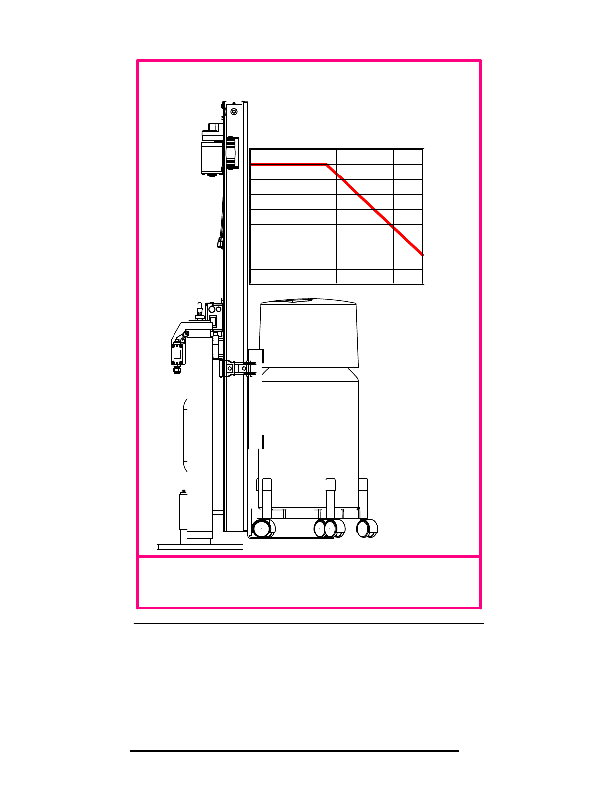
POWERMATE
LIFT GATE 500Lb.(227kg.) SERIES
E
C
A
F
E
T
A
L
P
LOAD CENTER OF GRAVITY
E
O
4"
T
500(227)Max.
8"
12"
16"
18"
24"
500(227)
400(181)
300(136)
200(91)
100(45)
LOAD
lbs.(kgs.)
WARNING
LOAD MUST BE SECURED TO THE UNIT WITH
THE RATCHET STRAP PROVIDED.
NOTE: This is a copy of the Load Chart on the Outer Frame of the Lift Gate Unit.
INSTRUCTIONS:
The above Loading Chart, shown with an example cylinder load, indicates the maximum load
that can be liftedby the LiftGate Unit at a specific center of gravity. The center of gravity is
measured as the distance from face of the Toeplate to the balance point of the load. Estimate
the weight of the load and the center of gravity distance out from the face of the Toeplate.
Locate on the chart the Weight/Center of Gravity location for the load. The load must not
exceed the weight limit for the given center of gravity distance.
POWERMATE 500Lb. LIFTGATE LOAD CHART
3.03
PN 018320 Rev.D2
Eng. 01/ 10/ 13
 Loading...