

Powermate L1 series, L2 series Repair Manual
L1/L2 Series Model
Repair Manual
PowerMate®/LP International Inc.
P.O. Box 696, 151 Savannah Oaks Drive
Tel: (519) 759-3292 Fax: (519) 759-3298 Toll: 1-800-697-6283
Website: www.PowerMate.info Email: info@powermate.info
Brantford, ON, CA N3T5P9
Create Date: March 06/2007

PowerMate® L1/L2 Series Model
Repair Manual
TABLE OF CONTENTS
Section A:
Trouble Shooting.....................................................................................PAGE 3
Trouble Shooting (con’t)..........................................................................PAGE 4
Section B:
Switch/Charge Plug Replacement L-1....................................................PAGE 5
Section C:
Bottom Guard Replacement...................................................................PAGE 6
Section D:
Strap Replacement.................................................................................PAGE 7
Section E:
Solenoid Replacement............................................................................PAGE 8
Section F:
Relay Replacement.................................................................................PAGE 9
Section G:
Fuse Assembly Replacement...............................................................PAGE 10
Section H:
Override Bearing Replacement.............................................................PAGE 11
Override Bearing Replacement (con’t)..................................................PAGE 12
Section I:
Motor Brush Replacement....................................................................PAGE 12
Motor Brush Replacement....................................................................PAGE 13
Motor Brush Replacement (con’t).........................................................PAGE 14
Section J:
Drive Screw Assembly Replacement....................................................PAGE 15
Section K:
Brake Assembly Replacement..............................................................PAGE 16
Section L:
Ballnut Lock Adjustment........................................................................PAGE 17
Section M:
Ballnut Bracket Replacement................................................................PAGE 17
Ballnut Bracket Replacement (con’t).....................................................PAGE 18
Ballnut Bracket Replacement (con’t).....................................................PAGE 19
Installation of Sealed Batteries Diagram...............................................PAGE 19
Page 2 of 19

PowerMate® L1/L2 Series Model
Repair Manual
Section A: Trouble Shooting
Switches
Both Switches Inoperative
A. Check and replace fuse if necessary with 30A automotive fuse.
B. Test battery and or batteries.
C. Wiggle and visual test of wiring for loose, pinched or broken wires.
D. Motor brushes
One Switch Inoperative
E. Bypass Switch: Cross the two terminals on the bottom of the suspect switch with a wrench or screwdriver. If
the machine works, switch is faulty. See Switch/Charge Plug replacement. Continue troubleshooting relay and
solenoids if the machine is still inoperative.
Relay and Solenoids
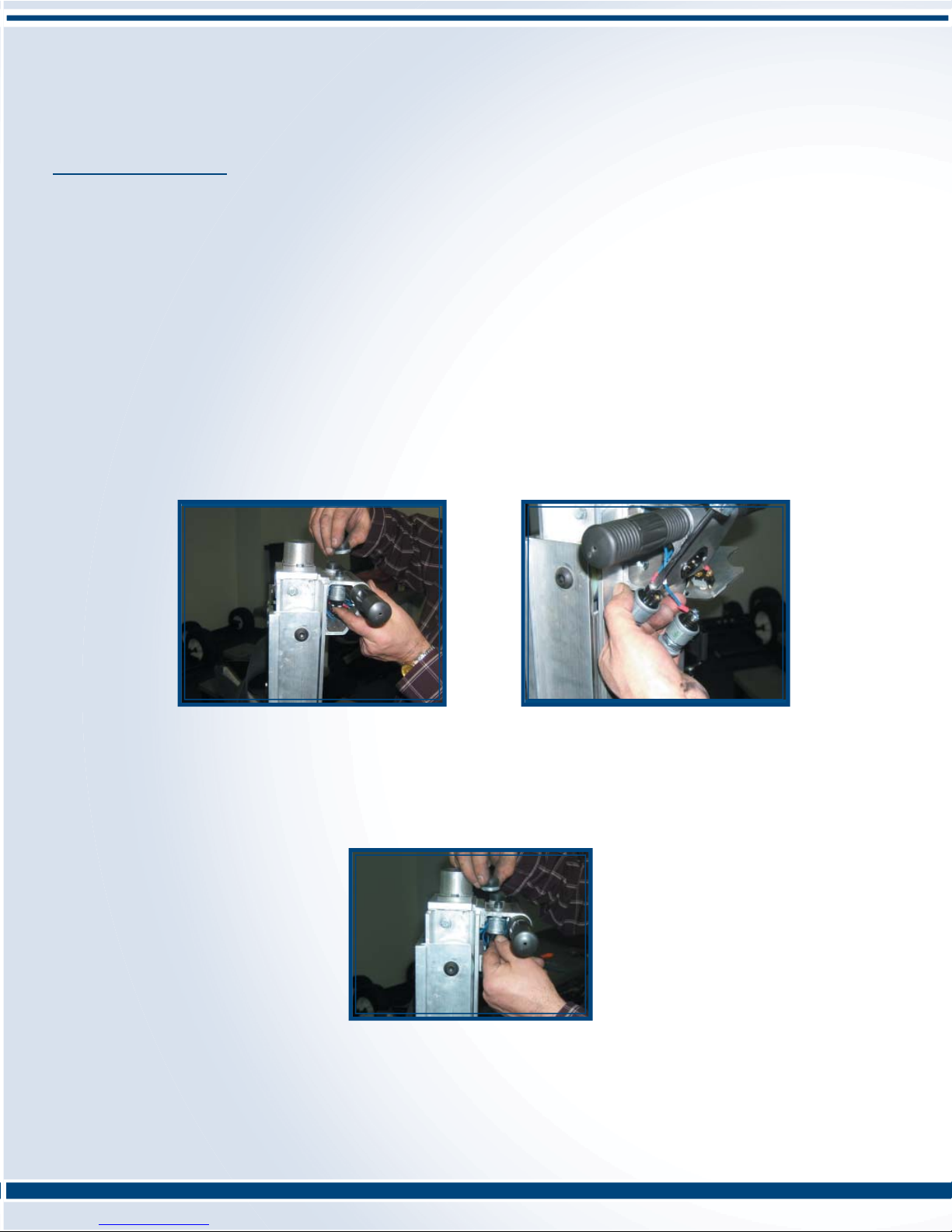
A. Bypass Relay: **Special Note: When performing this test, do not push both push button
switches at the same time.
Remove two wires (refer to diagram) and join together. Push the suspect switch. If the
switch works, the relay is faulty. See Relay Replacement. Continue troubleshooting if the
machine is still inoperative.
A
B
B. Bypass Solenoid: **Special Note: This is a test that will require two people.**
This test also requires one 6-8” length of 10G wire. The solenoid(s) to be tested will be determined by the type of
machine and the suspect switch (open or close), refer to appropriate diagram.
iii. L-Series Open switch (wheels up/load down) 2 solenoids bottom of the pack
iv. L-Series Close Switch (wheels down/load up) 2 solenoids top of the pack
1. Depress and hold down the suspect switch.
2. Take the 10G wire and make contact on the large posts of one of the two solenoids. If the machine operates, the
solenoid is faulty. See Solenoid Replacement. If the machine is still inoperative repeat steps on the next solenoid.
**NOTE: Though slight, there is a possibility of both solenoids inoperative, check both.
Machine Will Not Lift a Load
Drive Screw Spinning
A. Ballnut locknut is too loose. To tighten see Ballnut Locknut Adjustment.
B. If the above does not solve the problem, the ballnut will have to be replaced. See Ballnut Replacement.
Drive Screw NOT Spinning
C. If the motor is spinning but not the drive screw:
1. L-Series : Check brake assembly kit and replace if damaged. See Brake Assembly Replacement.
Also, if the brake assembly is damaged check and ensure the drive screw is still connected to the motor.
2. Check roll pin in the coupling. Replace if sheared or misshapen.
3. Check coupling and replace if stripped.
4. Check motor spline and replace if stripped.
D. If the motor is not spinning, check the battery and replace if necessary.
Page 3 of 19

PowerMate® L1/L2 Series Model
Repair Manual
Section A: Trouble Shooting Continued
Machine is Fully Open and Will Not Close
A. If the drive screw just spins, the ballnut locknut is too loose. See Ballnut Locknut Adjustment.
B. If the drive screw does not spin, the ballnut locknut is too tight. See Ballnut Locknut Adjustment.
Urethane Bumper is Squashed
A. Ballnut locknut is too tight. See Ballnut Locknut Adjustment.
B. Check the spring washer in the override bearing kit for fl atness. If the spring washer has fl attened, see Override
Bearing Assembly Replacement.
Machine Operates Intermittently
A. If the machine is used quite extensively and or is older, the problem will more that likely be motor brushes.
See Motor Brush Replacement.
B. If machine is new, wiggle check and visually inspect for loose pinched or broken wiring, also,
see Relay and Solenoids.
Load Drifts Down
A. Check Brake Assembly Kit for sheared or misshapen roll pin and or damaged spring. Replace Brake Assembly
Kit if necessary. See Brake Assembly Replacement.
Machine Makes a Grinding Noise When Opening & Closing
A. On a M-Series the inner frame is probably bent. The proper measurement on the inner frame will be 14” from the
outside of the frame. If a minimum 16” C or Bessey clamp is available, repair can be completed by the customer.
The bend is usually at or around the battery box. Open the machine enough to attach the clamp to where the
battery box is welded. Close the clamp to 13.5”. The frame will spring back to around 14”. If clamp is not
available, return to L P for repair.
Brake Cap Gets Hot During Normal Use
A. Check Brake Assembly Kit for sheared or misshapen roll pin and or damaged spring. Replace Brake Assembly
Kit if necessary. See Brake Assembly Replacement.
Wheel Brakes Flip Over During Normal Use
A. Check and replace green urethane stop if necessary.
B. Coupling on brake shoe needs adjustment. Bend coupling slightly towards the wheel axle.
See diagram for details.
Charging System
A. Machine will not accept a charge.
1. Check fuse and replace with 30A automotive fuse if necessary.
2. Wiggle and visual test of wiring for loose, pinched or broken wires.
3. Check wiring inside of charger plug. Refer to the back of the charger for positive and negative
wire colors. The positive wire will go the large prong and the negative to the center.
4. Check the battery(s). If Amps are too low, battery will not charge. See Installation of Sealed
Batteries Diagram.
Page 4 of 19
PowerMate® L1/L2 Series Model
Repair Manual
Section B: Switch/Charge Plug Replacement L-1
PROCEDURE:
*NOTE: Remove the fuse prior to any maintenance on this equipment.
1. Remove the two Handle Housing Covers by removing the four screws.
TOGGLE SWITCH
2. Remove the Nut retaining the Toggle Switch, and dis-engage the Toggle Switch from the Handle Housing Cover.
If the Toggle Switch replacement is required, remove the two switch wires and replace the Toggle Switch at this
time.
PUSH BUTTON SWITCH
3. Unscrew the Rubber Covers and remove the Push Button Switches out of the side of the Handle Housing.
Install new Push Button Switches, swapping one wire at a time to maintain proper order.
NOTE: Do not remove any wires unless the switch is to be replaced.
CHARGE PLUG
4. If the Charge Plug requires replacement, remove the two 6-32NC nuts and screws and pull out the charge plug
with wires.
5. Transfer wires from the charge plug to the replacement charge plug maintaining wire placement. Re-install the
plug into the Handle Housing, insert the two 6-32NC Screws and secure with the two N-32NC Nuts.
6. Insert the push button Switches into the Handle Housing and secure with the Rubber Covers.
7. Insert the Toggle Switch into the handle Housing Cover and turn with the Switch Nut.
8. Attach the Handle Housing Covers securing with the 10-24NC Screws.
9. Re-install the fuse and test.
Page 5 of 19
PowerMate® L1/L2 Series Model
Repair Manual
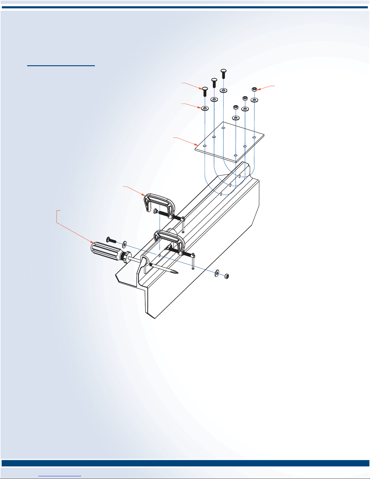
Section C: Bottom Guard Replacement
(6) 1/4-20NC x 7/8"Carraige Bolt
(2) 2"C-Clamp
1/4"Alignment Device
-Phillips Screw Driver shown.
-2 required.
(6) 1/4-20NC Nut
(12) 1/4"Plate Washer
(2) Rubber Guard
PROCEDURE:
Tools required: Two 1/4"drifts, screwdrivers(phillips), or pry type tools.
-used to pull and align holes in rubber to holes in toeplate.
- 7/16"socket wrench.
- Two 2" C-clamps.
1. Extend PowerMate unit approximately 15"and rest the unit face down(wheels up)
on a suitable work surface. The floor may also be used. Note: The view above is
shown as the toeplate only for clarity.
2. Remove the 1/4"Nuts with the 7/16"wrench and dis-assemble the old Rubber Guard.
3. Use the screw driver type tools to align the holes of the new Rubber Guard and the Toeplate.
4. Apply the two 2"C-Clamps either side of the center hole leaving room to apply a Washer.
5. Insert a Carriage Bolt and Washer through the center hole as shown, and place a Washer
on the exposed thread. Applying thumb pressure to the head of the Bolt, start the 1/4"Nut
onto the thread. Remove the C-Clamps and tighten the 1/4"Nut with the 7/16"wre nch.
6. Re-install the C-Clamps adjacent to another hole, remove the alignment device, and repeat
the Bolt installation step 5.
BOTTOM GUARD REPLACEMENT
Replacement Kit No. 410060
Page 6 of 19
 Loading...