

PowerMaster PM-SBC-2012, PM-SBC-4012F, PM-SBC-6012F, PM-SBC-1524, PM-SBC-3024F User Manual
...Page 1
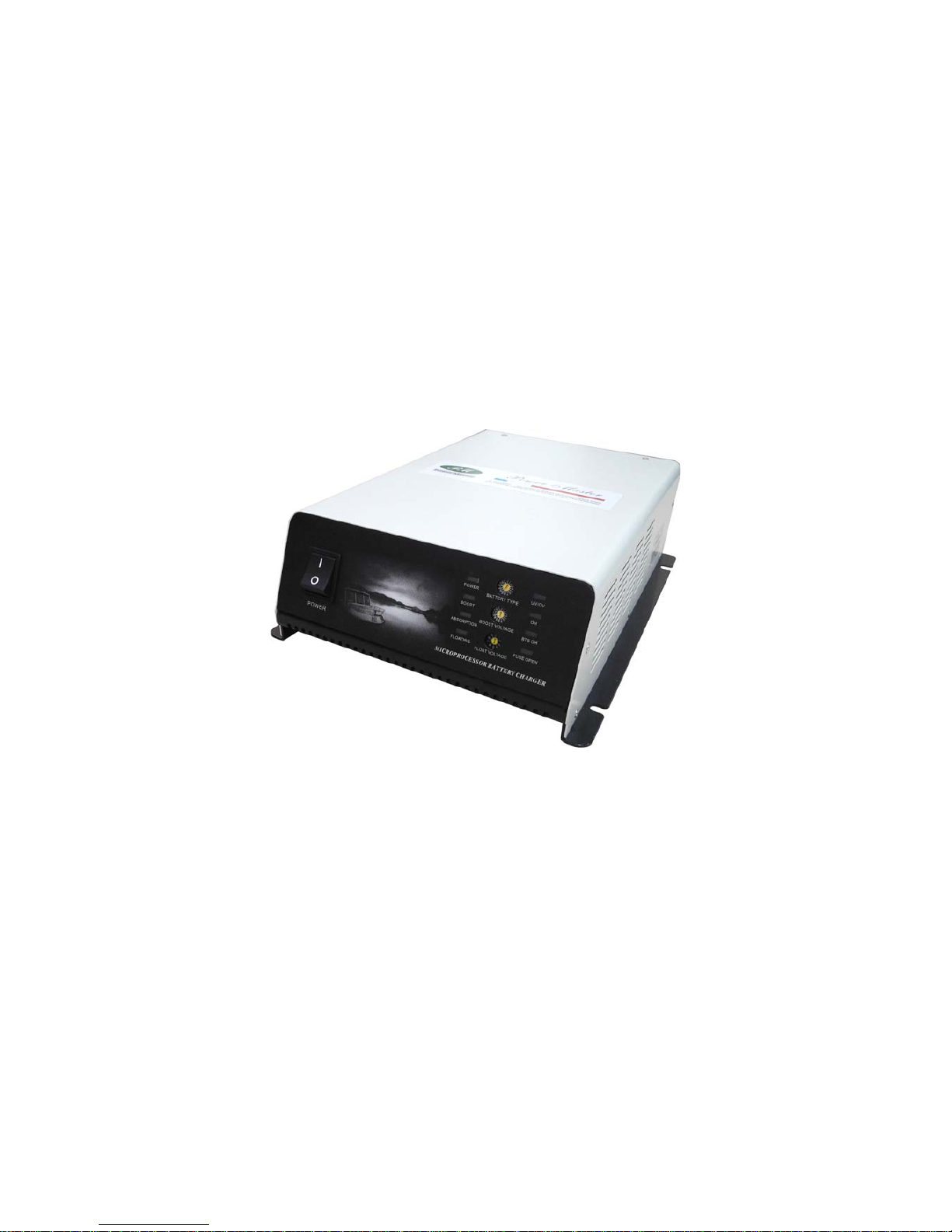
SWITCH-MODE BATTERY CHARGER
(MICROPROCESSOR SYSTEM)
USER MANUAL
FOR ALL PATTERNS 1 AND 3 OUTPUTS
Page 2

1
CONTENTS
Introduction............................................................................................................2
Technical Features.................................................................................................2
Advanced Charging Technique ............................................................................ 3
Safety Devices.........................................................................................................3
Options....................................................................................................................4
Safety Instruction...................................................................................................4
Installation..............................................................................................................5
Front Panel.............................................................................................................7
LED Indicators.......................................................................................... ............. 7
Switches Section (4 Battery Types and 1 User Define) .......................................7
Instruction of Charging Curve Selection.............................................................8
DC Power Supply................................................................................................... 9
BTS/Remote Control ...........................................................................................10
Trouble Shooting Guide......................................................................................10
Specification .............................................................. ................ ................ ........... 11
Page 3

2
Introduction
Power Master Battery Charger is small and lightweight charger that offers charging
patterns which are perfectly adapted to each battery technology (liquid electrolyte, gel
electrolyte, lead calcium, etc... ). A charging pattern may be factory set to suit your
specific application.
To prolong the life of your batteries and conserve their initial
capacity, the charger is programmed
with 5 three-state charging patterns:
z BOOST Charge/FAST Charge :Restores battery capacity until 80 % in a short
space of time.
z ABSORPTION Charge/BALANCE Charge : Complements of charge until 100 %
of battery capacity
z FLOATING Charge/TOP-UP Charge : Compensates for constant battery drain,
while keeping the battery fully charged.
Power Master Battery Charger is the only charger on the market to allow the battery to
be connected and used constantly, while still offering a real BOOST (high voltage)
charge over short period. The charger switches back to top-up mode automatically.
In accordance with EC standards, the Power Master Battery charger is fitted with a PFC
(Power Factor Corrector) which limit peak current draw from the input power required
from the generator or Mains supply to be reduced.
Technical Features
- Management and control by microprocessor
- Charging curve of 3 states IUU type
- UNIVERSAL input voltage 90V to 250Vac (item 12V/40A, 12V/60A, 24V/30A,
24V/50A)
- Input voltage 230V ~ +10%/-15% (item 12V/20A, 24V/15A )
- Frequency 50/60Hz
- Output voltage Ubat ±1% ; output current Ibat ±10%
- Operating temperature -10 to + 45°C; storage temperature -20 to +70°C
- Charging curve selection by rotate switch for 5 different batteries types
- Sensor used to balance charging voltage according to temperature gaps (-27mV/°C)
- Automatic air vented cooling
- Protection Index IP 235
Page 4
3
Advanced Charging Technique
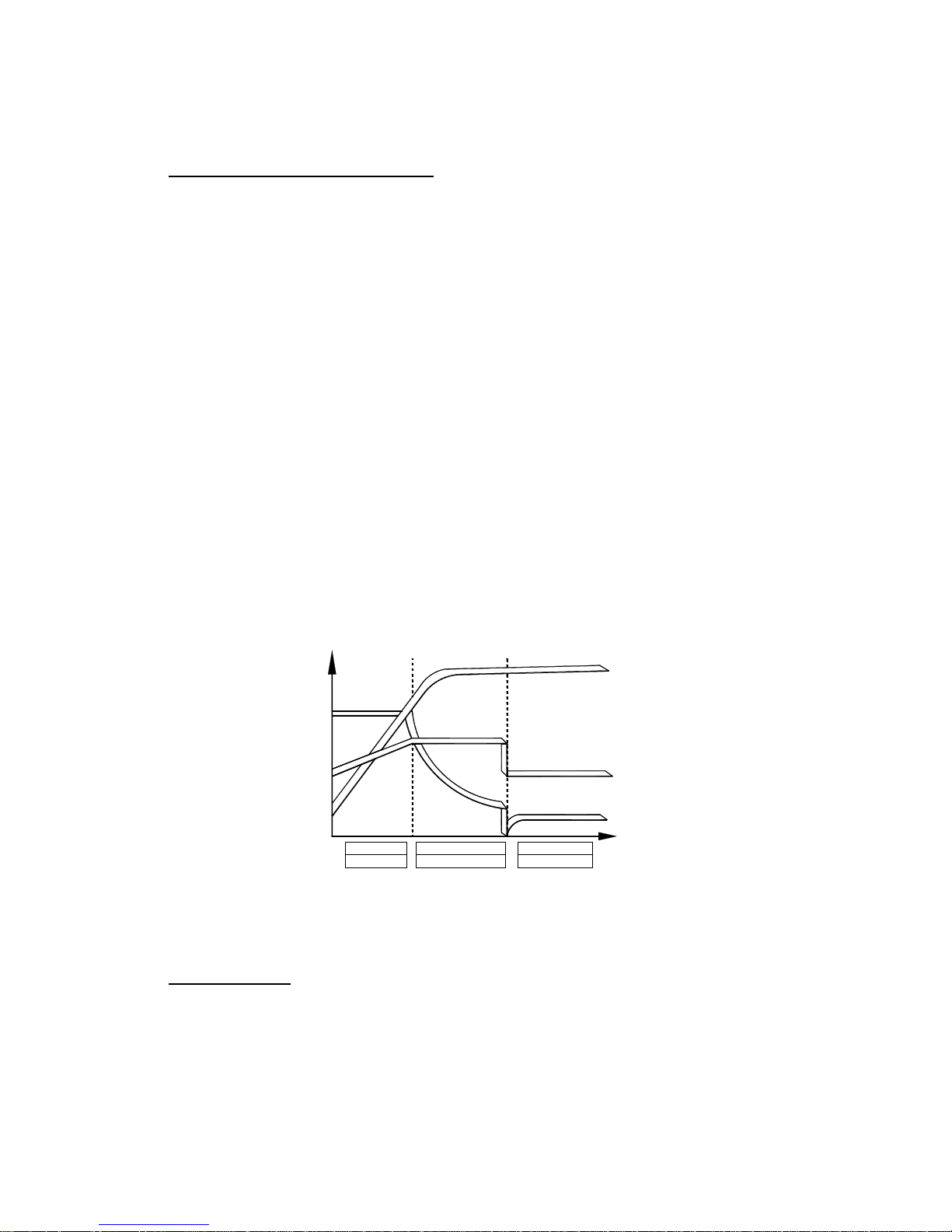
Charging curves of the 3-state IUU type, with a boost phase and a floating phase.
The 3-state charging characteristic, used on boats everywhere, saves on charging time. In
addition, the charger can be adapted to all types of battery thanks to its 5 integral
charging curves supervised by a micro controller. Charge cycle starts on with the mains
power-up of product.
Boost Phase
Charging continues at constant current (charger Inom) until the battery reaches the
maximum boost voltage. This voltage is maintained until the charging current falls to
Inom/8 ~Inom/10 boost charge over short period (12 hours) from the mains power-up of
product. This phase makes it possible to supply the maximum amount of energy in the
least possible time.
Floating Phase
The charger supplies just the current necessary to keep the battery at a constant and stable
voltage (floating voltage). This charging mode allows 12-volt equipment to be used
continuously (water pump, refrigeration, auto pilot, radio, lights, etc.) without the
batteries discharging.
It means that the on-board circuit can be used while keeping the battery charge level
constant. WITHOUT BATTERY AND IN SPECIAL CIRCUMSTANCES, THE
POWER MASTER CHARGER SUPPLIES STABLE VOLTAGE.
General form of the charging curve (five possible levels according to battery type)
Top-up ChargeBalance Charge
Fast Charge
CURRENT
VOLTAGE
CAPACITY Ah
BOOTS
ABSORPTION
FLOATING
Charging Current
The nominal current shown in case of nominal voltage is the mean current supplied by
the charger.
Safety Devices
Electronic protection against:
- Output short-circuits
- Battery discharge in the event of mains failure
Page 5

4
Disjonction protection against:
- Battery overvoltage or undervoltage
- Battery or charger overtemperature
Protection by fuses against :
- Mains input overload
- Battery polarity inversion
Anti-corrosion
Casing in aluminum with anti-corrosion paint.
Anti-impact
Resistance to impacts in normal use thanks to the 2 mm-thick casing (1,5mm for the
cover).
Ventilation
If the internal charger sensor exceeds 60°C, fan starts
Options
1. Battery Temperature Sensor (BTS):
Sensor is used to balance charging voltage according to temperature gaps, compared
with reference temperature 25°C. If temperature exceeds 45°C, charging stops and
LED of BTS OH flashes. Charging restarts when temperature is less than 45°C.
Procedure of connecting BTS is:
1. Disconnect the charger from the mains (MANDATORY). To avoid short-circuit,
disconnect the batteries.
2. Extract fixing screw from wires cover and remove it
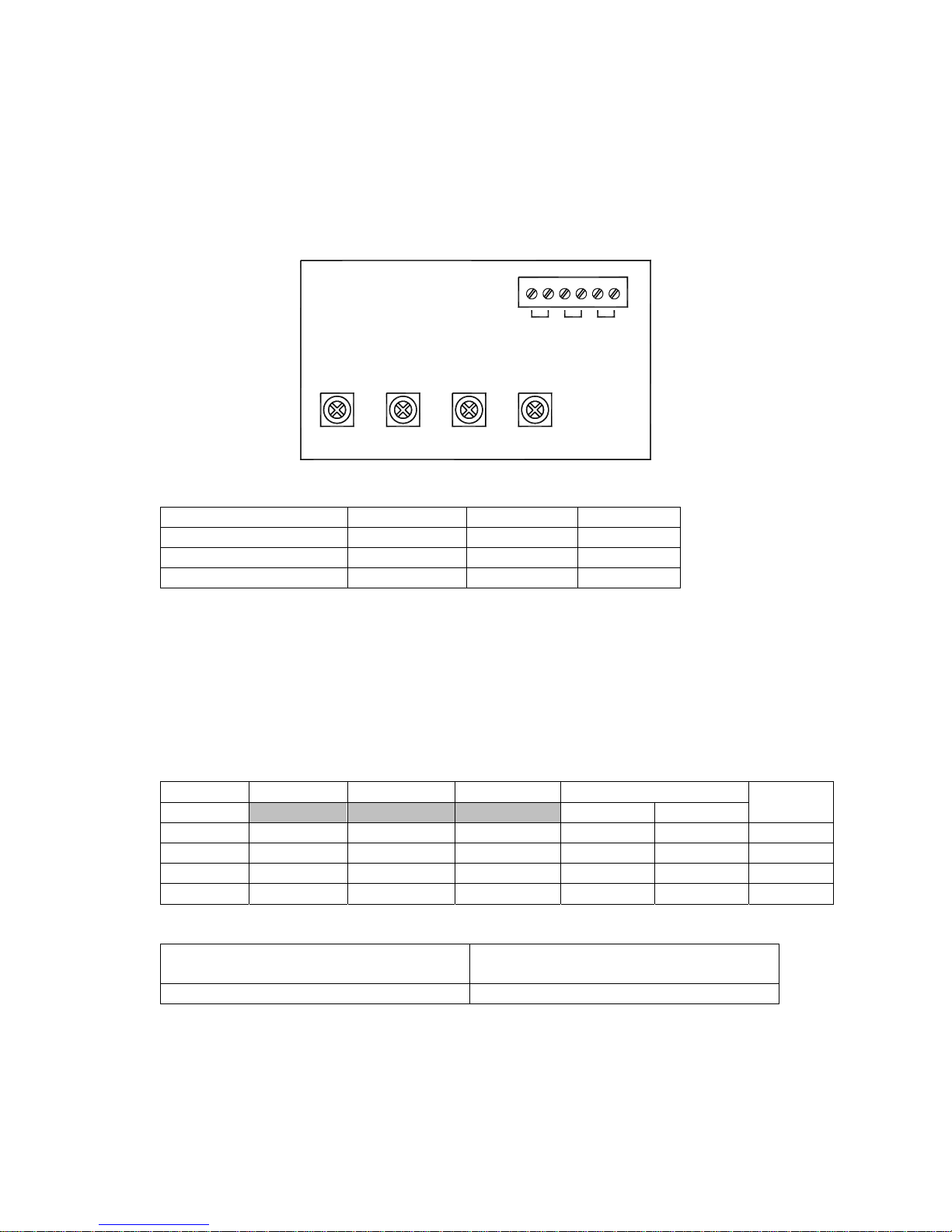
3. Connect the sensor connector to the green terminal on the card (see figure A)
4. Connect charger to the mains
5. Fix the temperature sensor(s) on corresponding battery(ies) with double-sided
adhesive tape supplied with sensor.
To disconnect sensor from the charger, charger must be disconnect from the mains
before (even if the charger indicates a default).
CAUTION: In case of fault, charger switches off automatically. Disconnect charger from
mains then wait for approximately 10 minutes before starting it again.
2. Remote Control: It can be connected to the Power Master charger. All operating
controls and displays are available on the remote control unit.
Safety Instruction
A battery can generate gas in the case of high overcharge, that can be explosive.
Attention must be paid to produce no spark or flame near a battery on charge, arrange for
a well-ventilated room.
Power Master charger limits overcharges and reduces this risk.
z Excessive discharges are among the principal causes of premature wear.
Power Master charger prevents such excessive discharge. After every discharge,
(especially higher than 50%), recharging should not be deferred for a long time.
z Low and permanent overcharge is another cause of premature wear. The Power
Page 6

5
Master Charger delivers the current necessary for battery charge and adapts itself to
supply the optimum end of charge.
z The accidental and violent overcharge or higher end of charge current produces early
destruction by excessive rise of temperature. The temperature should not exceed 50°C.
By the regulation of the current, the Power Master protects the battery from the
temperature rise at the end of charge.
It is advisable to
z Put batteries in a well ventilated area
z Not to smoke near batteries
z Take the battery manufacturer prescriptions into consideration
Accidental Leakage Current between Line And Earth
z Connections will be realized by an electrician or a professional installer.
z The charger must be connected to a system having a two-pole differential circuit
breaker with 30 mA sensitivity.
Accidental Leakage Current Between Charge Cir cuit and Earth
z To detect accidental leakage currents to earth, you must use a safety device outside
the charger.
z The rating and nature of the protection must be ensured by the installer.
z Special precautions are recommended on any installation where there is a danger of
electrolytic effects.
z Regulations require the presence of a battery cut-out on the output + pole and on
the output – pole.
Precautions Regarding Lightning Strike
In geographic zones exposed to a high risk of lightning strikes, it may be recommended
fitting a lightning conductor on the inlet side of the charger. Power Master will not take
charge of damaged caused by lightning strike.
Precautions Regarding Electromagnetic Interference
z Make sure the length of the cables and screening connections are kept as short as
possible.
z Separate the power supply cables from output cables.
z Cables must only carry the charger power supply. Branch or bridging connections in
order to supply another equipment are too be banned.
Installation
The location of the Power Master charger must be chosen by the following criteria:
Protection from unauthorized handling.
Dry dust free room, no condensation, no rodents.
Keep ventilation holes free. The ventilation of the Power Master is designed in such a
way that it will work most efficiently when mounted horizontally.
Before any connection, put the switch on the right charging curve.
1. Connect the positive battery on terminal marker +BAT 1 and open the entry of the
upper case to tighten it with screws.
Page 7
6
2. Connect the negative battery cable to terminal marker –BAT and open the entry of the
upper case to tighten it with screws.
3. Do the same for batteries number 2 and 3 for +BTA 2 and +BTA 3. For a 3 outputs
charger, refer to the table below to choose conductor section.
BTS3BTS2BTS1
-BAT+BAT1+BAT2+BAT3
Battery fuse board:
Model No. 12V/20A 12V/40A 12V/60A
FUSE Atofuse (car) 1 x 25A 2 x25A 2 x 30A
Model No. 24V/15A 24V/30A 24V/50A
FUSE Atofuse (car) 1 x 15A 2 x15A 2 x 30A
WARNING: Check carefully the tightness of the battery connections to the charger (risk
if not properly tightened). Power Master will not take charge of damage caused by a
bad tightness of connections.
Don’t connect a charge distributor on an Power Master char ge r, 1 or 3 outputs.
4. Put the AC plug in the rear panel. The charger operates on sector 90V to 250 Vac -
50/60 Hz. Use preferably cable H07rn-F with 3 conductors. Earth lead to be
connected to the terminal on the unit.
Length 5m 10m 15m Sector flex section (5m)
Current 220V 110V
Puissance
(W)
30A 6 mm2 10 mm
2
16 mm
2
1.5 mm2 2.5 mm2 750
40A 10 mm2 16 mm
2
25 mm
2
1.5 mm2 1.5 mm2 500
50A 16 mm2 25 mm
2
35 mm
2
1.5 mm2 2.5 mm2 1200
60A 25 mm2 25 mm
2
35 mm
2
1.5 mm2 2.5 mm2 750
Main fuse board:
Model No.
12V/20A, 12V/40A, 12V/40A,
24V/15A, 24V/30A, 24V/50A
Temporized glass fuse 6.3x32mm 16A
Page 8
7
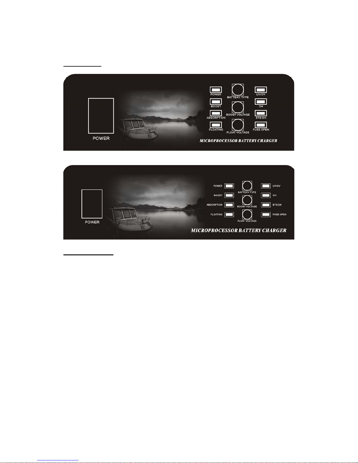
Front Panel
15A/24V, 20A/12V
30A/24V, 40A/12V, 50A/24V, 60A/12V
LED Indicators
POWER: It is lit when the AC power has been input through the AC plug.
BOOST: It is lit as long as the battery is not fully charged at set voltage.
ABSORPTION: It is lit as long as the battery is not fully charged at set voltage.
FLOATING: It is lit when the battery is fully charged.
UV/OV:
Under Voltage---Deep battery discharge Ubat < 10V for 12V system and < 20V for 24V
system. If Ubat stays < 10V for 12V system and < 20V for 24 system
during more than 5 minutes, charger shuts down. To restart the charger:
disconnect the mains, wait few minutes and reconnect the charger on
mains.
Over Voltage--- Battery overcharge Ubat > 16V for 12V system and > 32V for 24V
system. If Ubat > 16V for 12V system and > 32V for 24V system
during more than 5 minutes, charger shuts down. To restart the charger:
disconnect the mains, wait few minutes and reconnect the charger on
mains.
OH: Over Heat---It is flashing when the heatsink of the charger reaches > 70℃. The
charger shuts down when the charger is > 80℃.
BTS OH: Battery Temperature Sensor Over Heat--- It is flashing when the BTS reaches
> 45℃. The charger shuts down when the battery temperature is > 50℃.
Page 9

8
FUSE OPEN: Fuse is broken.
Switches Section (4 Battery Types and 1 User Define)
The great advances realized by manufacturers of batteries put at the disposal of users
batteries without maintenance, so it means a certain tranquillity for the user but impose,
however on the charger system, an exacting precision.
Every battery is designed according to particular technology and therefore calls for a
particular charging curve.
With Power Master battery charger, you can achieve this perfect match between battery
and charger using a switch, which is simply positioned according to the required,
charging curve.
Note: Do indicate the type of your battery when buying the charger, and position the
switch correctly before use.
Instruction of Charging Curve Selection
The user can very easily adapt the Power Master charger to the type of battery by rotate
switch used.
To modify configuration carryout the following steps:
STEP 1: Disconnect charger from the mains. To avoid short-circuit, disconnect the
batteries.
STEP 2: According to 4 different battery types and desired charge current (30%, 70% and
100%), choose the rotate switch from 1 to C. If the used battery is not in 4 listed
battery types, User Define is available.
Battery Type U Boost U Float
Charge
Current
Rotate
Switch
14.4V 13.5V 100% 1
14.4V 13.5V 70% 2
Sealed lead, maintenance-free
gel type
14.4V 13.5V 30% 3
14.2V 13.8V 100% 4
14.2V 13.8V 70% 5
Classical lead open
14.2V 13.8V 30% 6
14.6V 14.0V 100% 7
14.6V 14.0V 70% 8
Lead calcium
(standard charge )
14.6V 14.0V 30% 9
16.0V 13.8V 100% A
16.0V 13.8V 70% B
Lead calcium *
DEEP DISCHARGE
16.0V 13.8V 30% C
─ ─ 100% D
─ ─ 70% E
User Define
─ ─ 30% F
User Define: Use the switches of the BOOST VOLTAGE and FLOAT VOLTAGE to
choose desired voltages from the following tables.
Page 10

9
BOOST VOLTAGE Selection
Rotate
Switch
Boost
Volt.
Rotate
Switch
Boost
Volt.
Rotate
Switch
Boost
Volt.
Rotate
Switch
Boost
Volt.
0 14.4V 5 14.9V A 15.4V F 14.3V
1 14.5V 6 15.0V B 15.6V
2 14.6V 7 15.1V C 15.8V
3 14.7V 8 15.2V D 16.0V
4 14.8V 9 15.3V E 14.2V
FLOAT VOLTAGE Selection
Rotate Switch Floating Volt. Rotate Switch Floating Volt.
0 13.5V 5 14.0V
1 13.6V 6 13.1V
2 13.7V 7 13.2V
3 13.8V 8 13.3V
4 13.9V 9 13.4V
STEP 3: Connect charger to the mains.
Example:
To use the Power Master charger of 12V/40A to charge a battery of Classical lead open at
desired charging current 28A, users should choose rotate switch of battery type to be “5”.
DC Power Supply
Power Master charger can not only charge the battery but also supply DC power directly.
The desired voltage can be set by the following steps.
STEP 1: Choose the rotate switch of BATTERY TYPE to be“0".
STEP 2: Use the rotate switch (0~F) of BOOST VOLTAGE to set the first two digits of
desired voltage. Refer to the below table for what 0~F represents.
Rotate
Switch
Boost
Volt.
Rotate
Switch
Boost
Volt.
Rotate
Switch
Boost
Volt.
Rotate
Switch
Boost
Volt.
0 13.0V 5 16.0V A 16.0V F 16.0V
1 14.0V 6 16.0V B 16.0V
2 15.0V 7 16.0V C 16.0V
3 16.0V 8 16.0V D 16.0V
4 16.0V 9 16.0V E 16.0V
STEP 3: Use the rotate switch (0~9) of FLOAT VOLTAGE to set the decimal of desired
voltage. Refer to the below table for what 0~9 represents.
Rotate Switch Floating Volt. Rotate Switch Floating Volt.
0 0.0V 5 0.5V
1 0.1V 6 0.6V
Page 11

10
2 0.2V 7 0.7V
3 0.3V 8 0.8V
4 0.4V 9 0.9V
Example:
To set the desired DC power supply of 14.3V, firstly, choose the rotate switch of battery
type to be“0"and then choose the rotate switch of boost voltage to be“1"; finally,
choose the rotate switch of float voltage to be“3".
BTS/Remote Control
It is a port for phone jack of the battery temperature sensor and upcoming remote control
to be connected.
Troubleshooting Guide
Problem and Symptoms Possible Cause Solution
No alternative current or
main fuse is melted down
Check the fuse and replace
it
No output voltage and/or
intensity
Main or generating unit too
weak
Check the input voltage
Battery consumption > power
of the charger
Reduce the consumption on
the battery
Charger delivers a weak
output voltage but a max.
intensity
One or several elements of
the battery present a
short-circuit
Check that there 's no
increase of battery
temperature
Battery is almost totally
charged
Check that the charger is on
a floating mode
Intensity of charge is too
weak < 10%
Alimentation is too weak Check the input voltage
Consumption on the battery
during the charge is too
important
Decrease the consumption
Time of charge is too short
Choose a more powerful
charger
Battery temperature too weak Use a temperature sensor
Battery is never totally
charged
Defective battery Change the battery
Loss (emission of gas)
Change the battery or check
the level of water
Battery is quickly empty
Sulfate on / stagnation
Charge / discharge several
time the battery or check
the charging curve or
replace the battery
Defective battery Replace the battery
Battery is hot/emission of
gas
Temperature of the battery is
too high
Use a temperature sensor
and/or check the charging
curve
Page 12

11
The charger is near to the
"switch off" temperature
Ventilate the charger
Red LED DEFAULT
flashes
Battery temperature is too
high (with a temperature
sensor)
Check the charging curve
and placed the battery in a
ventilated area
All LEDS are flashing but
the charger doesn’t charge
Default of the battery which
is in deep discharged or
polarity inversion of the
battery
Check the connection of the
battery, the polarity and
the output fuse
Problem and Symptoms Possible Cause Solution
All LEDS are flashing but
the charger doesn't charge
DEFAULT
Check the battery
connections and the
connection of display, and
check the output fuse
No LED is lighting when
the charger is connected to
the main
DEFAULT
Check the main input, the
connection of display and
the fuses.
During the charge, all
LEDS are switched off
Stop because of the thermic
security or battery voltage <
9 V
( 18V for a 24V battery )
disconnect the charger, wait
20 minutes and connect to
the main
Page 13

12
Specifications
Output: 12V
Model No. PM-SBC-2012 PM-SBC-4012F PM-SBC-6012F
Input Voltage
Input voltage
230V ~
+10%/-15%
Universal input:
90V to 250V
Output Voltage
12V
Charging Capacity
20A 40A 60A
Frequency
50Hz/60Hz
Output Patterns
1 or 3
Input Voltage U bat
+/-2%
Output Current I bat
+/-10%
Charging Curve Type
3 states IUU type
(Boost Charge, Absorption Charge, Floating Charge)
Charging Curve Selection
By SWITCH for 5 different battery types:
Classical lead open, sealed lead/gel, lead calcium
standard charge, lead calcium deep discharge, user define
Working Temperature
-10℃ ~ +45℃
Storage Temperature
-20℃ ~ +70℃
Protection Feature
Against output short-circuit, battery discharge in the event of
mains failure, mains input overload, battery polarity inversion
Protection Options
Battery or charger overtemperature
(Temperature sensor)
Dimensions
310x200x70 mm 400x250x80mm 400x250x80 mm
Weight
3 kgs 6 kgs 6 kgs
Page 14
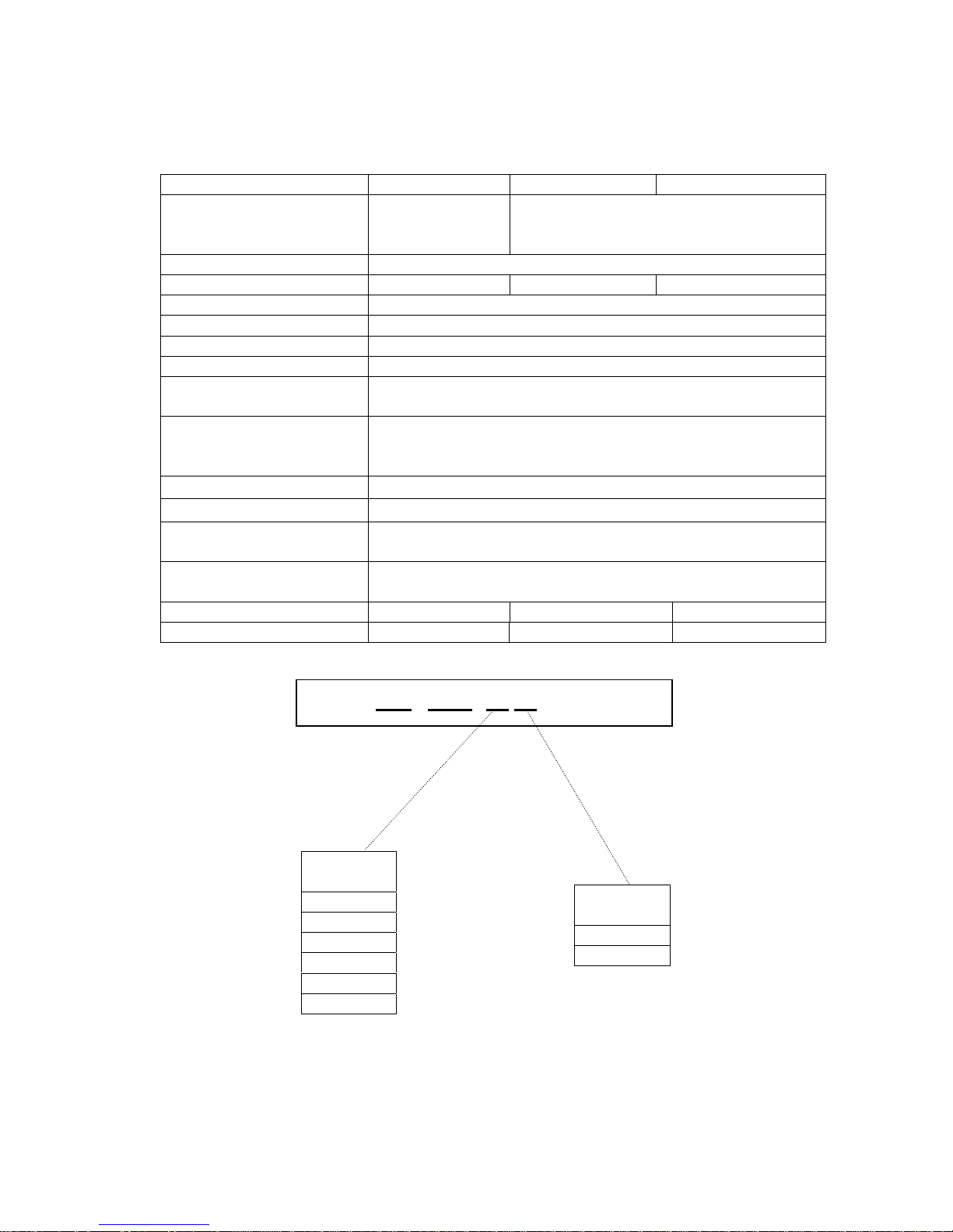
13
Output: 24V
Model No. PM-SBC-1524 PM-SBC-3024F PM-SBC-5024F
Input Voltage
Input voltage
230V ~
+10%/-15%
Universal input:
90V to 250V
Output Voltage
24V
Charging Capacity
15A 30A 50A
Frequency
50Hz/60Hz
Output Patterns
1 or 3
Input Voltage U bat
+/-2%
Output Current I bat
+/-10%
Charging Curve Type
3 states IUU type
(Boost Charge, Absorption Charge, Floating Charge)
Charging Curve Selection
By SWITCH for 5 different battery types:
Classical lead open, sealed lead/gel, lead calcium
standard charge, lead calcium deep discharge, user define
Working Temperature
-10℃ ~ +45℃
Storage Temperature
-20℃ ~ +70℃
Protection Feature
Against output short-circuit, battery discharge in the event of
mains failure, mains input overload, battery polarity inversion
Protection Options
Battery or charger overtemperature
(Battery Temperature Sensor)
Dimensions
310x200x70 mm 400x250x80mm 400x250x80 mm
Weight
3 kgs 6 kgs 6 kgs
CHARGE
CURRENT
15A
20A
30A
40A
50A
60A
OUTPUT
VOLTAGE
12VDC
24VDC
PM –SBC- 20 12
 Loading...