

PowerLogic™ Power Meter PM5350
User Guide
63230-401-203A5
03/2021

Safety Information
Important Information
Read these instructions carefully and look at the equipment to become
familiar with the device before trying to install, operate, service or maintain it.
The following special messages may appear throughout this manual or on
the equipment to warn of potential hazards or to call attention to information
that clarifies or simplifies a procedure.
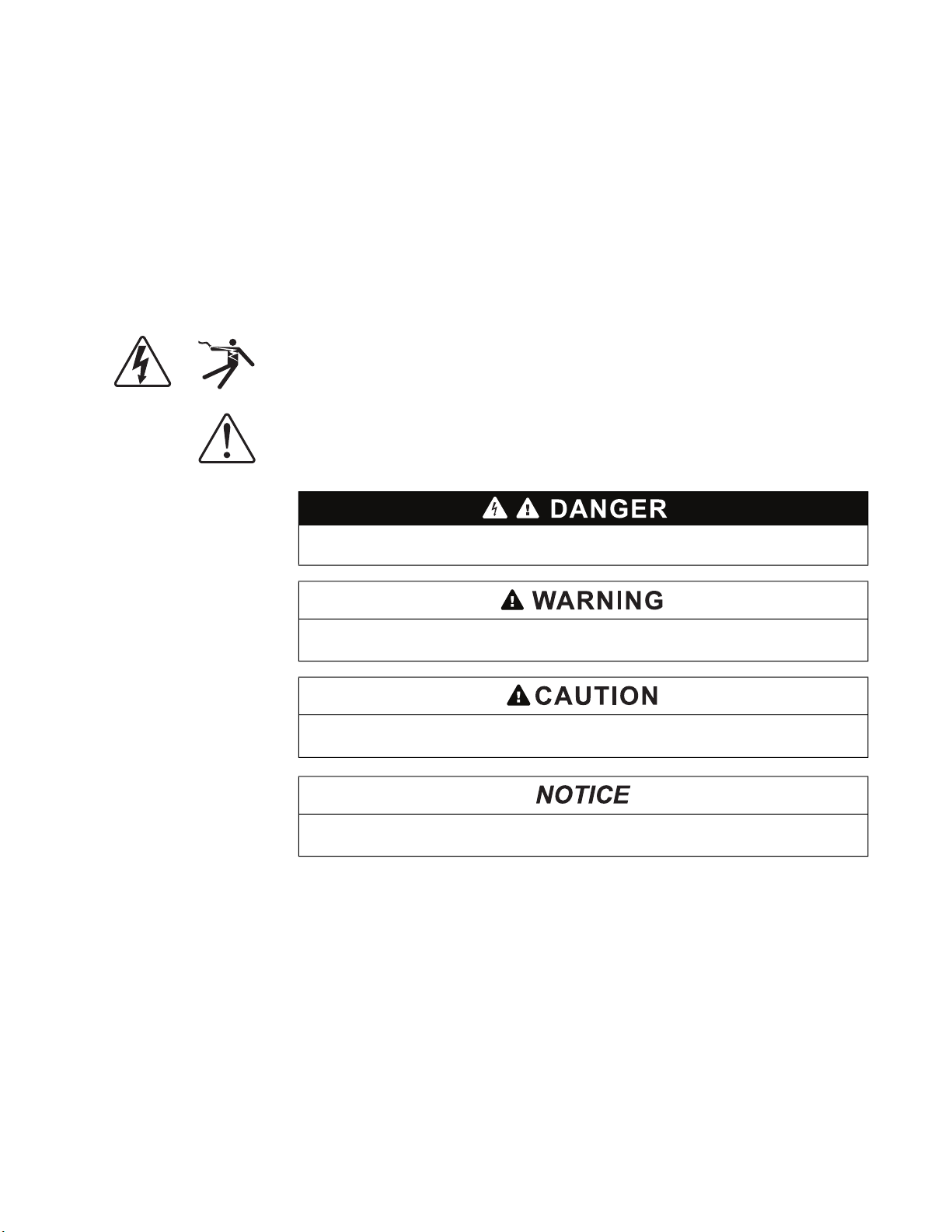
The addition of either symbol to a “Danger” or “Warning” safety label indicates that
an electrical hazard exists which will result in personal injury if the instructions are
not followed.
This is the safety alert symbol. It is used to alert you to potential personal injury
hazards. Obey all safety messages that follow this symbol to avoid possible injury
or death.
DANGER indicates an imminently hazardous situation which, if not avoided, will
result in death or serious injury.
Please Note
WARNING indicates a potentially hazardous situation which, if not avoided, can
result in death or serious injury.
CAUTION indicates a potentially hazardous situation which, if not avoided, can
result in minor or moderate injury.
NOTICE is used to address practices not related to physical injury. The safety
alert symbol shall not be used with this signal word.
Electrical equipment should be installed, operated, serviced, and maintained only
by qualified personnel. No responsibility is assumed by Schneider Electric for any
consequences arising out of the use of this material.
A qualified person is one who has skills and knowledge related to the construction,
installation, and operation of electrical equipment and has received safety training
to recognize and avoid the hazards involved.

Notices
FCC Part 15 Notice
This equipment has been tested and found to comply with the limits for a Class A
digital device, pursuant to Part 15 of the FCC Rules. These limits are designed to
provide reasonable protection against harmful interference when the equipment is
operated in a commercial environment. This equipment generates, uses, and can
radiate radio frequency energy and, if not installed and used in accordance with the
instruction manual, may cause harmful interference to radio communications.
Operation of this equipment in a residential area is likely to cause harmful
interference in which case the user will be required to correct the interference at his
own expense.
This Class A digital apparatus complies with Canadian ICES-003.

63230-401-203A4 PowerLogic™ Power Meter PM5350
03/2021 Table of Contents
Table of Contents
Chapter 1: Introduction Power Meter Hardware ..................................................................................................... 1
Power Meter Parts and Accessories ........................................................................... 2
Box Contents .............................................................................................................. 2
Firmware ........................................................................................................................... 2
Chapter 2: Safety
Precautions
Chapter 3: Operation Operating the Display ....................................................................................................... 5
Before You Begin ............................................................................................................. 3
How the Buttons Work ................................................................................................ 6
Changing Values................................................................................................... 6
Icons ........................................................................................................................... 7
LEDs ........................................................................................................................... 7
Energy/Alarm LED ................................................................................................ 7
Heartbeat/Communication LED ............................................................................ 7
Menu Overview ................................................................................................................. 9
Setting Up the Power Meter ........................................................................................... 10
Power Meter Basic Setup ............................................................................................... 10
Setting Up the Power System ................................................................................... 10
Supported Power System Configurations ........................................................... 11
Overcurrent Protection ........................................................................................ 13
Setting Up Voltage Connection and CT Options ...................................................... 13
Setting Up the System Frequency ............................................................................ 14
Setting Up the Phase Rotation ................................................................................. 15
Power Meter Advanced Setup ........................................................................................ 16
Setting Up the Load Timer Setpoint .......................................................................... 16
Setting Up the Peak Current Demand Over Last Year ............................................. 17
Power Meter Demand Setup .......................................................................................... 17
Setting Up Power and Current Demand ................................................................... 18
Select the Digital Input .............................................................................................. 19
Power Meter Communication Setup ............................................................................... 20
Setting Up Communications ..................................................................................... 20
Setting Up Alarms ..................................................................................................... 20
Setting Up I/O ........................................................................................................... 21
Power Meter HMI Setup ................................................................................................. 21
Setting Up the Display .............................................................................................. 21
Setting Up Regional Settings .................................................................................... 23
Setting Up Passwords .............................................................................................. 24
Power Meter Clock Setup ............................................................................................... 24
Setting Up the Clock ................................................................................................. 25
Reset the Power Meter ................................................................................................... 25
Global Resets ........................................................................................................... 26
Single Resets ............................................................................................................ 27
Chapter 4: Metering Power Meter Characteristics .......................................................................................... 29
MODBUS RS-485 ..................................................................................................... 30
Digital Outputs .......................................................................................................... 30
Digital Inputs ............................................................................................................. 30
Min/Max Values for Real-Time Readings ....................................................................... 30
Power Factor Min/Max Conventions ......................................................................... 31
Demand Readings .......................................................................................................... 32
Demand Calculation Methods ................................................................................... 32
Block Interval Demand ........................................................................................ 32
Synchronized Demand........................................................................................ 34
Thermal Demand ................................................................................................ 35
Predicted Demand .................................................................................................... 35
Peak Demand ........................................................................................................... 36
© 2011-2012 Schneider Electric All Rights Reserved i

PowerLogic™ Power Meter PM5350 63230-401-203A4
Table of Contents 03/2021
Energy Readings ............................................................................................................36
Power Analysis Values ...................................................................................................37
View or Modify Configuration Data using ION Setup ...................................................... 38
Chapter 5: Alarms About Alarms ..................................................................................................................39
1-Second Alarms .......................................................................................................40
Unary Alarms ............................................................................................................ 41
Digital Alarms ............................................................................................................ 41
Multi Circuit Alarms ...................................................................................................41
Alarm Priorities ..........................................................................................................41
Using an Alarm to Control a Relay Output ................................................................ 42
Alarm Setup ...................................................................................................................42
Setting Up 1-Second Alarms ..................................................................................... 43
Setting Up Unary Alarms ...........................................................................................45
Setting Up Digital Alarms ..........................................................................................46
Viewing Alarm Activity and History .................................................................................48
Viewing Active Alarms and Alarm Counters ..............................................................48
Viewing Unacknowledged Alarms and the Alarm History Log ..................................49
Chapter 6: Input/Output
Capabilities
Digital Inputs .................................................................................................................. 51
Setting Up the Digital Inputs .....................................................................................52
Setting Up the Digital Inputs in Normal Mode ..................................................... 53
Setting Up the Digital Inputs in Demand Sync Mode .......................................... 54
Digital Outputs ................................................................................................................55
Setting Up the Digital Output ....................................................................................56
Setting Up the Digital Output in External Mode................................................... 57
Setting Up the Digital Output in Alarm Mode....................................................... 58
Setting Up the Digital Output in Demand Sync Mode ......................................... 59
Energy/Alarm LED ..........................................................................................................60
Setting Up the Energy/Alarm LED .............................................................................60
Chapter 7: Maintenance and
Troubleshooting
Password Recovery ........................................................................................................61
Power Meter Memory ..................................................................................................... 61
Identifying the Firmware Version, Model, and Serial Number ........................................61
Additional Meter Status Information .......................................................................... 62
Meter ................................................................................................................... 62
Control Power...................................................................................................... 62
Downloading Firmware ................................................................................................... 62
Troubleshooting .............................................................................................................. 63
Heartbeat/Communication LED ................................................................................ 63
Getting Technical Support ..............................................................................................64
Register List ....................................................................................................................64
Appendix A: Specifications Power Meter Specifications ...........................................................................................65
Appendix B: Communications
Wiring
Communications Capabilities ......................................................................................... 69
Daisy-Chaining Devices to the Power Meter ..................................................................69
Appendix C: Power Factor
Power Factor Register Format ........................................................................................ 71
Register Format
Appendix D: Command
Interface
Command Interface ........................................................................................................73
Using the Protected Command Interface ........................................................................ 74
Using the Unprotected Command Interface ................................................................... 75
Appendix E: Multi Circuit
Applications
Overview .........................................................................................................................77
Meter Identification .................................................................................................... 77
Monitoring Circuits with Multi-Level Alarms .............................................................. 77
Multi Circuit Menu Overview ..................................................................................... 79
Basic Setup for Multi Circuit Mode .................................................................................. 80
Setting Up the Power System ...................................................................................80
ii © 2011-2012 Schneider Electric All Rights Reserved

63230-401-203A4 PowerLogic™ Power Meter PM5350
03/2021 Table of Contents
Supported Power System Configurations ........................................................... 81
Setting Up Voltage Connection and CT Options ...................................................... 82
Metering .......................................................................................................................... 84
Multi Circuit Alarms ......................................................................................................... 85
Setting Up Multi Circuit Alarms ................................................................................. 86
Viewing Multi Circuit Alarm Activity and History ........................................................ 89
Multi Circuit Event Types .................................................................................... 89
Multi Circuit Alarm on Phase............................................................................... 90
Multi Circuit Alarm Values ................................................................................... 90
Command Interface with Multi-Level Alarms ............................................................ 90
Quick Read Block for Modbus Reads ....................................................................... 90
Input/Output Capabilities ................................................................................................ 91
Monitoring for Tripped Status with a Digital Input ..................................................... 91
Digital Outputs in Multi Circuit Mode ......................................................................... 92
LEDs ......................................................................................................................... 92
Glossary Terms ............................................................................................................................. 93
Abbreviations .................................................................................................................. 95
Index .................................................................................................................................................. 97
China Standard Compliance............................................................................................................ 99
© 2011-2012 Schneider Electric All Rights Reserved iii

PowerLogic™ Power Meter PM5350 63230-401-203A4
Table of Contents 03/2021
iv © 2011-2012 Schneider Electric All Rights Reserved
63230-401-203A5 PowerLogic™ Power Meter PM5350
03/2021 Chapter 1—Introduction
Chapter 1—Introduction
Power Meter Hardware
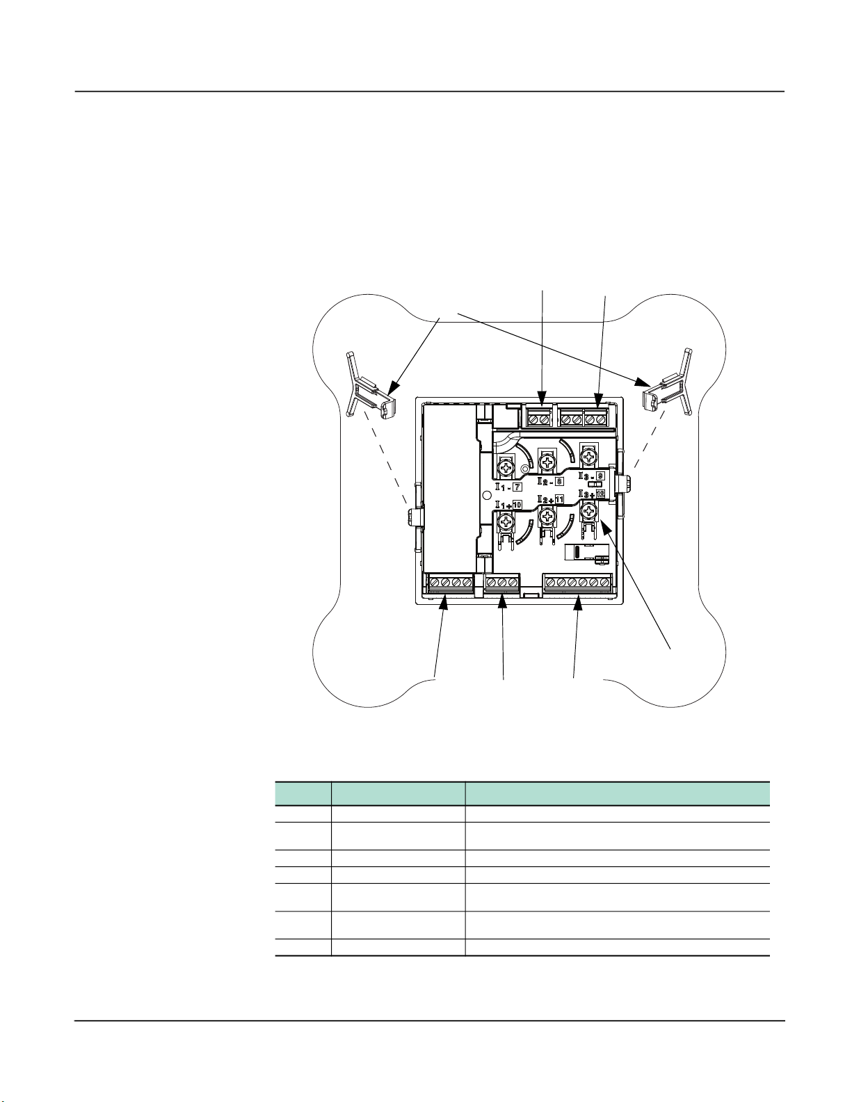
Figure 1– 1 below shows the parts of the power meter. Table 1– 1 describes the parts.
Figure 1– 1 Parts of the power meter (rear panel door removed)
B
C
A
G
D
E
F
Table 1– 1 Parts of the Power Meter
Number Part Description
A Retainer clips Used to secure the power meter in place
Control power supply
B
connector
C Voltage inputs Voltage metering connections
D Digital outputs Digital outputs (DO1 and DO2) connections
E RS-485 port (COM1)
F Digital inputs
G Current inputs Current metering connections
© 2021 Schneider Electric All Rights Reserved 1
Connection for control power to the power meter
Used for communications with a monitoring and control system, can
be daisy-chained to multiple devices
Digital inputs (DI1-DI4) connections, whetting voltage supplied by
power meter

PowerLogic™ Power Meter PM5350 63230-401-203A5
Chapter 1—Introduction 03/2021
Power Meter Parts and Accessories
Table 1– 2 Power Meter Models
Description Model Number
Power Meter with Integrated Display PowerLogic™ Power Meter PM5350
Box Contents
• One (1) power meter with retainer clips attached
• One (1) set of installation guides
• One (1) RS-485 Terminator (MCT2W)
• One (1) panel gasket
• One (1) certificate of calibration
• One (1) meter mounting template
• Three (3) screws (spare screws for CTs)
Firmware
This user guide is written to be used with firmware version 2.00.0000. See “Identifying the
Firmware Version, Model, and Serial Number” on page 61 for instructions on determining the
firmware version.
2 © 2021 Schneider Electric All Rights Reserved

63230-401-203A5 PowerLogic™ Power Meter PM5350
03/2021 Before You Begin
Chapter 2—Safety Precautions
Before You Begin
This section contains important safety precautions that must be followed before
attempting to install, service, or maintain electrical equipment. Carefully read and follow
the safety precautions outlined below.
HAZARD OF ELECTRIC SHOCK, EXPLOSION, OR ARC FLASH
• Apply appropriate personal protective equipment (PPE) and follow safe electrical
work practices. See NFPA 70E in the USA or applicable local standards.
• Only qualified electrical workers should install this equipment. Such work should be
performed only after reading this entire set of instructions.
• If the equipment is not used in a manner specified by the manufacturer, the protection
provided by the equipment may be impaired.
• NEVER work alone.
• Do not use this device for critical control or protection applications where human or
equipment safety relies on the operation of the control circuit.
• Before performing visual inspections, tests, or maintenance on this equipment, disconnect all sources of electric power. Assume that all circuits are live until they have
been completely de-energized, tested, and tagged. Pay particular attention to the design of the power system. Consider all sources of power, including the possibility of
backfeeding.
• Turn off all power supplying this device before working on it.
• Always use a properly rated voltage sensing device to confirm that all power is off.
• Do not exceed the device’s ratings for maximum limits.
• Before closing all covers and doors, carefully inspect the work area for tools and objects that may have been left inside the equipment.
• When removing or installing panels, do not allow them to extend into the energized
bus.
• The successful operation of this equipment depends upon proper handling, installation, and operation. Neglecting fundamental installation requirements may lead to personal injury as well as damage to electrical equipment or other property.
• NEVER bypass external fusing.
• NEVER short the secondary of a PT or VT.
• NEVER open circuit a CT; use the shorting block to short circuit the leads of the CT
before removing the connection from the power meter.
• Before performing Dielectric (Hi-Pot) or Megger testing on any equipment in which the
power meter is installed, disconnect all input and output wires to the power meter.
High voltage testing may damage electronic components contained in the demand
controller.
• This equipment should be installed in a suitable electrical enclosure.
• Always use grounded external CTs for current inputs.
• All external CT’s and PT’s should have reinforced insulation.
1. Turn off all power supplying this device before working on it.
2. Always use a properly rated voltage sensing device to confirm that all power is off.
© 2021 Schneider Electric. All Rights Reserved.
Failure to follow these instructions will result in death or serious injury.
3

PowerLogic™ Power Meter PM5350 63230-401-203A5
Before You Begin 03/2021
© 2021 Schneider Electric. All Rights Reserved.4
63230-401-203A5 PowerLogic™ Power Meter PM5350
6FUHHQ7LWOH
AB C
J
(GLW
FG
HI
D
E
L
K
03/2021 Operating the Display
Chapter 3—Operation
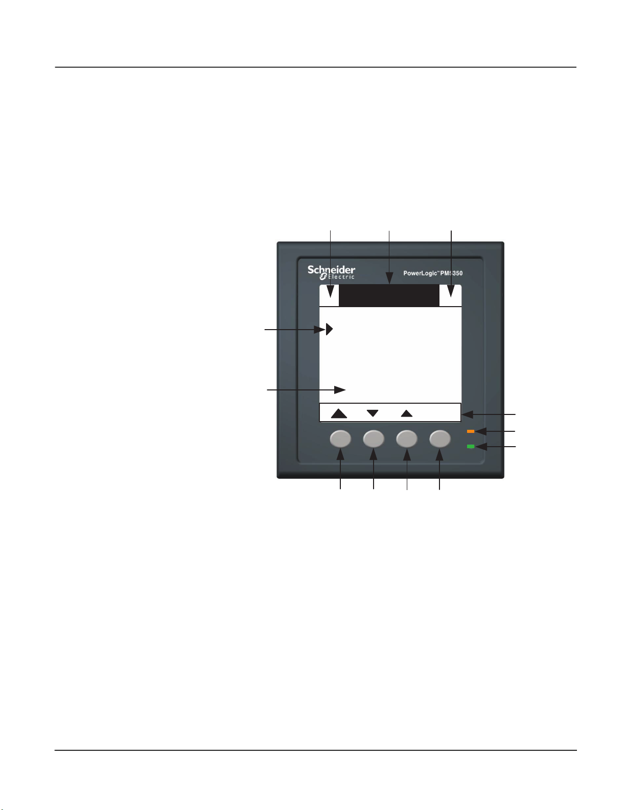
Operating the Display
The power meter is equipped with a large, back-lit LCD display. It is designed to display
up to six lines of information plus a row of menu options. Figure 3–1 shows the different
parts of the power meter display.
Figure 3–1: Power Meter Display
A. Icon 1—Wrench Icon (Maintenance) or Heartbeat Icon
B. Screen Title
C. Icon 2—Alarm Icon
D. Cursor
E. Data Area
F. Button 1
G. Button 2
H. Button 3
I. Button 4
J. Menu Area
K. Energy/Alarm LED (orange)
L. Heartbeat/Communication LED (green)
© 2021 Schneider Electric. All Rights Reserved.
5

PowerLogic™ Power Meter PM5350 63230-401-203A5
>
>
X
+
-
Operating the Display 03/2021
How the Buttons Work
The buttons select menu items, display more menu items in a menu list, and return to
previous menus. A menu item appears over one of the four buttons. Pressing a button
selects the menu item and displays the menu item’s screen. To return to the previous
menu level, press the button below
press the button below
Table 3–1: Button Symbols
Navigation
>
>
. Table 3–1 describes the button symbols.
Return to the previous screen. For setup screens:
• If setup changes are made, a confirmation screen is displayed.
• If editing a value, exits edit mode and restores previous value.
Move cursor down.
Move cursor up.
Move the cursor one character to the left.
▲. To cycle through the menu items in a menu list,
>
Edit
Select
OK
Yes
No
Ack
Reset
Detail
Next
Move cursor one character to the right.
Indicates the item is selected.
Increment active character; toggle list selection On.
Decrement active character; toggle list selection Off.
Select parameter or item to edit.
Select/deselect item for association.
Enter change to a parameter.
Accept.
Reject.
Acknowledge alarms.
Reset selected item.
Details of selected item.
Advance to next circuit reading (only available in Multi Circuit circuit mode.)
• To differentiate between menu items and parameters, menu items are placed in
brackets. For example, “[Phase]” denotes a phase menu item, and “Phase” denotes a
phase parameter.
• Each time you read “press” in this manual, press and release the appropriate button
beneath a menu item. For example, if you are asked to “Press [Phase],” you would
press and release the button below the phase menu item.
Changing Values
In this document, “item” refers to a feature such as an alarm, and “parameter” refers to an
attribute of an item such as a pickup setpoint.
© 2021 Schneider Electric. All Rights Reserved.6

63230-401-203A5 PowerLogic™ Power Meter PM5350
03/2021 Operating the Display
When you enter a setup screen, the cursor points to the first setup item or parameter on
the screen. Press
[Edit] to select a parameter. The value to be edited is displayed in the edit field, with the
active digit of the setup value shown in reverse video.
To change a text value:
▼ and ▲ to move to the item or parameter you wish to edit. Press
• Press to enter the selected value for the active digit and move to the next digit to
the right. At the maximum number of digits, the
takes you back to the first digit.
• Press + to increment and - to decrement the active digit through the numerals 0-9, the
letters A-Z, the “.” or any other possible selections.
To change a numerical value:
• Press to enter the selected value for the active digit and move to the next digit to
the left. At the maximum number of digits, the
takes you back to the first digit.
• Press + to increment the active digit through the numerals 0-9, and ".", "+", and "-".
To select a value from a list:
• Press + to scroll up and - to scroll down through the list of available selections.
• Press [OK] to enter the selected value.
Icons
LEDs
The icons flash to indicate the power meter LCD is operational.
• Wrench Icon—The power meter requires maintenance.
• Heartbeat Icon—The power meter LCD is operational.
• Alarm Icon—See “About Alarms” on page 39 and “Alarm Priorities” on page 41.
There are two LEDs on the power meter display, the energy/alarm LED and the
heartbeat/communication LED.
Energy/Alarm LED
Configure the energy/alarm LED in the following three ways:
• Energy Indicator—Flashes at a rate proportional to the amount of energy consumed,
allows the accuracy of the power meter to be verified.
• Alarm—Flashes as long as there are any active high priority alarms. The LED blinks
until the alarm is acknowledged.
• Off—Default
NOTE: See “Setting Up the Energy/Alarm LED” on page 60 for more information.
Heartbeat/Communication LED
The heartbeat/communication LED flashes at a steady rate during normal operation and
at a variable rate when communications is active.
NOTE: See “Heartbeat/Communication LED” on page 63 for more information.
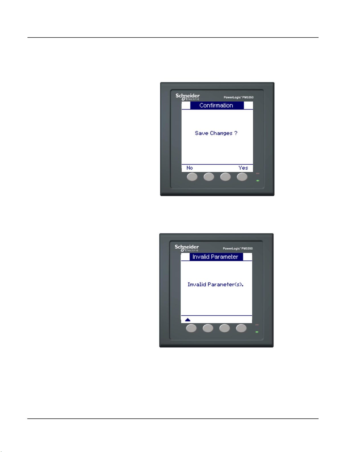
When you complete setup for the selected feature, press
screen. If any setup changes are made, a confirmation screen appears with the choice to
© 2021 Schneider Electric. All Rights Reserved.
▲ to return to the previous
7
PowerLogic™ Power Meter PM5350 63230-401-203A5
Operating the Display 03/2021
save the changes or cancel. Select [Yes], to save changes and return to the previous
screen. Select [No], to cancel the changes and return to the previous screen.
Figure 3–2: Confirmation screen
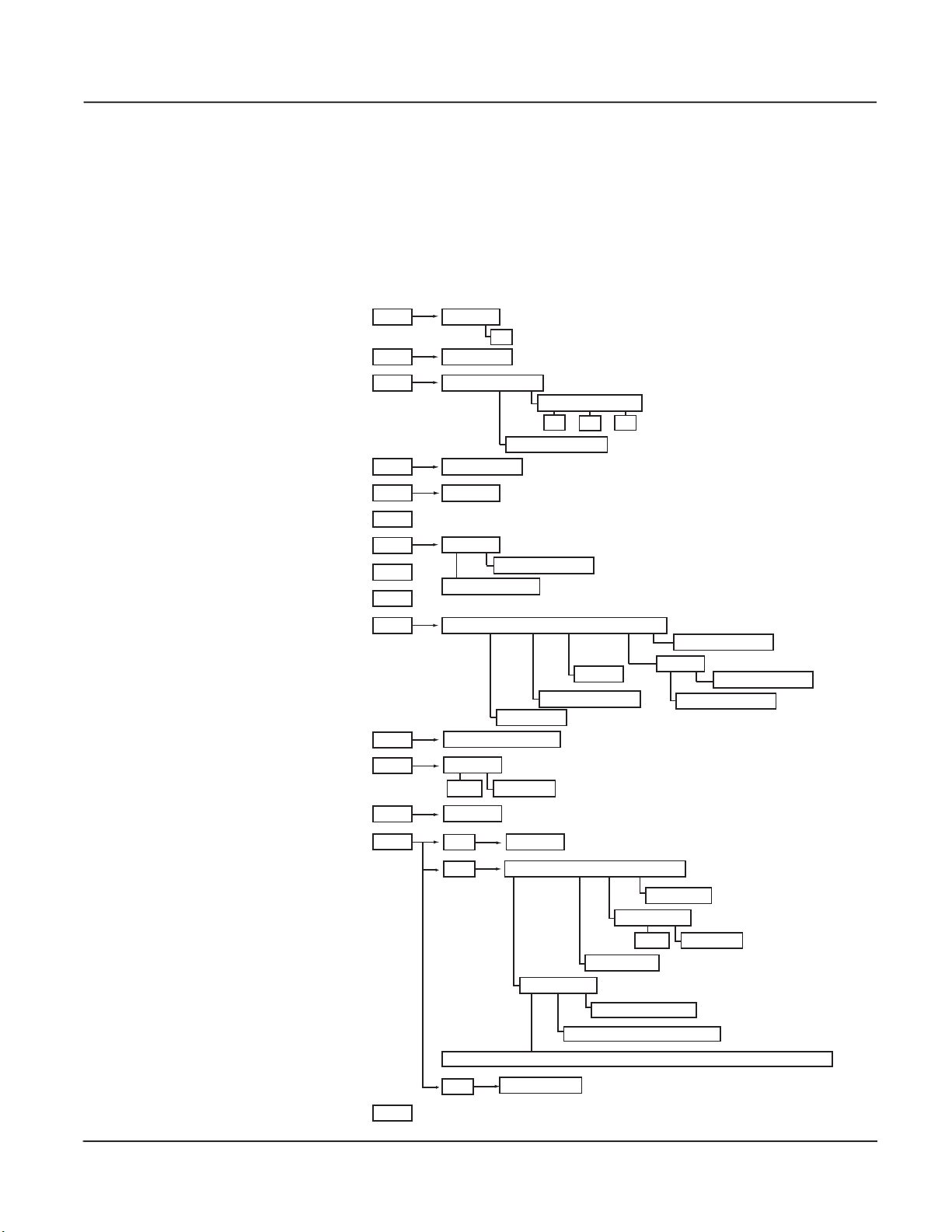
If any setup parameters are invalid, the “Invalid Parameter(s)” screen displays (see
Figure 3–3). Press
Figure 3–3: Invalid Parameter(s) screen
▲ to return to the previous setup screen.
© 2021 Schneider Electric. All Rights Reserved.8
63230-401-203A5 PowerLogic™ Power Meter PM5350
Phase Dmd
V L-L (U) V L-N (V)
Wh VAh VARh
Power (PQS) Phase Dmd
Amps (I) V L-L (U) V L-N (V)
Amps (I) Volts (U-V) Power (PQS) PF F (Hz) THD Unbal
Volts (U-V)
Power (PQS)
Energy (E)
PF
F (Hz)
THD
MnMx
Timer
Amps (I)
Wd (Pd) VARd (Qd) VAd (Sd)
Active (P) Reac (Q) Appr (S)
Pk DT
Pk DT
Pk DT
True Disp
LED D Out D In
Unbal
TDD
Amps (I) V L-L (U) V L-N (V)
THD thd
Alarm
I/O
Meter Comm Alarm I/O HMI Clock
Maint
Reset
Setup
Active Hist Count Unack
D Out D In
1-Sec Unary Dig
Basic Advan Dmd
Diag
Info Meter Cl Pwr
Disp Region Pass
Clock
V L-L (U) V L-N (V)
True Disp
THD thd
Pk DT
Load Oper
Level 1
Level 2
Global Single
Amps (I) V L-L (U) V L-N (V)
Amps (I) V L-L (U) V L-N (V)
Amps (I) V L-L (U) V L-N (V)
Active (P) Reac (Q) Appr (S)
DI1 DI2 DI3 DI4DO1 DO2
DI1 DI2 DI3 DI4
DO1 DO2
Power Demand Current Demand
Label Load Timer Setpt (A) PK I dmd for TDD (A)
Circuit Mode Power System VT Connect CT on Terminal CT Primary (A) CT Secondary (A) Sys Frequency (Hz) Phase Rotation
03/2021 Menu Overview
Menu Overview
Menu items are displayed below the horizontal line at the bottom of the screen. Figure 3–
4 below shows the menu items of the power meter menu hierarchy in Normal circuit
mode. Selecting a Level 1 menu item takes you to the next screen level containing the
Level 2 menu items. Some Level 2 items have Level 3 items. The navigation buttons work
consistently across all menu levels. Press
Figure 3–4: Menu Tree
to scroll through all menu items on a level.
© 2021 Schneider Electric. All Rights Reserved.
9

PowerLogic™ Power Meter PM5350 63230-401-203A5
Setting Up the Power Meter 03/2021
Setting Up the Power Meter
The power meter ships with many default values already set up. To change values,
navigate to the appropriate screen and enter new values. Use the instructions in the
following sections to change values. New values are automatically saved when you exit
the screen and accept the confirmation request.
Power Meter Basic Setup
To begin power meter basic setup:
1. Scroll to [Maint] in the menu list.
2. Press [Maint].
3. Press [Setup].
4. Enter your setup password.
NOTE: The default password is 0000. See “Setting Up Passwords” on page 24 for
information on changing passwords.
5. Press [Meter].
6. Press [Basic]. The Basic Setup screen appears.
Use the directions in the following sections to set up basic power meter values.
NOTE: If you make changes to the basic power meter setup, all alarms disable to prevent
undesired alarm operation. Confirm alarm configuration and enable the required alarms.
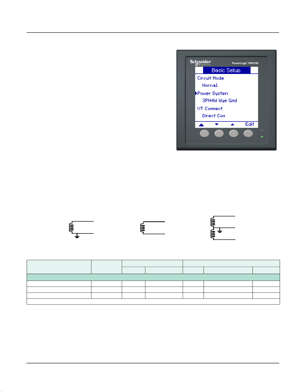
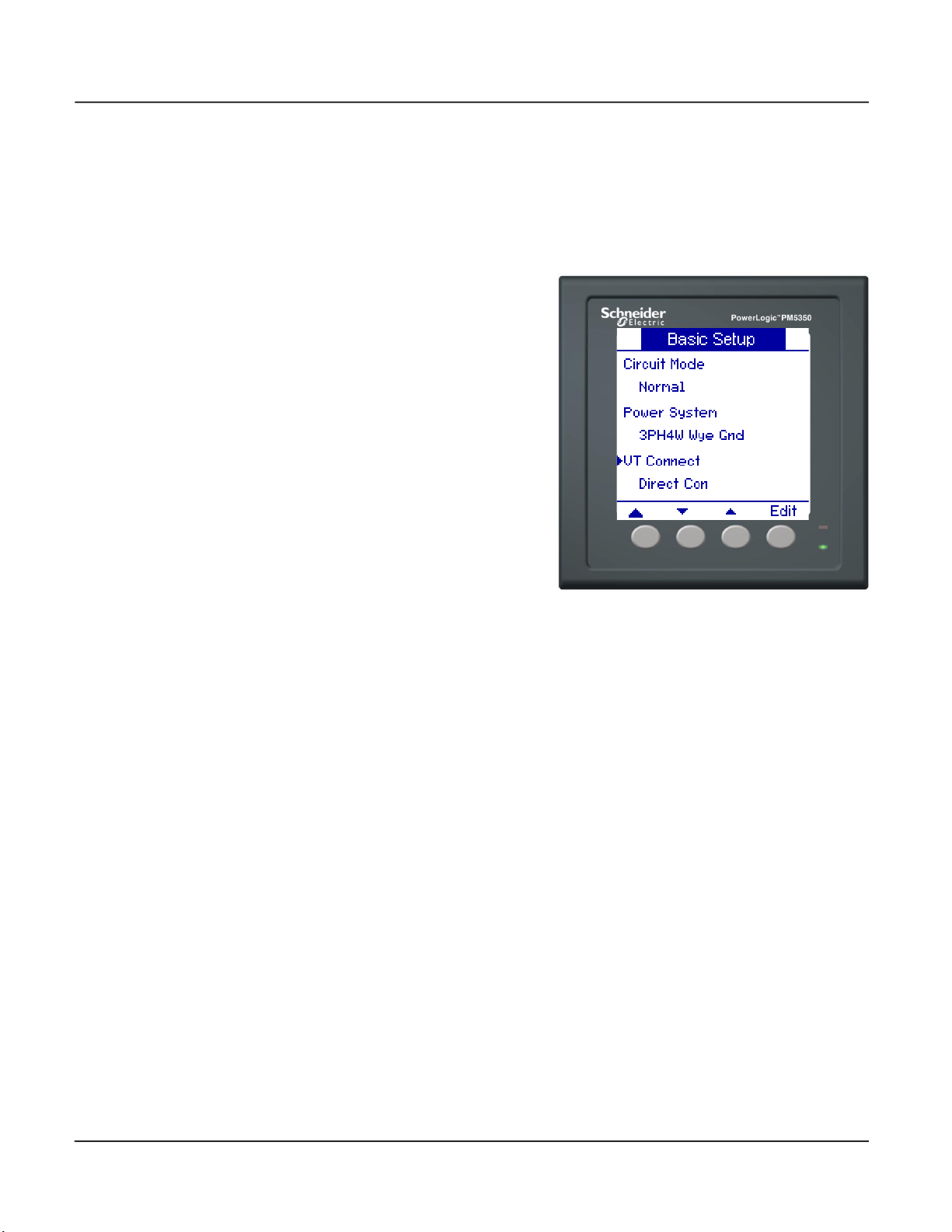
Setting Up the Power System
The power meter has two circuit modes: Normal (default) and Multi Circuit. See
“Supported Power System Configurations” on page 11 for more information on power
systems in Normal mode. See Appendix E on page 77 for information on multi circuit
power system configurations.
© 2021 Schneider Electric. All Rights Reserved.10
63230-401-203A5 PowerLogic™ Power Meter PM5350
03/2021 Power Meter Basic Setup
To set up the power system:
1. Press [Edit] to select Power
System.
2. Press + and - to scroll through
the list of supported power
system configurations.
3. Press [OK] to select the power
system configuration to be
metered.
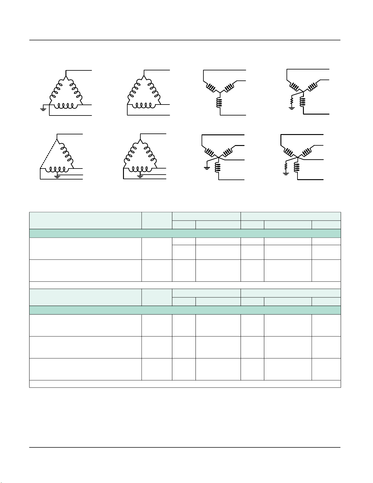
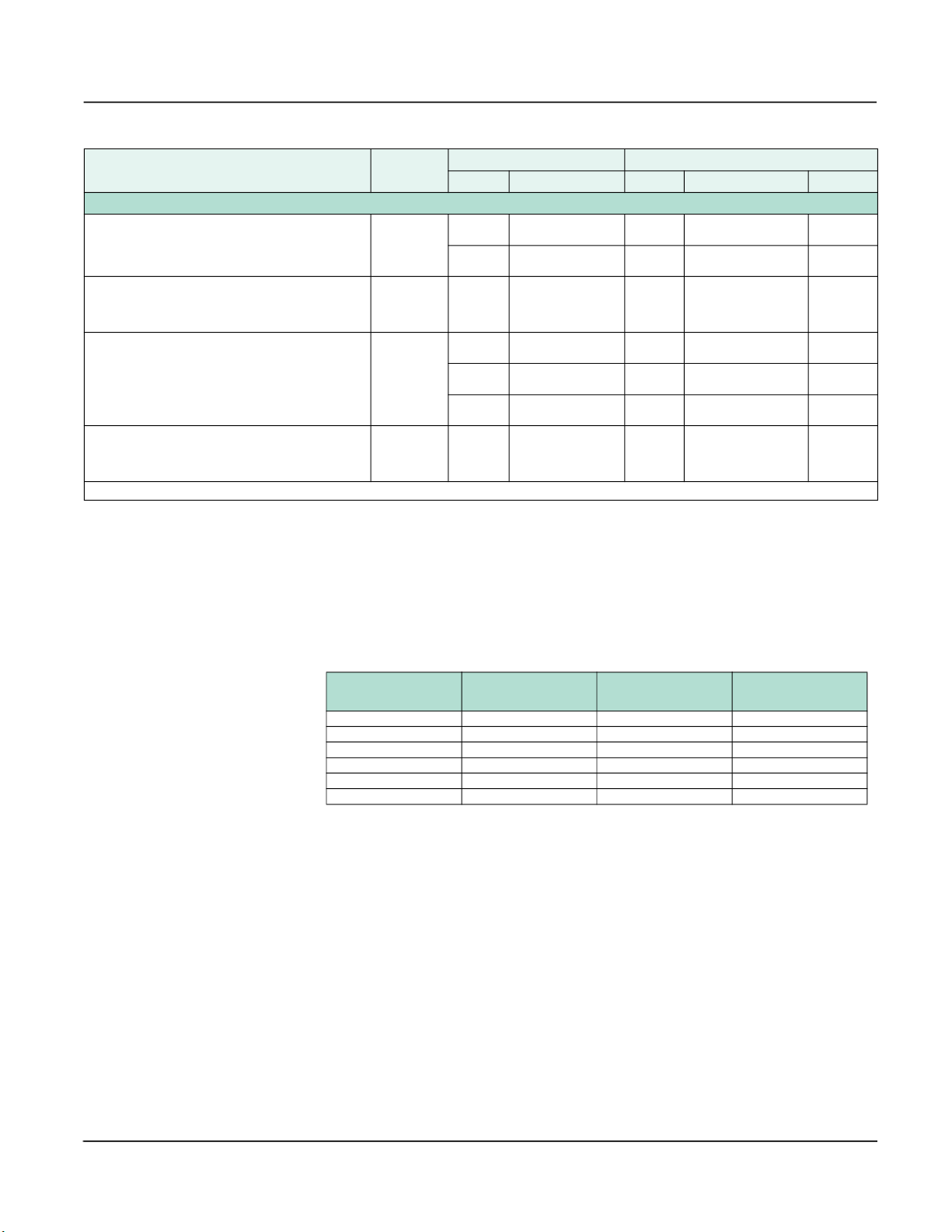
Supported Power System Configurations
The power meter supports several power system configurations. See Figure 3–5 and
Figure 3–6, and Table 3–2, Table 3–3, and Table 3–4 for details.
NOTE: There are additional supported power system configurations in Multi Circuit circuit
mode. See Appendix E on page 77 for information on multi circuit power system
configurations.
Figure 3–5: Single-Phase Power System Configurations
1PH2W LN
1PH2W LL
Table 3–2: Single-Phase
Power System Configuration
Number of
Wires
Qty. Meter Terminal Qty. Meter Terminal Type
CTs Voltage Connections
Single-Phase Wiring
1PH2W LN 2 1 I1 2 V1, Vn L-N
1PH2W LL 2 1 I1 2 V1, V2 L-L
1PH3W LL with N 3 2 I1, I2 3 V1, V2, Vn L-L with N
NOTE: For 1 CT and 2 CT systems, you must configure the power meter for the phase on which the CT is installed.
1PH3W LL with N
© 2021 Schneider Electric. All Rights Reserved.
11
PowerLogic™ Power Meter PM5350 63230-401-203A5
N
N
N
N
Power Meter Basic Setup 03/2021
Figure 3–6: Three-Phase Power System Configurations
3PH3W Delta Corner Grounded
(3PH3W Dlt Crnr Gnd)
3PH4W Open Delta Center-Tapped
(3PH4W Opn Dlt Ctr Tp)
3PH3W Delta Ungrounded
(3PH3W Dlt Ungnd)
3PH4W Delta Center-Tapped
(3PH4W Dlt Ctr Tp)
3PH3W Wye Ungrounded
(3PH3W Wye Ungnd)
3PH4W Wye Grounded
(3PH4W Wye Gnd)
Table 3–3: Three-Phase Direct Connect
Power System Configuration
Number of
Wires
Qty. Meter Terminal Qty. Meter Terminal Type
CTs Voltage Connections
Three-Phase Wiring
3PH3W Dlt Crnr Gnd
3PH3WDlt Ungnd
3PH3W Wye Ungnd
3PH3W Wye Res Gnd
3PH3W Dlt Crnr Gnd
3PH3WDlt Ungnd
3PH3W Wye Ungnd
3PH3W Wye Res Gnd
NOTE: For 1 CT and 2 CT systems, you must configure the power meter for the phase on which the CT is installed.
Power System Configuration
3
3 1 I1 3 V1, V2, V3
Number of
Wires
2 I1, I3 3 V1, V2, V3 Delta
3 I1, I2, I3 3 V1, V2, V3 Delta
CTs Voltage Connections
Qty. Meter Terminal Qty. Meter Terminal Type
Three-Phase Wiring
3PH4W Opn Dlt Ctr Tp
3PH4W Dlt Ctr Tp
3PH4W Wye Gnd
3PH4W Wye Res Gnd
3PH4W Opn Dlt Ctr Tp
3PH4W Dlt Ctr Tp
3PH4W Wye Gnd
3PH4W Wye Res Gnd
3PH4W Opn Dlt Ctr Tp
3PH4W Dlt Ctr Tp
3PH4W Wye Gnd
3PH4W Wye Res Gnd
NOTE: For 1 CT and 2 CT systems, you must configure the power meter for the phase on which the CT is installed.
4 3 I1, I2, I3 4 V1, V2, V3, Vn Delta
4 3 I1, I2, I3 4 V1, V2, V3, Vn Wye
4 1 I1 4 V1, V2, V3, Vn
3PH3W Wye Resistance Grounded
(3PH3W Wye Res Gnd)
3PH4W Wye Resistance Grounded
(3PH4W Wye Res Gnd)
Delta
(Balanced)
Wye
(Balanced)
© 2021 Schneider Electric. All Rights Reserved.12
63230-401-203A5 PowerLogic™ Power Meter PM5350
03/2021 Power Meter Basic Setup
Table 3–4: Three-Phase (with VTs)
Power System Configuration
Number of
Wires
Qty. Meter Terminal Qty. Meter Terminal Type
CTs Voltage Connections
Three-Phase Wiring
3PH3W Dlt Crnr Gnd
3PH3WDlt Ungnd
3PH3W Wye Ungnd
3PH3W Wye Res Gnd
3PH3W Dlt Crnr Gnd
3PH3WDlt Ungnd
3PH3W Wye Ungnd
3PH3W Wye Res Gnd
3PH4W Opn Dlt Ctr Tp
3PH4W Dlt Ctr Tp
3PH4W Wye Gnd
3PH4W Wye Res Gnd
3PH4W Opn Dlt Ctr Tp
3PH4W Dlt Ctr Tp
3PH4W Wye Gnd
3PH4W Wye Res Gnd
NOTE: For 1 CT and 2 CT systems, you must configure the power meter for the phase on which the CT is installed.
3
3 1 I1 2
4
4 1 I1 3
2 I1, I3 2
3 I1, I2, I3 2
3 I1, I2, I3 3
3 I1, I2, I3 2
2 I1, I2, I3 3
Overcurrent Protection
Clearly label the device’s disconnect circuit mechanism and install it within easy reach of
the operator.
V1, V3
(V2 to Ground)
V1, V3
(V2 to Ground)
V1, V3
(V2 to Ground)
V1, V2, V3
(Vn to Ground)
V1, V3
(Vn to Ground)
V1, V2, V3
(Vn to Ground)
V1, V2, V3
(Vn to Ground)
Delta
Delta
Delta
(Balanced)
Wye
Wye
Wye
Wye
(Balanced)
NOTE: The disconnect circuit breaker or fusing must be rated for the available short
circuit current at the connection points.
Table 3–1: Fuse Recommendations
Control Power
Source
CPT Vs ≤ 125 Vac FNM or MDL 250 mA
CPT 125 < V
CPT 240 < V
Line Voltage V
Line Voltage V
DC V
Source Voltage (Vs) Fuse Fuse Amperage
≤ 240 Vac FNQ or FNQ-R 250 mA
s
≤ 277 Vac FNQ or FNQ-R 250 mA
s
≤ 240 Vac FNQ-R 250 mA
s
> 240 Vac FNQ-R 250 mA
s
≤ 300 Vdc LP-CC 500 mA
s
For selecting fuses and circuit breakers other than those listed above, use the following
criteria:
• Select overcurrent protection rated as listed above.
• Select current interrupt capacity based on the installation category and fault current
capability.
• Select overcurrent protection with a time delay.
• The voltage rating should be based on the input voltage applied.
• If a 250 mA fuse is not available with the required fault current capability, use a fuse
rated at a maximum of 500 mA.
• Fuse protection can be substituted with molded-case circuit breaker 0.5A/4-Pole.
© 2021 Schneider Electric. All Rights Reserved.
13
PowerLogic™ Power Meter PM5350 63230-401-203A5
Power Meter Basic Setup 03/2021
Setting Up Voltage Connection and CT Options
The options available for voltage connections (VT Connect) and the number of CTs that
can be selected (CT on Terminal) are based on the power system selected in “Setting Up
the Power System” on page 10. The CT Primary and Secondary are set in Amps (A).
To set up voltage connections and CTs:
1. Press
2. Press + and - to scroll through the
3. Press [OK] to select the VT
4. Press
5. Press + and - to scroll through the
6. Press [OK] to select VT Primary
7. Press
8. Press
9. Press + and - to scroll through the
10. Press [OK] to enter the terminal
11. Press
12. Press + to increment the active
13. Press
14. Continue until all values are
15. Press
16. Press + and - to scroll through a
17. Press [OK] to select the CT
▼ to select VT Connect,
then press [Edit].
VT Connect options.
Connect. If you choose Direct Con,
skip to step 8.
▼ to select VT Primary (V),
then press [Edit].
options.
(V).
▼ to select VT Secondary
(V), then follow steps 4 to 6 to
select VT Secondary.
▼ to select CT on
Terminal, then press [Edit].
terminal options.
the CT is on.
▼ to select CT Primary (A),
then press [Edit].
digit through the numerals 0-9.
to enter the selected
value for the active digit and move
to the next digit to the left.
selected, then press [OK] to enter
the CT Primary.
▼ to select CT Secondary
(A), then press [Edit].
list of CT Secondary options.
NOTE: CT Secondary options are
5A or 1A. See “Specifications” on
page 65 for accuracy level.
Secondary.
© 2021 Schneider Electric. All Rights Reserved.14
63230-401-203A5 PowerLogic™ Power Meter PM5350
03/2021 Power Meter Basic Setup
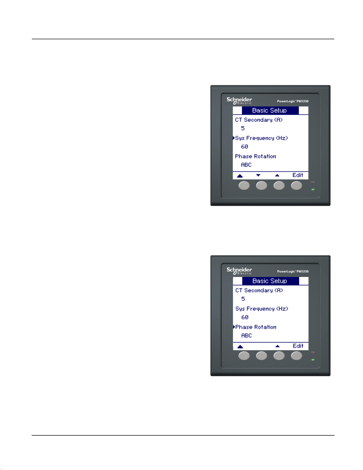
Setting Up the System Frequency
The system frequency is limited to 50 Hz or 60 Hz.
To set up the system frequency:
1. Press
2. Press + and - to scroll between
3. Press [OK] to select the system
Setting Up the Phase Rotation
The phase rotation is limited to ABC or CBA.
To set up the phase rotation:
1. Press ▼ to select Phase
2. Press + and - to scroll between
3. Press [OK] to select the phase
▼ to select System
Frequency, then press [Edit].
50 and 60 Hz.
frequency.
Rotation, then press [Edit].
ABC and CBA.
rotation.
© 2021 Schneider Electric. All Rights Reserved.
15

PowerLogic™ Power Meter PM5350 63230-401-203A5
Power Meter Advanced Setup 03/2021
Power Meter Advanced Setup
To begin power meter advanced setup:
1. Scroll to [Maint] in the menu list.
2. Press [Maint].
3. Press [Setup].
4. Enter your setup password.
NOTE: The default password is 0000. See “Setting Up Passwords” on page 24 for
information on changing passwords.
5. Press [Meter].
6. Press [Advan].
Use the directions in the following sections to set up power meter advanced values.
Setting Up the Load Timer Setpoint
There are two typical uses for the load timer setpoint:
• Select a relatively low setpoint. The timer increments when the load being metered is
running. This could be useful in recording machine run time for a preventive
maintenance program.
• Select a setpoint that is equal to the rating of the power system conductors. The timer
increments and records how long the conductors were overloaded. This could be
used to help determine if a circuit has the capacity to add additional load or if loads
should be moved to another circuit.
The load timer setpoint is set in Amps (A).
To set up the load timer setpoint:
1. Press
2. Press + to increment the active
3. Press
4. Continue until all values are
▼ to select Load Timer
Setpoint, then press [Edit].
digit through the numerals 0-9.
to enter the selected
value for the active digit and
move to the next digit to the left.
selected, then press [OK] to set
the load timer setpoint.
© 2021 Schneider Electric. All Rights Reserved.16

63230-401-203A5 PowerLogic™ Power Meter PM5350
03/2021 Power Meter Demand Setup
Setting Up the Peak Current Demand Over Last Year
The peak current demand over last year calculates Total Demand Distortion (TDD) in
amperes. See the TDD discussion in “Power Analysis Values” on page 37 for more
information. Enter 0 if you want the power meter to use metered current peak demand for
this calculation.
The peak current demand is set in Amps (A).
To set up the peak current demand over last year:
1. Press
Dmd for TDD, then press [Edit].
2. Press + to increment the active
digit through the numerals 0-9.
3. Press
value for the active digit and
move to the next digit to the left.
4. Continue until all values are
selected, then press [OK] to
enter the peak current demand
over last year.
Power Meter Demand Setup
To begin power meter demand setup:
1. Scroll to [Maint] in the menu list.
2. Press [Maint].
3. Press [Setup].
4. Enter your setup password.
NOTE: The default password is 0000. See “Setting Up Passwords” on page 24 for
information on changing passwords.
5. Press [Meter].
6. Press [Dmd].
▼ to select Pk Current
to enter the selected
Use the directions in the following sections to set up power meter demand values.
© 2021 Schneider Electric. All Rights Reserved.
17
PowerLogic™ Power Meter PM5350 63230-401-203A5
Power Meter Demand Setup 03/2021
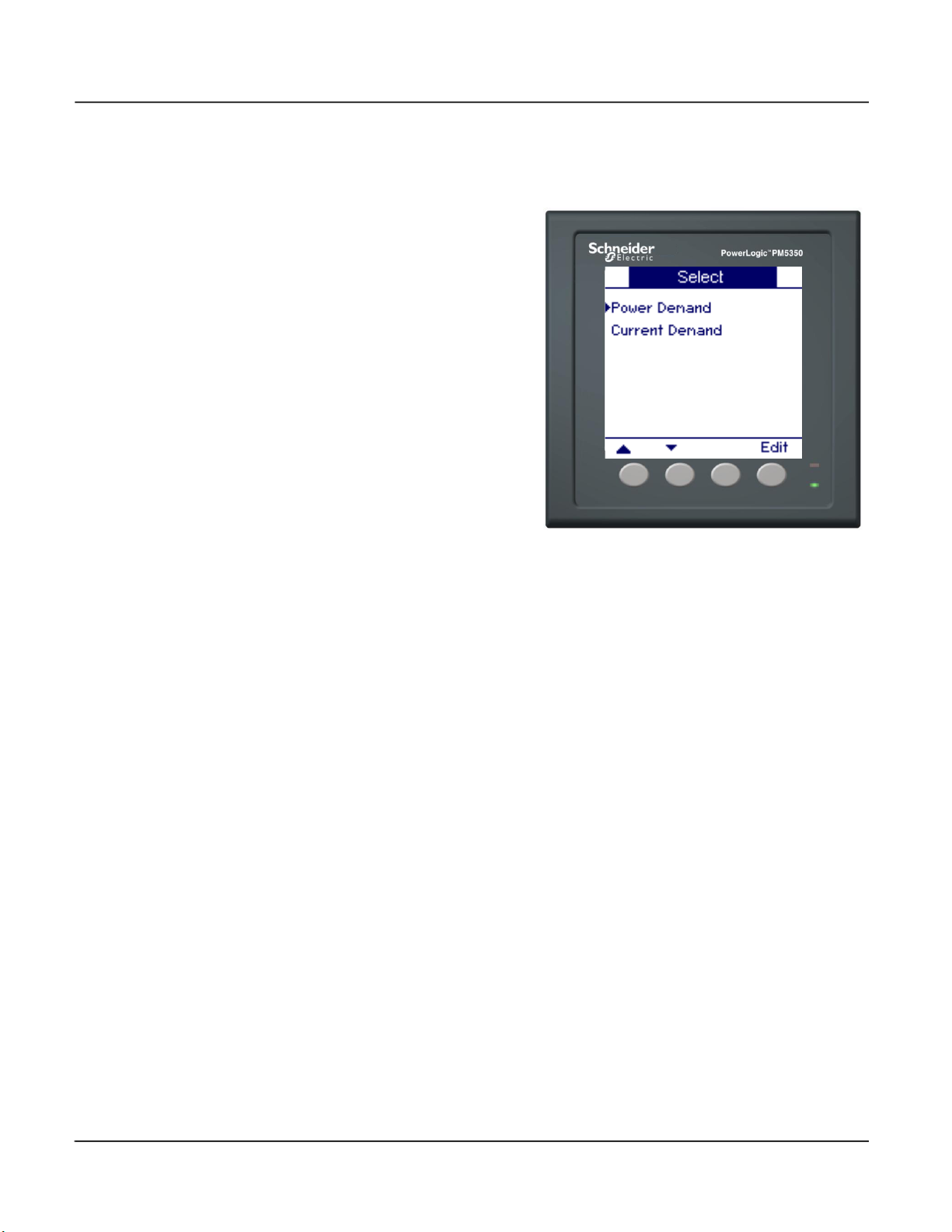
Setting Up Power and Current Demand
To set up the power or current, demand:
1. Press
2. Press [Edit] to select a demand.
3. Press [Edit] to select Method.
4. Press + and - to scroll through a
5. Press [OK] to select the
6. Press
7. Press + to increment the active
8. Press
9. Continue until all values are
10. If you selected a Rolling Block
11. Press + to increment the active
12. Continue until all values are
▼ and ▲ to scroll
between Power and Current
Demand.
list of supported demand
methods.
demand method.
NOTE: If you select Input Sync
Block or Rolling Block, see
“Select the Digital Input” on
page 19.
▼ to select Interval,
then press [Edit].
digit through the numerals 0-9.
to enter the selected
number for the active digit and
move to the next digit to the left.
selected, then press [OK] to
enter the interval.
method (Timed, Input Sync,
Cmd Sync), press
Subinterval, then press [Edit].
Otherwise, proceed to Step 13.
digit through the numerals 0-9.
NOTE: The subinterval duration
must be evenly divisible into the
demand interval duration.
selected, then press [OK] to
enter the subinterval.
▼ to select
© 2021 Schneider Electric. All Rights Reserved.18
63230-401-203A5 PowerLogic™ Power Meter PM5350
03/2021 Power Meter Demand Setup
Setting Up Power and Current Demand (continued)
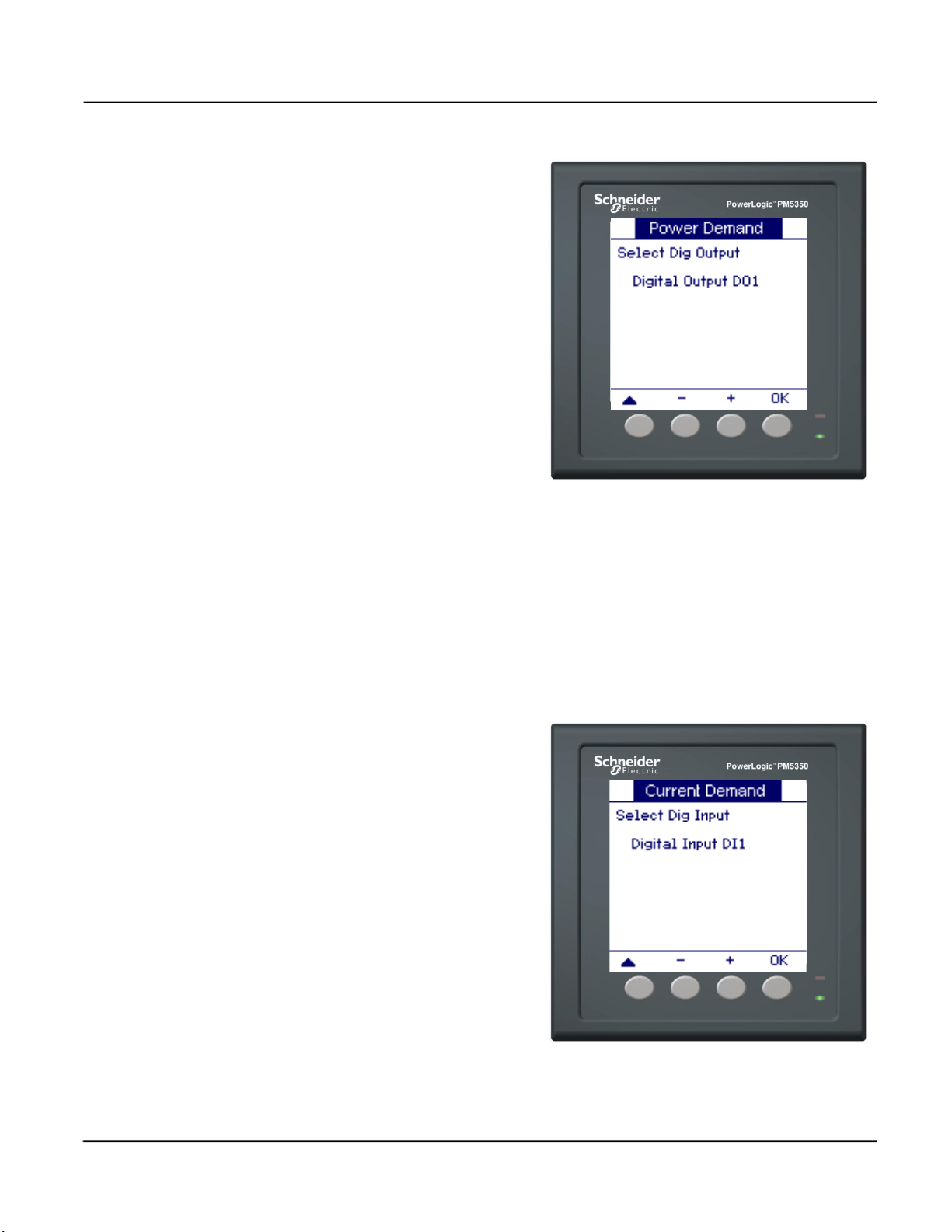
Select the Digital Input
13. Press
14. Press + and - to scroll through
15. Press [OK] to select the digital
16. Press
If you select Input Sync Block or Input Sync Rolling Block as the demand method, select
the digital input to be associated with the demand system.
▼to select Select Dig
Output, then press [Edit].
the digital outputs.
output to be associated with the
demand system.
▲ to return to the
previous screen.
NOTE: If existing associations
will be lost by making the new
selection, a confirmation screen
appears.
— Press [Yes] to accept the
changes and return to the
previous screen.
— Press [No] to keep the
existing configuration and
return to the previous
screen.
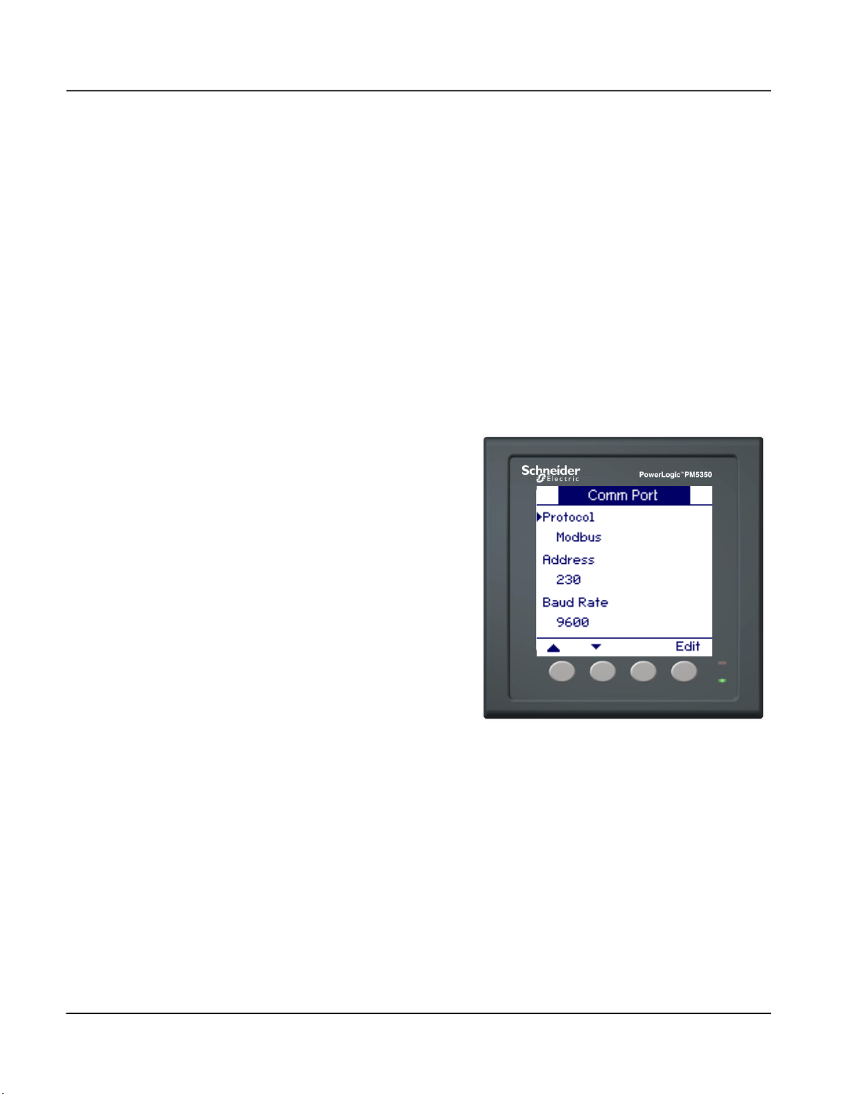
When the digital input is energized, the demand interval will trigger. For a valid demand
interval, the digital input must be energized within +/-5 seconds of the set interval.
To select the digital input:
1. Press ▼to select Select Dig
Input, then press [Edit].
2. Press + and - to scroll through
the digital inputs.
3. Press [OK] to select the digital
input to be associated with the
demand system.
4. Press
▲ to return to the
previous screen.
NOTE: If existing associations
will be lost by making the new
selection, a confirmation screen
appears.
— Press [Yes] to accept the
changes and return to the
previous screen.
— Press [No] to keep the
existing configuration and
return to the previous
screen.
© 2021 Schneider Electric. All Rights Reserved.
19
PowerLogic™ Power Meter PM5350 63230-401-203A5
Power Meter Communication Setup 03/2021
Power Meter Communication Setup
To begin power meter communication setup:
1. Scroll to [Maint] in the menu list.
2. Press [Maint].
3. Press [Setup].
4. Enter your setup password.
NOTE: The default password is 0000. See “Setting Up Passwords” on page 24 for
information on changing passwords.
5. Press [Comm]. The Communication Setup screen appears.
Use the directions in the following sections to set up power meter communications values.
Setting Up Communications
To set up communications:
1. Press
2. Press + and - to scroll through
3. Press [OK] to set the protocol.
4. Press
5. Press + to increment the active
6. Press
7. Continue until all values are
8. Press
9. Press + and - to scroll through
10. Press [OK] to set the Baud rate.
11. Press
12. Press + and - to scroll through
13. Press [OK] to set the parity.
▼ to select Protocol,
then press [Edit].
the protocol options.
▼ to select Address,
then press [Edit].
digit through the numerals 0-9.
to enter the selected
value for the active digit and
move to the next digit to the left.
selected, then press [OK] to set
the address.
▼ to select Baud Rate,
then press [Edit].
the Baud rate options.
▼ to select Parity, then
press [Edit].
the parity options.
Setting Up Alarms
See “Alarms” on page 39 for information on setting up alarms.
© 2021 Schneider Electric. All Rights Reserved.20
63230-401-203A5 PowerLogic™ Power Meter PM5350
03/2021 Power Meter HMI Setup
Setting Up I/O
See “Input/Output Capabilities” on page 51 for information on setting up I/O.
Power Meter HMI Setup
To begin power meter HMI setup:
1. Scroll to [Maint] in the menu list.
2. Press [Maint].
3. Press [Setup].
4. Enter your setup password.
NOTE: The default password is 0000. See “Setting Up Passwords” on page 24 for
information on changing passwords.
5. Press [HMI]. The HMI Setup screen appears.
Use the directions in the following sections to set up power meter HMI values.
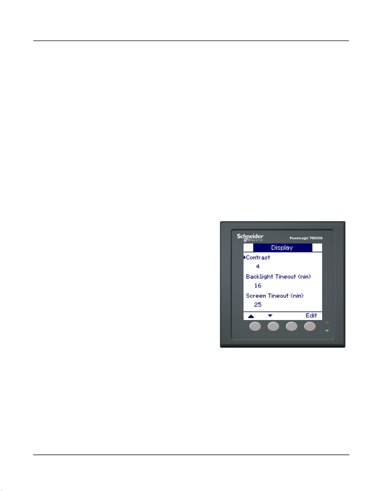
Setting Up the Display
To set up the display:
1. Press [Disp]. The Display
screen appears.
2. Press [Edit] to select Contrast.
3. Press + to increment the active
digit through the numerals 0-9.
NOTE: The contrast values
range between 1 and 9.
4. Press [OK] to set the contrast.
5. Press
6. Press + to increment the active
7. Press
8. Continue until all values are
▼to select Backlight
Timeout (min), then press
[Edit].
digit through the numerals 0-9.
NOTE: The backlight timeout
values range between 0 and 60
minutes. 0 disables the timeout.
to enter the selected
value for the active digit and
move to the next digit to the left.
selected, then press [OK] to set
the backlight timeout.
© 2021 Schneider Electric. All Rights Reserved.
21
PowerLogic™ Power Meter PM5350 63230-401-203A5
Power Meter HMI Setup 03/2021
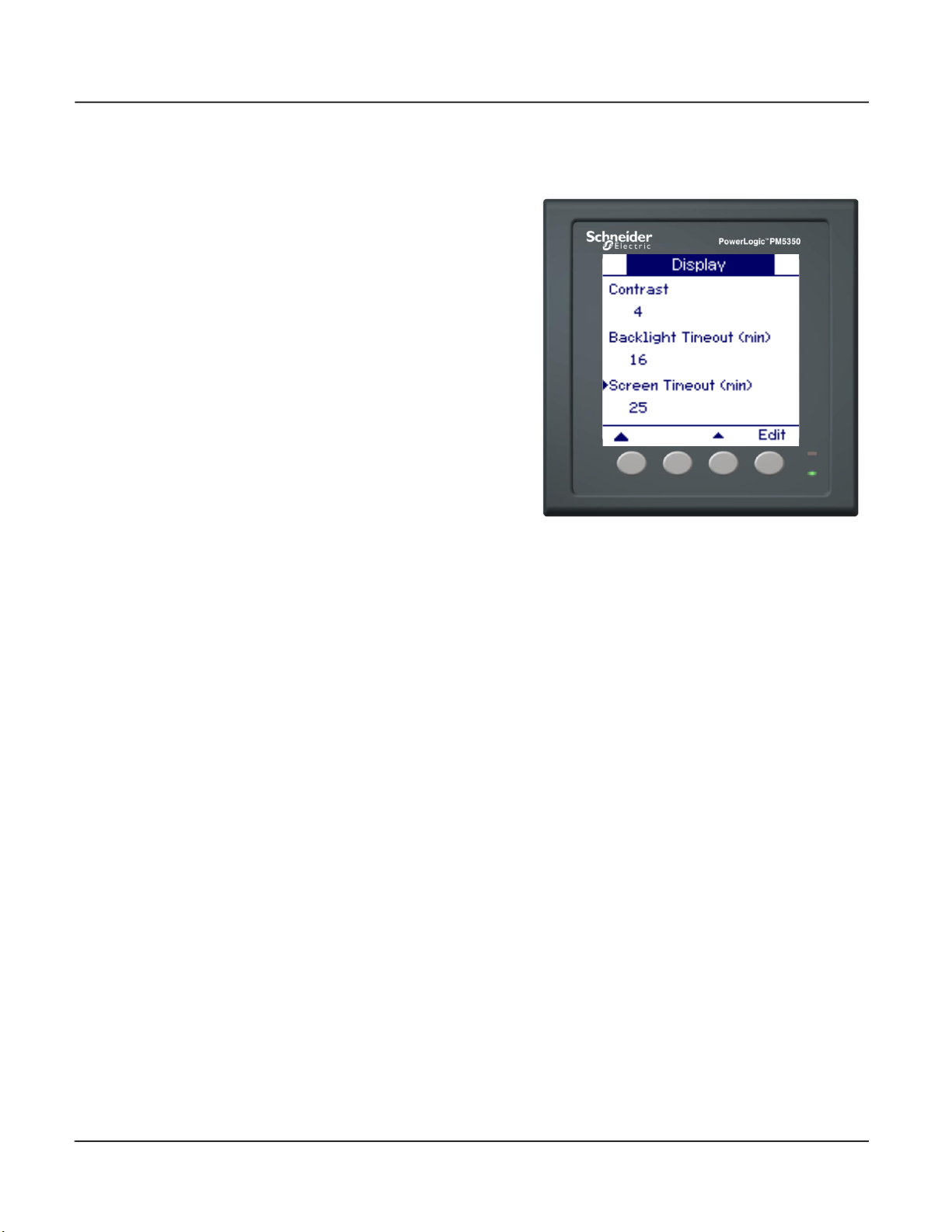
Setting Up the Display (continued)
9. Press ▼to select Screen
Timeout (min), then press
[Edit].
10. Press + to increment the active
digit through the numerals 0-9.
NOTE: The screen timeout
values range between 0 and 60
minutes. 0 disables the timeout.
11. Press
12. Continue until all values are
13. Press
to enter the selected
value for the active digit and
move to the next digit to the left.
selected, then press [OK] to set
the screen timeout.
▲ to return to the
previous screen.
NOTE: If existing associations
will be lost by making the new
selection, a confirmation screen
appears.
— Press [Yes] to accept the
changes and return to the
previous screen.
— Press [No] to keep the
existing configuration and
return to the previous
screen.
© 2021 Schneider Electric. All Rights Reserved.22

63230-401-203A5 PowerLogic™ Power Meter PM5350
03/2021 Power Meter HMI Setup
Setting Up Regional Settings
To set up regional settings:
1. Press [Region]. The Regional
Settings screen appears.
2. Press [Edit] to select Language.
3. Press + and - to scroll through
the language options.
4. Press [OK] to set the language.
NOTE: Models with
communications support the
download of language files with
additional languages to the
power meter. All languages
available on the power meter
are listed. See “Downloading
Firmware” on page 62 for more
information.
5. Press
6. Press + and - to scroll through
7. Press [OK] to set the date
8. Press
9. Press + and - to scroll through
10. Press [OK] to set the time
11. Press
12. Press + and - to scroll through
13. Press [OK] to set the HMI
14. Press
▼to select Date Format,
then press [Edit].
the date format options.
format.
▼to select Time
Format, then press [Edit].
the time format options.
format.
▼to select HMI Mode,
then press [Edit].
the HMI mode options.
mode.
▲ to return to the
previous screen.
NOTE: If existing associations
will be lost by making the new
selection, a confirmation screen
appears.
— Press [Yes] to accept the
changes and return to the
previous screen.
— Press [No] to keep the
existing configuration and
return to the previous
screen.
© 2021 Schneider Electric. All Rights Reserved.
23

PowerLogic™ Power Meter PM5350 63230-401-203A5
Power Meter Clock Setup 03/2021
Setting Up Passwords
The passwords for HMI access to setup and resets are configurable. Passwords must use
four numeric characters. The characters are from the US ASCII character set and are not
translated or affected by language selection.
To set up a password:
1. Press
2. Press [Edit] to select a
3. Press + to increment the active
4. Press
5. Continue until all values are
Power Meter Clock Setup
To begin power meter clock setup:
1. Scroll to [Maint] in the menu list.
2. Press [Maint].
3. Press [Setup].
4. Enter your setup password.
5. Press [Clock]. The Clock setup screen appears.
▼ and ▲ to scroll
through the passwords in the
Passwords screen.
password.
digit through the numerals 0-9.
to enter the selected
value for the active digit and
move to the next digit to the left.
selected, then press [OK] to set
the password.
NOTE: The default password is 0000. See “Setting Up Passwords” on page 24 for
information on changing passwords.
Use the directions in the following sections to set up power meter clock values.
© 2021 Schneider Electric. All Rights Reserved.24

63230-401-203A5 PowerLogic™ Power Meter PM5350
03/2021 Reset the Power Meter
Setting Up the Clock
The power meter stores all date and time stamps in GMT. If “Local” meter time is
selected, the GMT offset converts the GMT values to local date and time values for
display on the HMI. There is also an option to display the GMT values on the HMI.
To set up the clock:
1. Press [Edit] to select Date.
2. Press + to increment the active
digit for the first character of the
date.
3. Press
4. Continue until all values are
5. Press
6. Press
7. Press + and - to scroll through
8. Press [OK] to set the meter
to enter the selected
character and move to the
character to the left.
selected, then press [OK] to set
the date.
▼and follow Steps 2 to
6 to set the Time.
▼to select Meter Time,
then press [Edit].
the meter time options.
time.
Reset the Power Meter
To begin power meter reset setup:
1. Scroll to [Maint] in the menu list.
2. Press [Maint].
3. Press [Reset]. The Resets screen appears.
Meter values can be re-initialized using the reset function. Resets are grouped into global
resets and single resets. Use the directions in the following sections to set up power
meter reset values.
© 2021 Schneider Electric. All Rights Reserved.
25

PowerLogic™ Power Meter PM5350 63230-401-203A5
Reset the Power Meter 03/2021
Global Resets
Global resets include power meter reinitialization, as well as resets of all values for the
following items:
• Energies
• Demands
• Min/Max Values
• Alarm Logs and Counters
• I/O Counters and Timers
To reinitialize the power meter:
1. Press [Select] to select Global
Resets.
2. Press [Reset] to select Meter
Initialization.
3. Enter the Energy Password,
then press [OK].
4. A confirmation screen appears.
— Press [Yes] to reset the
power meter.
— Press [No] to return to the
previous screen.
To reset all values for a selected
item:
1. Press [Select] to select Global
Resets.
2. Press
3. Press [Reset].
4. Press [OK].
5. A confirmation screen appears.
▼ and ▲ to scroll to
the item you want to reset.
NOTE: If you selected
energies, demands, or
min/max, a password is
required. Enter the reset
password for the selected item.
— Press [Yes] to reset all
values.
— Press [No] to return to the
previous screen.
© 2021 Schneider Electric. All Rights Reserved.26

63230-401-203A5 PowerLogic™ Power Meter PM5350
03/2021 Reset the Power Meter
Single Resets
Single resets allow you to reset specific items individually. Use the single reset option to
reset he following values:
• Energy
• Demand
• Alarms
• Digital Inputs
• Digital Outputs
• Active Load Timer
To reset a value for the selected item:
1. Press
2. Press
3. Press [Select].
4. In the item Reset screen, press
▼to select Single
Resets, then press [Select].
▼ and ▲ to scroll to
the item you want to reset.
NOTE: If you selected energy
or demand, a password is
required. Enter the reset
password for the selected item.
▼ and ▲ to select the
specific value you wish to reset.
NOTE: The example displays a
demand reset with Demand
selected for reset.
5. Press [Reset] to reset the
selected value.
6. A confirmation screen appears.
— Press [Yes] to reset the
selected value.
— Press [No] to return to the
previous screen.
© 2021 Schneider Electric. All Rights Reserved.
27

PowerLogic™ Power Meter PM5350 63230-401-203A5
Reset the Power Meter 03/2021
© 2021 Schneider Electric. All Rights Reserved.28

63230-401-203A5 PowerLogic™ Power Meter PM5350
03/2021 Power Meter Characteristics
Chapter 4—Metering
Power Meter Characteristics
The power meter measures currents and voltages and reports in real time the rms values
for all three phases and neutral. In addition, the power meter calculates power factor, real
power, reactive power, and more.
The PM5350 is not for use on Direct Current (DC) circuits. The power meter will
incorrectly read 0 volts.
Table 4–1 lists metering characteristics of the power meter.
Table 4–1: Power Meter Characteristics
Instantaneous rms Values
Current Per phase, neutral or ground, average of 3 phases
Voltage Average of 3 phases, L-L and L-N
Frequency 45 to 70 Hz
Active power Total and per phase (signed)
Reactive power Total and per phase (signed)
Apparent power Total and per phase
True Power Factor Total and per phase 0.000 to 1 (signed, four quadrant)
Displacement Power Factor Total and per phase 0.000 to 1 (signed, four quadrant)
Energy Values (Delivered, Received, Del+Rec, Del-Rec)
Active energy 0 to 9.2 x 10
Reactive energy 0 to 9.2 x 10
Apparent energy 0 to 9.2 x 10
Demand Values
Current Average
Active, reactive, apparent power Total
Maximum Demand Values
Maximum current Average
Maximum active power Total
Maximum reactive power Total
Maximum apparent power Total
Power-Quality Values
Total harmonic distortion (THD and thd) Current and voltage (L-L and L-N)
Total demand distortion (TDD)
Reset
Maximum demand current and power (password protected)
Energy values (HMI password protected)
Minimum and maximum values (password protected)
Active load timer
I/O Counters and timers
Visualization Modes
IEC and IEEE All calculations are the same under both visualization modes.
Minimum and Maximum Values
Real power per phase and total
Apparent power per phase and total
Reactive power per phase and total
PF (power factor) true and displacement, per phase and total
Current per phase and average
Voltage (L-L and L-N) per phase
THD and thd current per phase
THD and thd voltage (L-L and L-N)
and average
18
Wh
18
VARh
18
VAh
© 2021 Schneider Electric. All Rights Reserved.
29

PowerLogic™ Power Meter PM5350 63230-401-203A5
Min/Max Values for Real-Time Readings 03/2021
Table 4–1: Power Meter Characteristics (continued)
Local or Remote Setup
Distribution system Type 3-phase 3- or 4-wire with 1, 2, or 3 CTs, single-phase 2- or 3-wire with
Current transformers rating Primary 5 to 32,767 A
Voltage transformers rating Primary 1,000,000 V max
Demand currents calculation method 1 to 60 minutes
Demand power calculation method 1 to 60 minutes
1 or 2 CTs
Secondary 5 A, 1 A
Secondary 100 V, 110 V, 115 V, 120 V
MODBUS RS-485
Functions
RS-485 link 2-wire
Communication protocol MODBUS RTU, MODBUS ASCII, JBUS
Settings
Communication address 1 to 247 (255 for JBUS)
Baud rate (communication speed) 9600, 19200, 38400 baud
Parity none, even, odd
Digital Outputs
Digital Outputs
Modes: External, Alarm, Demand Sync 2 Electromechanical relays
Digital Inputs
Digital Inputs
Modes: Normal, Demand Sync 4 digital inputs
Min/Max Values for Real-Time Readings
When any one-second real-time reading reaches its highest or lowest value, the power
meter saves the values in its nonvolatile memory. These values are called the minimum
and maximum (min/max) values.
From the power meter display you can:
• View all min/max values since the last reset and the reset date and time. See Table 4–
1 for a list of the minimum and maximum values stored in the power meter.
• Reset min/max values. See “Reset the Power Meter” on page 25.
All running min/max values are arithmetic minimum and maximum values. For example,
the minimum phase A–B voltage is the lowest value in the range 0 to 1200 kV that has
occurred since the min/max values were last reset.
© 2021 Schneider Electric. All Rights Reserved.30

63230-401-203A5 PowerLogic™ Power Meter PM5350
03/2021 Min/Max Values for Real-Time Readings
Power Factor Min/Max Conventions
The Power Factor (PF) values are encoded into four quadrant floating point register
values. These values fall between the minimum and maximum on a continuous scale for
all real-time readings: -2 < PF ≤ 2. The minimum value represents the measurement
closest to -2 and the maximum value is the measurement closest to 2 on the scale.
NOTE: See “Power Factor Register Format” on page 71 for information on using register
values to determine power factor values.
Figure 4–1 below shows two examples of min/max values. Note that the minimum power
factor need not be leading, and the maximum power factor need not be lagging.
In Example A, the customer is metering a substation that provides power to the utility
(Energy Received). The minimum register value is -1.67 and the maximum is -0.9 with
power factor values ranging from 0.33 (leading) to 0.9 (lagging) respectively.
In Example B, the customer is being supplied power by the utility (Energy Delivered). The
minimum register value is 0.8 and the maximum is 1.134 with power factor values ranging
from 0.8 (lagging) to 0.866 (leading) respectively.
Figure 4–1: Min/Max Examples
Example A
Max PF 0.9
Energy Received
Lagging PF
Unity Energy
Received
Min PF 0.33
Energy Received
Leading PF
Energy Received
Range of PF
Values for
Example A
-0.9
-1
-1.67
Minimum
Example B
0
-2
Energy Delivered
0.8
1
1.134
2
Maximum
Range of PF
Example B
Min PF 0.8
Energy Delivered
Lagging PF
Unity Energy
Delivered
Values for
Max PF 0.866
Energy Delivered
Leading PF
© 2021 Schneider Electric. All Rights Reserved.
31

PowerLogic™ Power Meter PM5350 63230-401-203A5
Demand Readings 03/2021
Demand Readings
The power meter provides a variety of demand readings. Table 4–2 lists the available
demand readings and their reportable ranges.
Table 4–2: Demand Readings
Demand Readings
Demand Current, Average
Last Complete Interval
Present Incomplete Interval
Predicted
Peak
Demand Real Power, 3Ø Total
Last Complete Interval
Present Incomplete Interval
Predicted
Peak
Demand Reactive Power, 3Ø Total
Last Complete Interval
Present Incomplete Interval
Predicted
Peak
Demand Apparent Power, 3Ø Total
Last Complete Interval
Present Incomplete Interval
Predicted
Peak
Demand Calculation Methods
Demand power is the energy accumulated during a specified period divided by the length
of that period. How the power meter performs this calculation depends on the method you
select. To be compatible with electric utility billing practices, the power meter provides the
following types of demand power calculations:
• Block Interval Demand
• Synchronized Demand
• Thermal Demand
The default demand calculation is set to a fixed block with a 15 minute interval.
Block Interval Demand
In the block interval demand method, you select a “block” of time that the power meter
uses for the demand calculation. You choose how the power meter handles that block of
time (interval). Three different modes are possible:
• Sliding Block. Select an interval from 1 to 60 minutes (in 1-minute increments). For
• Fixed Block. Select an interval from 1 to 60 minutes (in 1-minute increments). The
demand intervals less than 15 minutes, the value is updated every 15 seconds. For
demand intervals 15 minutes and greater, the demand value is updated every 60
seconds. The power meter displays the demand value for the last completed interval.
power meter calculates and updates the demand at the end of each interval.
© 2021 Schneider Electric. All Rights Reserved.32

63230-401-203A5 PowerLogic™ Power Meter PM5350
03/2021 Demand Readings
• Rolling Block. Select an interval and a subinterval. The subinterval must divide
evenly into the interval. For example, you might set three 5-minute subintervals for a
15-minute interval. Demand for each completed interval is updated at each
subinterval. The power meter displays the demand value for the last completed
interval.
Figure 4–2 illustrates the three ways to calculate demand power using the block method.
For illustration purposes, the interval is set to 15 minutes.
Figure 4–2: Block Interval Demand Examples
Calculation updates
every 15 or 60
seconds
15 30 45
60 . . .
15-minute interval
15-minute interval
Sliding Block
Calculation updates at
the end of the interval
15-minute interval 15-min
1 5 30 45
Fixed Block
Calculation updates at the end of
the subinterval (5 minutes)
15-minute interval
Demand value is the
average for the last
completed interval
Time
(sec)
Demand value is
the average for
the last
completed
interval
Time
(min)
Demand value is
the average for
the last
completed
interval
© 2021 Schneider Electric. All Rights Reserved.
15
20 35 4025
30 45
Rolling Block
Time
(min)
33

PowerLogic™ Power Meter PM5350 63230-401-203A5
Demand Readings 03/2021
Synchronized Demand
The demand calculations can be synchronized by accepting an external pulse input, a
command sent over communications.
• Input Synchronized Demand. You can set up the power meter to accept a demand
synch pulse from an external source. When the power meter sees a pulse, it starts a
new demand interval and calculates the demand for the preceding interval. The power
meter then uses the same time interval as the other meter for each demand
calculation. Figure 4–3 illustrates this point. You can use the standard digital input
installed on the meter to receive the synch pulse. When setting up this type of
demand, you select whether it will be input-synchronized block or input-synchronized
rolling block demand. The rolling block demand requires that you choose a
subinterval.
Figure 4–3: Demand sync pulse timing
Normal Demand Mode
Billing Meter
Demand Timing
Power Meter
Demand Timing
External Sync Pulse Demand Timing
Billing Meter
Demand Timing
Utility Meter
Sync Pulse
Power Meter
Demand Timing
(Slaved to Master)
• Command Synchronized Demand. Using command synchronized demand, you can
synchronize the demand intervals of multiple meters on a communications network.
For example, if a PLC input is monitoring a pulse at the end of a demand interval on a
utility revenue meter, you could program the PLC to issue a command to multiple
meters whenever the utility meter starts a new demand interval. Each time the
command is issued, the demand readings of each meter are calculated for the same
interval. When setting up this type of demand, you select whether it will be commandsynchronized block or command-synchronized rolling block demand. The rolling block
demand requires that you choose a subinterval.
When in demand sync pulse control mode, the power meter will not end a demand
interval without a pulse. The pulse must be received within +/- 5 seconds of when
expected. If the pulse is not received in that time frame, the demand system is
reinitialized.
© 2021 Schneider Electric. All Rights Reserved.34

63230-401-203A5 PowerLogic™ Power Meter PM5350
03/2021 Demand Readings
Thermal Demand
The thermal demand method calculates the demand based on a thermal response, which
mimics thermal demand meters. The demand calculation updates at the end of each
interval. You select the demand interval from 1 to 60 minutes (in 1-minute increments). In
Figure 4–4 the interval is set to 15 minutes for illustration purposes.
Figure 4–4: Thermal Demand Example
The interval is a window of time that moves across the timeline
99%
90%
% of Lead
0%
15-minute
interval
Calculation updates at the end of each interval
next
15-minute
interval
Last completed
demand interval
Time
(minutes)
Predicted Demand
The power meter calculates predicted demand for the end of the present interval for kW,
kVAR, and kVA demand. This prediction takes into account the energy consumption thus
far within the present (partial) interval and the present rate of consumption. The prediction
is updated every second.
Figure 4–5 illustrates how a change in load can affect predicted demand for the interval.
Figure 4–5: Predicted Demand Example
Beginning
of interval
Demand
for last
completed
interval
1:00 1:06 1:15
15-minute interval
Partial Interval
Demand
Predicted demand if load is
added during interval;
predicted demand increases
to reflect increase demand
Predicted demand if no load
is added.
Time
Change in Load
© 2021 Schneider Electric. All Rights Reserved.
35

PowerLogic™ Power Meter PM5350 63230-401-203A5
Energy Readings 03/2021
Peak Demand
In nonvolatile memory, the power meter maintains a running maximum for power demand
values, called “peak demand.” The peak is the highest average for each of these
readings: kWD, kVARD, and kVAD since the last reset. The power meter stores the date
and time when the peak demand occurred, as well as the peak demand during the last
incremental energy interval.
You can reset peak demand values from the power meter display. To reset all demand
values, select Maint > Reset > Global Resets > Demands. To reset power or current
demand values, select Maint > Reset > Single Resets > Demand, then select Power or
Current. See “Reset the Power Meter” on page 25 for more information.
You should reset peak demand after changes to basic power meter setup, such as CT
ratio or power system configuration.
Energy Readings
The power meter calculates and stores accumulated energy values for real, reactive, and
apparent energy. Energy is stored as Delivered, Received, Del+Rec, and Del-Rec.
You can view accumulated energy from the display. The resolution of the energy value
automatically changes from kWh to MWh (kVAh to MVARh).
Energy values can be reported over communications as 64-bit signed integers. The units
are always Wh, VARh, or VAh.
© 2021 Schneider Electric. All Rights Reserved.36

63230-401-203A5 PowerLogic™ Power Meter PM5350
++
H
2
2
H
3
2
H
4
2
+
HC
x
100%
THD =
H
1
03/2021 Power Analysis Values
Power Analysis Values
The power analysis values use the following abbreviations:
HC (Harmonic Content) =
H
= Fundamental Content
1
I
= Maximum Demand Load
L
The power meter provides the following power analysis values:
• THD. Total Harmonic Distortion (THD) is a quick measure of the total distortion
present in a waveform and is the ratio of harmonic content to the fundamental. It
provides a general indication of the “quality” of a waveform. THD is calculated for both
voltage and current. The power meter uses the following equation to calculate THD:
• thd. An alternate method for calculating Total Harmonic Distortion. It considers the
total harmonic current and the total rms content rather than fundamental content in the
calculation. The power meter calculates thd for both voltage and current. The power
meter uses the following equation to calculate thd:
HC
x
thd =
2
+
HC
H
1
100%
2
• TDD. Total Demand Distortion (TDD) evaluates the harmonic currents between an
end user and a power source. The harmonic values are based on a point of common
coupling (PCC), which is a common point where each user receives power from the
power source. The power meter uses the following equation to calculate TDD:
22 2
++
TDD =
HC
HC
IA
HC
IB
I
L
IC
x
100%
© 2021 Schneider Electric. All Rights Reserved.
37

PowerLogic™ Power Meter PM5350 63230-401-203A5
View or Modify Configuration Data using ION Setup 03/2021
View or Modify Configuration Data using ION Setup
You can use ION Setup to view or modify the meter setup parameters.
For more information on configuration, see ION Setup 3.0 Device configuration guide.
© 2021 Schneider Electric. All Rights Reserved.38

63230-401-203A5 PowerLogic™ Power Meter PM5350
!
03/2021 About Alarms
Chapter 5—Alarms
HAZARD OF UNDELIVERED NOTIFICATIONS
Do not rely solely on the power meter for alarm notifications where human or equipment
safety relies on successfully delivered notifications.
Failure to follow these instructions can result in death, serious injury, or
equipment damage.
About Alarms
The icon appears in the upper-right corner of the meter display when an alarm is
active.
If the energy/alarm LED has been configured for alarms, the energy/alarm LED flashes
when an alarm is active. See “Setting Up the Energy/Alarm LED” on page 60 for more
information.
The power meter maintains a counter for each alarm to keep track of the total number of
occurrences (see Figure 5–1).
Figure 5–1: Alarm Counters
If you make changes to the basic power meter setup, all alarms are disabled to prevent
undesired alarm operation. Confirm alarm configuration and enable required alarms.
NOTE: Only alarms that apply to the selected power system configuration can be
enabled.
The available alarms for this power meter are described in the following sections.
© 2021 Schneider Electric. All Rights Reserved.
39

PowerLogic™ Power Meter PM5350 63230-401-203A5
About Alarms 03/2021
1-Second Alarms
The power meter has 29 standard 1-second over/under alarms. See Table 5–1 for a
complete list.
Use the display to configure 1-second alarms with the following values:
• Enable—disable (default) or enable
• Pickup Setpoint (magnitude)
• Pickup Time Delay (in seconds)
• Dropout Setpoint (magnitude)
• Dropout Time Delay (in seconds)
Table 5–1: List of Standard 1-Second Over/Under Alarms
Alarm
Number
01 Over Current, Phase
02 Under Current, Phase
03 Over Current, Neutral
04 Over Current, Ground
05 Over Voltage, L-L
06 Under Voltage, L-L
07 Over Voltage, L-N
08 Under Voltage L-N
09 Over kW
10 Over kVAR
11 Over kVA
12 Lead PF, True
13 Lag PF, True
14 Lead PF, Disp
15 Lag PF, Disp
16 Over kW Dmd, Pres
17 Over kW Dmd, Last
18 Over kW Dmd, Pred
19 Over kVAR Dmd, Pres
20 Over kVAR Dmd, Last
21 Over kVAR Dmd, Pred
22 Over kVA Dmd, Pres
23 Over kVA Dmd, Last
24 Over kVA Dmd, Pred
25 Over Frequency
26 Under Frequency
27 Over Voltage Unbal
28 Over Voltage THD
29 Phase Loss
Alarm
Label
© 2021 Schneider Electric. All Rights Reserved.40

63230-401-203A5 PowerLogic™ Power Meter PM5350
03/2021 About Alarms
Many of the 1-second alarms are three-phase alarms. Alarm setpoints are evaluated for
each of the three phases individually, but the alarm is reported as a single alarm. The
alarm pickup occurs when the first phase exceeds the alarm pickup magnitude for the
pickup time delay. The alarm is active as long as any phase remains in an alarm state.
The alarm dropout occurs when the last phase drops below the dropout magnitude for the
dropout time delay. See Figure 5–2 below.
Figure 5–2: How the power meter handles setpoint-driven alarms
Max2
Max1
Pickup
Setpoint
Dropout
Setpoint
ΔT ΔT
Pickup Delay
EV1
Alarm Period
Dropout Delay
EV2
Unary Alarms
Digital Alarms
Multi Circuit Alarms
EV1—The power meter records the date and time that the pickup setpoint and time delay
were satisfied, and the maximum value reached (Max1) during the pickup delay period
(T). Also, the power meter performs any tasks assigned to the event such as operation
of a digital output.
EV2—The power meter records the date and time that the dropout setpoint and time
delay were satisfied, and the maximum value reached (Max2) during the alarm period.
The power meter has four unary alarms. These alarms alert you when the meter powers
on after a control power loss, when the meter resets for any reason, when the meter selfdiagnostic feature detects a problem, or when the meter detects a phase rotation different
than expected.
The power meter has four digital alarms for alarming on digital input status. By default, the
digital alarms are active when the associated digital input is on. The pickup and dropout
time delays are configured in seconds.
Multi-circuit alarms are only available for setup when Multi Circuit circuit mode is selected.
See Appendix E on page 77 for information on multi-circuit alarms.
Alarm Priorities
Each alarm has a priority level. Use priorities to distinguish between events that require
immediate action and those that do not require action. See “Setting Up the Energy/Alarm
LED” on page 60 for information on configuring the alarm LED for alarm mode.
© 2021 Schneider Electric. All Rights Reserved.
41

PowerLogic™ Power Meter PM5350 63230-401-203A5
Alarm Setup 03/2021
• High priority—if a high priority alarm occurs, the display informs you in two ways: the
alarm LED on the display flashes until you acknowledge the alarm, and the alarm icon
blinks while the alarm is active. An alarm message is displayed while the alarm is
active. See “Viewing Unacknowledged Alarms and the Alarm History Log” on page 49
for information on acknowledging alarms.
• Medium priority—if a medium priority alarm occurs, the alarm LED and the alarm
icon blink only while the alarm is active. An alarm message is displayed while the
alarm is active.
• Low priority—if a low priority alarm occurs, the alarm LED and the alarm icon blink
only while the alarm is active. No alarm message is displayed.
• No priority—if an alarm is set up with no priority, no visible representation appears on
the display. Alarms with no priority are not entered in the alarm Log.
If multiple alarms with different priorities are active at the same time, the display shows
the alarms in the order they occurred. See “Setting Up Alarms” on page 20 for instructions
on setting up alarms from the power meter display.
When a pickup event occurs, the active alarm list appears. Press “Detail” to see more
event information. See “Alarm Setup” on page 42 for more information.
Using an Alarm to Control a Relay Output
Alarm Setup
Relays can be configured as external, demand sync, and alarm. See the “Setting Up
Alarms” sections in this chapter and “Setting Up the Digital Output” on page 56.
Evaluation of all alarms is temporarily suspended while alarm setup screens are
displayed. Evaluation resumes immediately upon exit from alarm setup screens.
To set up standard alarms:
1. Scroll to [Maint] in the menu list.
2. Press [Maint].
3. Press [Setup].
4. Enter your setup password.
NOTE: The default password is 0000. See “Setting Up Passwords” on page 24 for
information on changing passwords.
5. Press [Alarm].
Use the directions in the following sections to set up alarms.
© 2021 Schneider Electric. All Rights Reserved.42

63230-401-203A5 PowerLogic™ Power Meter PM5350
03/2021 Alarm Setup
Setting Up 1-Second Alarms
To set up a standard alarm:
1. Press [1-Sec]. The 1-second
alarm Select screen appears.
2. Press
3. Press [Edit] to select an alarm
4. Press [Edit] to select Pickup
5. Press + to increment the active
6. Press
7. Continue until all values are
8. For power factor alarms (Lead
9. Press + and - to scroll between
10. Press [OK] to set the pickup set
11. Press
12. For power factor alarms, press
▼ and ▲ to scroll
through the list of standard 1–
second alarms.
to be configured.
Setpoint.
digit through the numerals 0-9.
to enter the selected
value for the active digit and
move to the next digit to the left.
selected, then press [OK] to
enter the selected number for
the pickup setpoint.
PF, True; Lag PF, True; Lead
PF, Disp; and Lag PF, Disp)
press
▼ to select PU Set Point
Lead/Lag, then press [Edit]. For
other alarms, skip to Step 12.
Lead and Lag.
point lead or lag.
▼and follow Steps 4 to
7 for Pickup Time Delay and
Dropout Setpoint.
▼to select DO Set Point
Lead/Lag and follow Steps 10
and 11. For other alarms,
proceed to Step 14.
13. Press
14. Press
15. Press + and - to scroll between
16. Press [OK] to enable or disable
▼and follow Steps 4 to
7 for Dropout Time Delay.
▼ to select Enable, then
press [Edit].
Yes and No.
the alarm.
© 2021 Schneider Electric. All Rights Reserved.
43

PowerLogic™ Power Meter PM5350 63230-401-203A5
Alarm Setup 03/2021
Setting Up 1-Second Alarms (continued)
17. Press
18. Press + and - to scroll through
19. Press [OK] to set the priority.
20. Press
21. Press + and - to scroll through
22. Press [OK] to select a digital
23. If the selected digital output
24. Press
25. Press
▼ to select Priority, then
press [Edit].
priority options None, High,
Medium, or Low.
NOTE: See “Alarm Priorities”
on page 41 for more
information.
▼ to select Select
Digital Output, then press [Edit].
the list of digital outputs to
associate with the alarm.
output to be associated with the
selected alarm.
already has an association that
will be lost by making the new
selection, a confirmation screen
appears.
— Press [Yes] to accept the
changes and return to the
previous screen.
— Press [No] to keep the
existing configuration in use
and return to the previous
screen.
▲ to save all alarm
selections and return to the
previous screen.
▲ to save all 1-second
alarm selections.
NOTE: The Over Demand alarms are applicable for systems in which the energy is
delivered to the customer only.
© 2021 Schneider Electric. All Rights Reserved.44

63230-401-203A5 PowerLogic™ Power Meter PM5350
03/2021 Alarm Setup
Setting Up Unary Alarms
To set up unary alarms:
1. Press [Unary]. The unary alarm
Select screen appears.
2. Press
3. Press [Edit] to select an alarm to
4. Press [Edit] to select Enable.
5. Press + and - to scroll between
6. Press [OK] to enable or disable
7. Press
8. Press + and - to scroll through
9. Press [OK] to set the priority.
10. Press
11. Press + and - to scroll through the
12. Press [OK] to select a digital
13. If the selected digital output
14. Press
15. Press
▼ and ▲ to scroll
through the list of unary alarms.
be configured.
Yes and No.
the alarm.
▼ to select Priority.
priority options Low, None, High,
or Medium.
NOTE: See “Alarm Priorities” on
page 41 for more information.
▼ to select Select Digital
Output, then press [Edit].
NOTE: The digital output
behavior mode must be Timed or
Coil Hold to turn on when a unary
alarm event occurs.
list of digital outputs to associate
with the alarm.
output to be associated with the
selected alarm.
already has an association that
will be lost by making the new
selection, a confirmation screen
appears.
— Press [Yes] to accept the
changes and return to the
previous screen.
— Press [No] to keep the
existing configuration in use
and return to the previous
screen.
▲ to save all alarms
selections and return to the
previous screen.
▲ to save all unary alarm
selections.
© 2021 Schneider Electric. All Rights Reserved.
45

PowerLogic™ Power Meter PM5350 63230-401-203A5
Alarm Setup 03/2021
Setting Up Digital Alarms
To set up digital alarms:
1. Press [Dig]. The digital alarm
Select screen appears.
2. Press
3. Press [Edit] to select an alarm
4. Press [Edit] to select Pickup
5. Press + and - to scroll between
6. Press [OK] to enter the pickup
7. Press
8. Press + to increment the active
9. Press
10. Continue until all values are
11. Press
12. Follow Steps 8 to 11 for the
▼ and ▲ to scroll
through the list of digital
alarms.
to be configured.
Setpoint, then press [Edit].
On and Off.
setpoint.
▼ to select Pickup Time
Delay, then press [Edit].
NOTE: If the selected digital
input mode is Demand Sync or
Input Metering, a confirmation
screen appears warning that if
an alarm is enabled for this
digital input, the existing
association will be broken.
digit through the numerals 0-9.
NOTE: Units for time delays
are set in seconds.
to enter the selected
value for the active digit and
move to the next digit to the
left.
selected, then press [OK] to
enter the pickup time delay.
▼ to select Dropout
Time Delay, then press [Edit].
dropout time delay.
© 2021 Schneider Electric. All Rights Reserved.46

63230-401-203A5 PowerLogic™ Power Meter PM5350
03/2021 Alarm Setup
Setting Up Digital Alarms (continued)
13. Press ▼ to select Enable,
then press [Edit].
14. Press + and - to scroll between
Yes and No.
15. Press [OK] to enable or disable
the alarm.
16. Press
17. Press + and - to scroll through
18. Press [OK] to set the priority.
19. Press
20. Press + and - to scroll through
21. Press [OK] to select a digital
22. If the selected digital output
23. Press
24. Press
▼ to select Priority,
then press [Edit].
priority options None, High,
Medium, or Low.
NOTE: See “Alarm Priorities”
on page 41 for more
information.
▼ to select Select
Digital Output, then press
[Edit].
the list of digital outputs to
associate with the alarm.
output to be associated with the
selected alarm.
already has an association that
will be lost by making the new
selection, a confirmation
screen appears.
— Press [Yes] to accept the
changes and return to the
previous screen.
— Press [No] to keep the
existing configuration in use
and return to the previous
screen.
▲ to save all alarm
selections and return to the
previous screen.
▲ to save all digital
alarm selections.
© 2021 Schneider Electric. All Rights Reserved.
47

PowerLogic™ Power Meter PM5350 63230-401-203A5
Viewing Alarm Activity and History 03/2021
Viewing Alarm Activity and History
The active alarm list holds 40 entries at a time. The list works as a circular buffer,
replacing old entries as new entries over 40 are entered into the alarm event queue. The
information in the alarm event queue is volatile and reinitializes when the power meter
resets.
The alarm history log holds 40 entries. The log also works as a circular buffer, replacing
old entries with new entries. This information is nonvolatile.
The Detail menu displays the following information for active and historical alarms:
• Alarm name
• Date and time of the event
• Event —pickup or dropout
• Phase—phase the event occurred on based on power system type
• Value—alarm trigger point
Viewing Active Alarms and Alarm Counters
To view active alarms or alarm counters:
1. Scroll through the menu list at
the bottom of the screen until
you see [Alarm].
2. Press [Alarm].
3. Press the button beneath
[Active] or [Count].
4. Press
5. Press
▼ and ▲ to scroll
through the alarm list.
▲ to return to the
previous screen.
© 2021 Schneider Electric. All Rights Reserved.48

63230-401-203A5 PowerLogic™ Power Meter PM5350
03/2021 Viewing Alarm Activity and History
Viewing Unacknowledged Alarms and the Alarm History Log
To view the unacknowledged alarms or the alarm history log:
1. Scroll through the menu list at
the bottom of the screen until
you see [Alarm].
2. Press [Alarm].
3. Press the button beneath
[Unack] or [Hist].
4. Press
5. Press [Detail] to view pickup
6. Press
7. For unacknowledged alarms,
8. Press
9. For unacknowledged alarms,
▼ and ▲ to scroll
through the list of primary alarm
events.
and dropout event details.
▼ and ▲ to scroll
through the pickup and dropout
event details.
press [Ack] to acknowledge the
alarm.
▲ to return to the
alarm list on the previous
screen.
follow Steps 4 to 7 until all
alarms are acknowledged.
© 2021 Schneider Electric. All Rights Reserved.
49

PowerLogic™ Power Meter PM5350 63230-401-203A5
Viewing Alarm Activity and History 03/2021
© 2021 Schneider Electric. All Rights Reserved.50

63230-401-203A5 PowerLogic™ Power Meter PM5350
03/2021 Digital Inputs
Chapter 6—Input/Output Capabilities
UNINTENDED EQUIPMENT OPERATION
• Do not use this device for critical control or protection applications where human or
equipment safety relies on the operation of the control action.
• Do not rely solely on device data to determine if your power system is functioning
correctly or meeting all applicable standards and compliances.
• Do not use device control for time-critical functions because delays can occur
between the time a control action is initiated and when that action is applied.
• Do not use digital inputs for voltage sensing applications over 36 Vdc.
Failure to follow these instructions can result in death, serious injury, or
equipment damage.
Digital inputs and outputs can be used in both Normal and Multi Circuit circuit modes. See
Appendix E on page 77 for input/output capabilities in multi circuit mode.
Digital Inputs
The power meter can accept four digital inputs designated DI1, DI2, DI3, and DI4. A
digital input detects digital signals and is event-driven. For example, the Off-to-On
transition of a digital input can be used to determine circuit breaker status, count pulses,
or count motor starts.
The power meter counts Off-to-On transitions for each input. The count can be reset
using the command interface (see Appendix D “Command Interface” on page 73) or by
performing a reset (see “Reset the Power Meter” on page 25).
The digital input has two control modes:
• Normal—Use for simple On/Off digital inputs. The digital inputs can be configured to
activate an alarm when changing status, for example, from Off to On. See “Alarms” on
page 39.
• Demand Interval Sync Pulse—Use to configure a digital input to accept a demand
sync pulse from a utility demand meter. See the Input Synchronized Demand section
of “Synchronized Demand” on page 34.
© 2021 Schneider Electric. All Rights Reserved.
51

PowerLogic™ Power Meter PM5350 63230-401-203A5
Digital Inputs 03/2021
Setting Up the Digital Inputs
To begin digital input setup:
1. Scroll to [Maint] in the menu list.
2. Press [Maint].
3. Press [Setup].
4. Enter your setup password.
NOTE: The default password is 0000. See “Setting Up Passwords” on page 24 for
information on changing passwords.
5. Press [I/O].
6. Press [D In].
To set up the digital inputs:
1. Press
2. Press [Edit] to select a digital
3. Press
4. Press + to increment the active
5. Press
6. Continue until all values are
▼ and ▲ to scroll
through the list of digital inputs.
input.
▼ to select Debounce
Time, then press [Edit].
digit through the numerals 0-9.
NOTE: Units for debounce time
are set in 10 millisecond
increments.
to enter the selected
value for the active digit and
move to the next digit to the left.
selected, then press [OK] to
enter the selected number for
Debounce Time.
The following sections describe the steps for setting up the input in each control mode.
© 2021 Schneider Electric. All Rights Reserved.52

63230-401-203A5 PowerLogic™ Power Meter PM5350
03/2021 Digital Inputs
Setting Up the Digital Inputs in Normal Mode
1. Press ▼ to select Control
Mode, then press [Edit].
2. Press + and - to scroll through
the list of control mode options.
3. Press [OK] to select Normal.
4. Press
▲ to save all selections
NOTE: If the selected digital
input already has a demand
system association, changing
the mode displays a
confirmation screen indicating
that the previous associations
will be lost. Press [Yes] to
proceed, or [No] to go back to
the previous screen.
© 2021 Schneider Electric. All Rights Reserved.
53

PowerLogic™ Power Meter PM5350 63230-401-203A5
Digital Inputs 03/2021
Setting Up the Digital Inputs in Demand Sync Mode
1. Press
2. Press + and - to scroll through
3. Press [OK] to select Select
4. Press
5. Press + and - to scroll through a
6. Press [OK] to select a demand
7. Press
8. Press
▼ to select Control
Mode, then press [Edit].
the list of control mode options.
Dmd System.
▼ to select Select Dmd
System, then press [Edit].
list of available demand
systems.
system.
▲ to save all input
selections and return to the
previous screen.
NOTE: A confirmation screen
appears. Press [Yes] to
proceed, or [No] to go back to
the previous screen.
▲ to save all digital
input selections.
When using a digital input for demand sync, the selected demand method must be “Input
Synchronized Block,” or “Input Synchronized Rolling Block,” and the demand interval
duration and demand subinterval duration configurations must be the expected durations.
The demand sync pulse from the external meter must occur within +/- 5 seconds of the
expected duration to be considered a valid sync pulse.
© 2021 Schneider Electric. All Rights Reserved.54

63230-401-203A5 PowerLogic™ Power Meter PM5350
03/2021 Digital Outputs
Digital Outputs
The power meter has two relay outputs, DO1 and DO2. The relay outputs have three
control modes:
• External—The default setting. The output is controlled by a command sent over the
communications link.
• Alarm—The output is controlled by the power meter in response to an alarm
condition. Multiple alarms can be associated with the same output simultaneously.
• Demand Sync—The output signals the end of a demand interval.
The relay outputs have a limited number of operations that depend on the load being
switched. Review the relay specifications (“Power Meter Specifications” on page 65) to
verify they are suitable for your application.
Depending on the selected control mode, the following behavior modes are available for
the relay outputs:
• Normal
— External
turns off when the “de-energize” command is received.
— Alarm: The output turns on when an alarm is activated and turns off when it is
deactivated.
• Timed
— External
turns off after a user-configurable time.
— Alarm: The output turns on when an alarm is activated and turns off after a user-
configurable time. The alarm may still be active after the output has turned off.
— Demand Sync: The output turns on at the end of the associated demand interval
and stays on for a user-configurable time.
• Coil Hold
— External
turns off when the “coil hold release” command is received. In the event of a
control power loss, the output remembers and returns to the state it was in when
the control power loss occurred.
— Alarm: The output turns on when an alarm is activated and turns off when the “coil
hold release” command is received.
1
See Appendix D “Command Interface” on page 73for information on commands and using the command
interface.
1
: The output turns on when the “energize” command is received and
1
: The output turns on when the “energize” command is received and
1
: The output turns on when the “energize” command is received and
The following sections describe the steps for setting up the output in each of the control
modes and associated behavior modes.
© 2021 Schneider Electric. All Rights Reserved.
HAZARD OF UNINTENDED OPERATION
• Do not use the PM5350 power meter for critical control or protection applications
where human or equipment safety relies on the operation of the control circuit.
• An unexpected change of state of the digital outputs may result when the supply
power to the meter is interrupted, after a meter firmware upgrade, or during front panel
or remote configuration.
Failure to follow these instructions can result in death, serious injury, or
equipment damage.
55

PowerLogic™ Power Meter PM5350 63230-401-203A5
Digital Outputs 03/2021
Setting Up the Digital Output
To begin digital output setup:
1. Scroll to [Maint] in the menu list.
2. Press [Maint].
3. Press [Setup].
4. Enter your setup password.
NOTE: The default password is 0000. See “Setting Up Passwords” on page 24 for
information on changing passwords.
5. Press [I/O].
6. Press [D Out].
To set up the digital outputs:
1. Press
2. Press [Edit] to select a digital
3. Proceed to the following
▼ and ▲ to scroll
through the list of digital
outputs.
output.
sections to configure the output
in External, Alarm, or Demand
Sync mode.
© 2021 Schneider Electric. All Rights Reserved.56

63230-401-203A5 PowerLogic™ Power Meter PM5350
03/2021 Digital Outputs
Setting Up the Digital Output in External Mode
1. Press ▼ to select Control
Mode, then press [Edit].
2. Press + and - to scroll through
the list of control mode options.
3. Press [OK] to select External.
NOTE: If the selected digital
output is in Demand Sync or
Alarm mode and has a demand
system or alarm association, a
confirmation screen appears
warning that previous
associations will be lost. Press
[Yes] to proceed, or [No] to go
back to the previous screen.
4. Press
5. Press + and - to select a
6. Press [OK] to select the
7. Press
8. Press + to increment the active
9. Press
10. Continue until all values are
11. Press
12. Press
▼ to select Behavior
Mode, then press [Edit].
behavior mode.
behavior mode.
▼ to select On Time (s),
then press [Edit].
digit through the numerals 0-9.
to enter the selected
value for the active digit and
move to the next digit to the left.
selected, then press [OK] to
enter the selected number for
On Time (s).
▲ to save all external
mode output selections.
NOTE: A confirmation screen
appears. Press [Yes] to
proceed, or [No] to go back to
the previous screen.
▲ to save all digital
output selections.
© 2021 Schneider Electric. All Rights Reserved.
57

PowerLogic™ Power Meter PM5350 63230-401-203A5
Digital Outputs 03/2021
Setting Up the Digital Output in Alarm Mode
1. Press ▼ to select Control
Mode, then press [Edit].
2. Press + and - to scroll through
the list of control mode options.
3. Press [OK] to select Alarm.
NOTE: If the selected digital
output is in Demand Sync mode
and has a demand system
association, a confirmation
screen appears warning that
previous associations will be
lost. Press [Yes] to proceed, or
[No] to go back to the previous
screen.
4. Press
5. Press + and - to select a
6. Press [OK] to select a behavior
7. Press
8. Press + to increment the active
9. Press
10. Continue until all values are
11. Press
12. Press
13. Press [Select] to select an alarm.
14. Press
15. Press
▼ to select Behavior
Mode, then press [Edit].
behavior mode.
mode.
▼ to select On Time (s),
then press [Edit].
digit through the numerals 0-9.
to enter the selected
value for the active digit and
move to the next digit to the left.
selected, then press [OK] to
enter the selected number for
On Time (s).
▼ to select Select
Alarms, then press [Edit].
▼ and ▲ to scroll
through a list of available alarms.
NOTE: The digital output
behavior mode must be Timed
or Coil Hold to turn on when a
unary alarm event occurs.
NOTE: Any number of alarms
can be associated with a digital
output. An
selected item(s). Press [Select]
to remove an association.
X appears next to the
▲ to save all alarm
mode output selections and
return to the previous screen.
NOTE: A confirmation screen
appears. Press [Yes] to proceed,
or [No] to go back to the
previous screen.
▲ to save all digital
output selections.
© 2021 Schneider Electric. All Rights Reserved.58

63230-401-203A5 PowerLogic™ Power Meter PM5350
03/2021 Digital Outputs
Setting Up the Digital Output in Demand Sync Mode
1. Press ▼ to select Control
Mode, then press [Edit].
2. Press + and - to scroll through
the list of control mode options.
3. Press [OK] to select Demand
Sync.
NOTE: If the selected digital
output is in Alarm mode and
has an alarm association, a
confirmation screen appears
warning that previous
associations will be lost. Press
[Yes] to proceed, or [No] to go
back to the previous screen.
4. Press
5. Press + and - to select a
6. Press [OK] to select a behavior
7. Press
8. Press + to increment the active
9. Press
10. Continue until all values are
11. Press
12. Press + and - to scroll through a
13. Press [OK] to select a demand
14. Press
15. Press
▼ to select Behavior
Mode, then press [Edit].
behavior mode.
mode.
▼ to select On Time (s)
then press [Edit].
digit through the numerals 0-9.
to enter the selected
value for the active digit and
move to the next digit to the left.
selected, then press [OK] to
enter the selected number for
On Time (s).
▼ to select Select Dmd
System then press [Edit].
list of available demand
systems.
system.
▲ to save all demand
sync mode output selections
and return to the previous
screen.
NOTE: A confirmation screen
appears. Press [Yes] to
proceed, or [No] to go back to
the previous screen.
▲ to save all digital
output selections.
© 2021 Schneider Electric. All Rights Reserved.
59

PowerLogic™ Power Meter PM5350 63230-401-203A5
Energy/Alarm LED 03/2021
Energy/Alarm LED
The energy/alarm LED has three modes: Off, Alarm, and Energy.
• Off— Turns off the LED.
• Alarm— The LED flashes when there is an active alarm.
• Energy— The LED flashes.
Setting Up the Energy/Alarm LED
To begin energy/alarm LED setup:
1. Scroll to [Maint] in the menu list.
2. Press [Maint].
3. Press [Setup].
4. Enter your setup password.
NOTE: The default password is 0000. See “Setting Up Passwords” on page 24 for
information on changing passwords.
5. Press [I/O].
6. Press [LED].
To set up the energy/alarm LED:
1. Press [Edit] to select the Mode.
2. Press + and - to scroll through a
list of modes.
3. Press [OK] to select the mode.
— Off, continue to Step 11.
— Alarm, continue to Step 11.
— Energy, continue to Step 4.
4. Press
5. Press + to increment the active
6. Press
7. Continue until all values are
8. Press
9. Press + and - to scroll through a
10. Press [OK] to enter the energy
11. Press
▼ to select Pulse
Weight, then press [Edit].
digit through the numerals 0-9.
to enter the selected
value for the active digit and
move to the next digit to the left.
selected, then press [OK] to
enter the pulse weight.
▼ to select Channel,
then press [Edit].
list of energy channels.
channel.
▲ to save all
selections.
© 2021 Schneider Electric. All Rights Reserved.60

63230-401-203A5 PowerLogic™ Power Meter PM5350
03/2021 Password Recovery
Chapter 7—Maintenance and Troubleshooting
Chapter 7 — Maintenance and Troubleshooting
Alarms
Password Recovery
If you lose your password, go to www.se.com/support to contact Schneider Electric
Technical Support for password recovery assistance.
NOTE: Be sure to have your product information readily available when calling technical
support.
Power Meter Memory
The power meter uses its nonvolatile memory to retain all data and metering configuration
values. Under the operating temperature range specified for the power meter, this
nonvolatile memory has an expected life of at least 45 years.
NOTE: Life expectancy is a function of operating conditions and does not constitute any
expressed or implied warranty.
Identifying the Firmware Version, Model, and Serial Number
1. Scroll to [Maint] in the menu
list.
2. Press [Maint].
3. Press [Diag].
4. Press [Info].
5. Press
6. Press
▼ and ▲ to view
the model, firmware (OS)
version, serial number, and
other power meter
information.
▲ to return to the
maintenance screen.
© 2021 Schneider Electric. All Rights Reserved.
61

PowerLogic™ Power Meter PM5350 63230-401-203A5
Downloading Firmware 03/2021
Additional Meter Status Information
Meter
1. Scroll to [Maint] in the menu
list.
2. Press [Maint].
3. Press [Diag].
4. Press [Meter].
5. View the power meter
status.
6. Press
▲ to return to the
Maintenance screen.
Downloading Firmware
Control Power
1. Scroll to [Maint] in the menu
list.
2. Press [Maint].
3. Press [Diag].
4. Press [Cl Pwr].
5. View control power
information.
6. Press
The power meter supports the downloading of new firmware and language files over the
communications link. This requires the free DLF3000 software, which is available at
www.se.com. The DLF3000 offers an extensive Help file with information on operating the
software. The most recent firmware and language files are also available on the website.
▲ to return to the
maintenance screen.
© 2021 Schneider Electric. All Rights Reserved.62

63230-401-203A5 PowerLogic™ Power Meter PM5350
03/2021 Troubleshooting
Troubleshooting
The information in Table 7–1 on page 64 describes potential problems and their possible
causes. It also describes checks you can perform or possible solutions for each. After
referring to this table, if you cannot resolve the problem, contact your local Schneider
Electric sales representative for assistance.
HAZARD OF ELECTRIC SHOCK, EXPLOSION, OR ARC FLASH
• Apply appropriate personal protective equipment (PPE) and follow safe electrical
practices. For example, in the United States, see NFPA 70E.
• This equipment must be installed and serviced only by qualified personnel.
• Turn off all power supplying this equipment before working on or inside.
• Always use a properly rated voltage sensing device to confirm that all power is off.
• Carefully inspect the work area for tools and objects that may have been left inside
the equipment.
• Use caution while removing or installing panels so that they do not extend into the
energized bus; avoid handling the panels, which could cause personal injury.
Failure to follow these instructions will result in death or serious injury.
Heartbeat/Communication LED
The heartbeat/communication LED helps to troubleshoot the power meter. The
heartbeat/communication LED works as follows:
• Normal operation — the LED flashes at a steady rate during normal operation.
• Communications — the LED flash rate changes as the communications port
• Hardware — if the heartbeat LED remains lit and does not flash On and Off, there is a
• Control power and display — if the heartbeat LED flashes, but the display is blank,
transmits and receives data. If the LED flash rate does not change when data is sent
from the host computer, the power meter is not receiving requests from the host
computer.
hardware problem. Perform a hard reset of the power meter (turn Off power to the
power meter, then restore power to the power meter). If the heartbeat LED remains lit,
contact your local sales representative.
the display may not be functioning properly or may have timed out (see “Setting Up
the Display (continued)” on page 22). If the display is blank and the LED is not lit,
verify that control power is connected to the power meter.
© 2021 Schneider Electric. All Rights Reserved.
63

PowerLogic™ Power Meter PM5350 63230-401-203A5
Getting Technical Support 03/2021
Table 7–1: Troubleshooting
Potential Problem Possible Cause Possible Solution
The maintenance (wrench)
icon is illuminated on the
power meter display.
The display is blank after
applying control power to
the power meter.
The data being displayed is
inaccurate or not what you
expect.
Cannot communicate with
power meter from a remote
personal computer.
Energy/Alarm LED not
working.
When the maintenance (wrench) icon
is illuminated, it indicates an event
has occurred which may require
attention.
The power meter may not be
receiving the necessary power.
The display may have timed out.
Incorrect setup values.
Incorrect voltage inputs.
Power meter is wired improperly.
Power meter address is incorrect.
Power meter baud rate is incorrect.
Communications lines are improperly
connected.
Communications lines are improperly
terminated.
Incorrect route statement to power
meter.
May have been disabled by user. See “LEDs” on page 7.
Go to [Maint] > [Diag]. Event messages
display to indicate the reason the icon is
illuminated. Note these event messages and
call Technical Support or contact your local
sales representative for assistance.
Verify that the power meter line and terminals
are receiving the necessary power.
Verify that the heartbeat LED is blinking.
Press a button to see if the display timed out.
Check that the correct values have been
entered for power meter setup parameters
(CT and VT ratings, Nominal Frequency, and
so on). See “Setting Up the Power Meter” on
page 10 for setup instructions.
Check power meter voltage input terminals
L (8, 9, 10, 11) to verify that adequate voltage
is present.
Check that all CTs and VTs are connected
correctly (proper polarity is observed) and that
they are energized. Check shorting terminals.
See the recommended torque in the Wiring
section of the installation manual.
Check to see that the power meter is correctly
addressed. See “Setting Up Communications”
on page 20 for instructions.
Verify that the baud rate of the power meter
matches the baud rate of all other devices on
its communications link. See “Setting Up
Communications” on page 20 for instructions.
Verify the power meter communications
connections. Refer to the Communications
section in the installation guide for
instructions.
Check to see that a multipoint
communications terminator is properly
installed. See the Communications section in
the installation guide for instructions.
Check the route statement. Refer to the SMS
online help for instructions on defining route
statements.
The power meter does not contain any user-serviceable parts. If the power meter requires
service, contact your local sales representative. Do not open the power meter. Opening
the power meter voids the warranty.
Getting Technical Support
Please refer to the Technical Support Contacts provided in the power meter
shipping carton for a list of support phone numbers by country, or go to
www.se.com, then navigate to the Support area for contact information.
Register List
To download the latest version of the power meter PM5350 Modbus register list, go to
www.se.com. Type PM5350 in the search field. For information on using the register list to
configure the power meter with the command interface, see Appendix D “Command
Interface” on page 73.
© 2021 Schneider Electric. All Rights Reserved.64

63230-401-203A5 PowerLogic™ Power Meter PM5350
03/2021 Power Meter Specifications
Appendix A—Specifications
Power Meter Specifications
Table A –1: Specifications
Electrical Characteristics
RMS including harmonics on three-phase AC system
Type of Measurement
Power, Phase
Real Energy
Measurement
Accuracy
Reactive Energy
Frequency
Current, Phase
Voltage, L-N
Power Factor
1
Measurements taken from 45 Hz to 65 Hz, 0.5A to 9A, 57V to 347V, and 0.5 ind to 0.5 cap power factor with a sinusoidal wave
Data Update Rate 1 second nominal (50/60 cycles)
U
Measured Voltage with
overrange and Crest
Factor
Input-Voltage
Permanent Overload
Impedance 10 M
Frequency Range 45 to 70 Hz
Burden < 0.2 VA at 240 Vac L-N
CT
Ratings
Measured Current with
overrange and Crest
Factor
Input-Current
AC Control Power
Withstand
Impedance < 0.3 m
Frequency Range 45 to 70 Hz
Burden < 0.024 VA at 9 A
Operating Range 85 to 265 Vac
Burden
Frequency 45 to 65 Hz
Ride-Through Time
1
1
1
nom
Secondary 1A, 5A Nominal
(3P, 3P + N)
32 samples per cycle, zero blind
IEC 61557-12 Class 0.5
For 5A nominal CT (for 1A nominal CT when I > 0.15A)
±0.5% from 0.25A to 9A at COSφ = 1
±0.6% from 0.50A to 9A at COSφ = 0.5 (ind or cap)
IEC 62053-22 Class 0.5S, IEC 61557-12 Class 0.5
For 5A nominal CT (for 1A nominal CT when I > 0.15A)
±0.5% from 0.25A to 9A at COSφ = 1
±0.6% from 0.50A to 9A at COSφ = 0.5 (ind or cap)
IEC 62053-23 Class 2, IEC 61557-12 Class 2
For 5A nominal CT (for 1A nominal CT when I > 0.15A)
±2.0% from 0.25A to 9A at SINφ = 1
±2.5% from 0.50A to 9A at SINφ = 0.25 (ind or cap)
±0.05%
1
±0.30%
±0.30%
±0.005 count
277 V L-N
Per IEC 61010-1
CAT III, 277 V L-N / 480 V L-L
CAT II, 400 V L-N / 690 V L-L nominal
Per UL 61010-1 and CSA C22.2 NO. 61010-1
CAT III, 300 V L-L
700 Vac L-L
404 Vac L-N
5 mA to 9 A
Continuous 20A
10 sec/hr 50A
1 sec/hr 500A
4.1 VA / 1.5 W typical, 6.7 VA / 2.7 W maximum at 120 Vac
6.3 VA / 2.0 W typical, 8.6 VA / 2.9 W maximum at 230 Vac
11.9 VA / 3.5 W maximum at 265 Vac
100 mS typical at 120 Vac and maximum burden
400 mS typical at 230 Vac and maximum burden
nominal
© 2021 Schneider Electric. All Rights Reserved.
65

PowerLogic™ Power Meter PM5350 63230-401-203A5
Power Meter Specifications 03/2021
Table A –1: Specifications (continued)
Operating Range 100 to 300 Vdc
DC Control Power
Burden
Ride-Through Time 50 mS typical at 125 Vdc and maximum burden
Real Time Clock Ride-Through Time 30 seconds
Number/Type 2 - Mechanical Relays
Output Frequency 0.5 Hz maximum (1 second ON / 1 second OFF - minimum times)
Digital Output
Switching Current
Isolation 2.5 kVrms
Voltage Ratings
Status Digital Inputs
Input Resistance 110k
Maximum Frequency 2 Hz (T
Response Time 10 milliseconds
Isolation 2.5 kVrms
Nominal Voltage 24 Vdc
Whetting Output
Allowable Load 4 mA
Isolation 2.5 kVrms
Rated Impulse Voltage 2.5 KV
Mechanical Characteristics
Weight 250 g
IP Degree of Protection (IEC 60529)
Dimensions (W x H x D)
Mounting Position Vertical
Panel Thickness 6.35 mm maximum
Environmental Characteristics
Operating
Temperature
Storage
Temperature
Humidity Rating 5 to 95% RH at 50 °C (122 °F) (non-condensing)
Pollution Degree 2
Altitude ≤ 3000 m
Not suitable for wet locations.
Indoor use only.
Product life > 15 years
Meter -25 to +70 °C (-13 to +158 °F)
Display
Meter + Display -40 to +85 °C (-40 to +185 °F)
Electromagnetic Compatibility
Electrostatic Discharge IEC 61000-4-2
Immunity to Radiated Fields IEC 61000-4-3
Immunity to Fast Transients IEC 61000-4-4
Immunity to Impulse Waves IEC 61000-4-5
Conducted Immunity IEC 61000-4-6
Immunity to Magnetic Fields IEC 61000-4-8
1.4 W typical, 2.6 W maximum at 125 Vdc
1.8 W typical, 2.7 W maximum at 250 Vdc
3.2 W maximum at 300 Vdc
250 Vac at 2.0 Amps, 200k cycles, resistive
250 Vac at 8.0 Amps, 25k cycles, resistive
250 Vac at 2.0 Amps, 100k cycles, COSΦ=0.4
250 Vac at 6.0 Amps, 25k cycles, COSΦ=0.4
30 Vdc at 2.0 Amps, 75k cycles, resistive
30 Vdc at 5.0 Amps, 12.5k cycles, resistive
NOTE: The COSΦ ratings are not evaluated for UL.
ON 18.5 to 36 Vdc
OFF 0 to 4 Vdc
minimum = T
on
Designed to IP54 front display (Upgrade to IP65 with optional
accessory kit METSEIP65OP96X96FF), IP30 meter body
minimum = 250ms)
off
(Excluding connectors)
96 x 96 x 44 mm (depth of meter from housing mounting flange
96 x 96 x 13 mm (protrusion of meter from housing mounting
flange)
-20 to +70 °C (-4 to +158 °F)
(Display functions to -25 °C (-13 °F) with reduced performance)
2
2
2
2
2
2
© 2021 Schneider Electric. All Rights Reserved.66

63230-401-203A5 PowerLogic™ Power Meter PM5350
03/2021 Power Meter Specifications
Table A –1: Specifications (continued)
Immunity to Voltage Dips IEC 61000-4-11
Radiated Emissions FCC Part 15 Class A, EN55011 Class A
Conducted Emissions FCC Part 15 Class A, EN55011 Class A
Harmonics IEC 61000-3-2
Flicker Emissions IEC 61000-3-3
2
As per IEC 61557-12 (IEC 61326-1)
Compliance
Europe CE, as per IEC 61010-1 3rd Editiion
U.S. and Canada UL 61010-1 and CAN/CSA-C22.2 No. 61010, 3rd Edition
Per IEC 61010-1
Measurement Category
(Voltage Inputs)
Current Inputs
(sensor connected)
Overvoltage Category (Control Power) CAT III
Overvoltage Category (Relay) CAT II
Dielectric Withstand
Protective Class Class II
CAT III, 277 V L-N / 480 V L-L
CAT II, 400 V L-N / 690 V L-L nominal
Per UL 61010-1 and CSA C22.2 NO. 61010-1
CAT III, 300 V L-L
Require external Current Transformer for Insulation
As per IEC 61010-1
Double insulated front panel display
2
2
2
nominal
Double insulation at user-accessible area
Communications
RS-485 Port
Firmware and Language File Update Update via the communication port using DLF3000 software
Isolation 2.5 kVrms
2-wire, 9600, 19200, or 38400 baud; Parity— Even, Odd, None;
1 stop bit if parity Odd or Even, 2 stop bits if None; Modbus RTU,
Modbus ASCII (7 or 8 bit), JBUS
Human Machine Interface
Type Monochrome Graphics LCD
Display
Keypad Type 4 button
Indicator
Resolution 128 x 128
Backlight White LED
Viewable Area (w x h) 67 x 62.5 mm
Heartbeat/Comm
Activity
Green LED
Energy Pulse Output/Active Alarm Indicator (configurable)
Type Optical, amber LED
Wavelength 590 to 635 nm
Minimum pulse width (LED) for energy 200 μs
Maximum pulse frequency 50 Hz
© 2021 Schneider Electric. All Rights Reserved.
67

PowerLogic™ Power Meter PM5350 63230-401-203A5
Power Meter Specifications 03/2021
© 2021 Schneider Electric. All Rights Reserved.68

63230-401-203A5 PowerLogic™ Power Meter PM5350
03/2021 Communications Capabilities
Appendix B—Communications Wiring
Communications Capabilities
Table B–1: RS-485 Communications Distances
Maximum Communication Distances
Baud Rate
9600 8,000 2,438
19200 6,000 1,829
38400 2,500 762
NOTE: Distances listed should be used as a guide only and cannot be
guaranteed for non-PowerLogic devices. Refer to the master device’s
documentation for any additional distance limitations.
1 to 32 Devices
Feet Meters
Daisy-Chaining Devices to the Power Meter
HAZARD OF ELECTRIC SHOCK, EXPLOSION, OR ARC FLASH
• Do not attempt to service the power meter. CT and PT or VT inputs may contain
hazardous currents and voltages.
• Only authorized service personnel from the manufacturer should service the power
meter.
• Shield conductors may be energized if not properly connected.
• Shield wire should be installed per the device’s installation instructions and grounded
at one end only.
Failure to follow these instructions will result in death or serious injury.
The RS-485 slave port allows the power meter to be connected in a daisy chain with up to
31, 2-wire devices. In this document, communications link refers to a chain of devices that
are connected by a communications cable.
© 2021 Schneider Electric. All Rights Reserved.
69

PowerLogic™ Power Meter PM5350 63230-401-203A5
(-)
(+)
D1
D0
20
19
18
Daisy-Chaining Devices to the Power Meter 03/2021
Figure B–1: Daisy-chaining 2-wire devices
Belden 9841 or equivalent
Power Meter PM5350 or other PowerLogic 2-wire compatible devices
MCT2W-RS-485 Terminator
(100 ohm, 1/4 watt, 1% resistor)
on the last device of the daisy chain
• If the power meter is the last device on the daisy chain, terminate it with the terminator
provided.
• See Table B–1 for the maximum daisy-chain communications distances for 2-wire
devices.
• The terminal’s voltage and current ratings are compliant with the requirements of the
EIA RS-485 communications standard.
© 2021 Schneider Electric. All Rights Reserved.70

63230-401-203A5 PowerLogic™ Power Meter PM5350
0
-1 0
+1
0
-2
-1 0
+1
+2
0
-1
+1
5.0+5.0-
+0.5-0.5
-1
00
+1
-0.5
+0.5
+1.5-1.5
Quadrant 2
-1 PF 0
Quadrant 3
-1 PF 0
Quadrant 1
0 PF +1
PF value
Quadrant 3
0 to -1
Quadrant 4
0 PF +1
register
-1 to 0
0 to +1
+1 to 0
Quadrant 2
Quadrant 1
Quadrant 4
-2 to -1
-1 to 0 0 to +1
+1 to +2
Quadrant 2
-1 PF register 0
0 PF register +1
Quadrant 3
-2 PF register -1
Quadrant 4
+1 PF register +2
Quadrant 1
03/2021 Power Factor Register Format
Appendix C—Power Factor Register Format
Power Factor Register Format
Each power factor value (PF value) occupies one floating point register for power factor
(PF register). The meter performs a simple algorithm to the PF value then stores it in the
PF register. The meter and software interpret the PF register for all reporting or data entry
fields according to the following diagram:
Figure C–1: How PF value is stored in the PF register
0
PF
© 2021 Schneider Electric. All Rights Reserved.
-2 +2
71

PowerLogic™ Power Meter PM5350 63230-401-203A5
Power Factor Register Format 03/2021
PF value is calculated from the PF register value using the following formulas:
Table B–1: RS-485 Communications Distances
Quadrant PF range
PF register
range
PF formula
Quadrant 1 0 to +1 0 to +1 PF value = PF register value
Quadrant 2 -1 to 0 -1 to 0 PF value = PF register value
Quadrant 3 0 to -1 -2 to -1
Quadrant 4 +1 to 0 +1 to +2
PF value = (-2) - (PF register
value)
PF value = (+2) - (PF register
value)
© 2021 Schneider Electric. All Rights Reserved.72

63230-401-203A5 PowerLogic™ Power Meter PM5350
03/2021 Command Interface
Appendix D—Command Interface
UNINTENDED EQUIPMENT OPERATION
Do not use this device for critical control or protection applications where human or
equipment safety relies on the operation of the control action.
Failure to follow these instructions can result in death, serious injury, or
equipment damage.
Command Interface
The command interface allows you to configure the power meter by sending specific
commands using Modbus protocol. Reference the online Modbus register list for meter
commands, results, and data types. For information on accessing the register list, see
“Register List” on page 64.
Table D–1: Command Interface
Protected Command Interface Unprotected Command Interface
Command Block Register # Register #
Command 5000 5250
A
Semaphore 5001 5251 (Ignored)
B
Parameters 5002 - 5124 5252 - 5374
C
Meter Results Register # Register #
Status 5125 5375
D
Result 5126 5376
E
Data 5127 - 5249 5377- 5499
F
A. In the Command register, enter a meter command.
B. In the Semaphore register, when using the protected command interface, enter the
semaphore you are given (see “Using the Protected Command Interface” on
page 74). The semaphore register is not used with the unprotected command
interface (see “Using the Unprotected Command Interface” on page 75).
C. In the Parameters register, enter all parameters for a meter command.
D. The Status register displays 0 when the power meter receives a command. Once the
command is completed, the status register displays the same value as the command
register.
E. The Result register indicates if the command was successful, and if not, what error
may have occurred.
F. The Data register displays the executed parameters of a successful command and
the invalid parameters based on data type of an unsuccessful command.
There are two command interfaces, protected and unprotected, described in the following
sections.
© 2021 Schneider Electric. All Rights Reserved.
73

PowerLogic™ Power Meter PM5350 63230-401-203A5
Using the Protected Command Interface 03/2021
Using the Protected Command Interface
To issue a meter command using the protected command interface, you must have a
command semaphore.
To get a semaphore, read the semaphore Modbus register (see the “Command Interface”
section of the online “Register List” on page 64). The power meter will return a 0 or a
nonzero number.
• If 0 is returned, someone else owns the semaphore. You must wait for the semaphore
to be available before sending a command.
• If a nonzero number is returned, you now own the semaphore. The semaphore is
provided once until it is released or has been inactive for approximately 4 minutes.
Once you have the semaphore, subsequent reads of the semaphore register will
return 0 until you release the semaphore or it times out.
To send a meter command using the protected command interface:
1. Read the semaphore register and record the meter response. This is your semaphore.
2. Build the packet to be written to the command block.
3. Write the packet as a Modbus block write (enter the command number, semaphore,
and parameters at the same time).
Table D–2: Protected Command Block Example
Command Block Register #
Command 2039
Semaphore 5
Parameters 1
4. Monitor the meter response registers for validity and completion.
Table D–3: Protected Meter Response Example
Meter Response Register #
Status 2039
Result 0
Data 1
5. Write the semaphore back to the semaphore register to release it for another master
to use.
© 2021 Schneider Electric. All Rights Reserved.74

63230-401-203A5 PowerLogic™ Power Meter PM5350
03/2021 Using the Unprotected Command Interface
Using the Unprotected Command Interface
The unprotected command interface allows you to issue a broadcast command to multiple
meters at once. The unprotected command interface ignores the semaphore register.
Although some applications require the unprotected command interface, it is
recommended that you use the protected command interface whenever possible.
To send a meter command using the unprotected command interface:
1. Build the packet to be written to the command block.
2. Write the packet as a Modbus block write (enter the command number, any number
as the semaphore, and the parameters at the same time).
Table D–4: Unprotected Command Block Example
Command Block Register #
Command 2039
Semaphore ___
Parameters 1
3. Monitor the meter response registers for validity and completion.
Table D–5: Unprotected Meter Response Example
Meter Response Register #
Status 2039
Result 0
Data 1
© 2021 Schneider Electric. All Rights Reserved.
75

PowerLogic™ Power Meter PM5350 63230-401-203A5
Using the Unprotected Command Interface 03/2021
© 2021 Schneider Electric. All Rights Reserved.76

63230-401-203A5 PowerLogic™ Power Meter PM5350
S/N: 005000nnnn H/W: xn
DOM: 1127 11/11/11 16:51 UTC
PM5350
H/
F/W: 02.00
xH/H/
F/W: 02.00
03/2021 Overview
Appendix E—Multi Circuit Applications
Overview
The Multi Circuit circuit mode allows you to monitor up to three loads connected to an
electrical service with a single power meter. The power meter provides all standard
metering quantities for each circuit independent of other circuits being monitored. In multi
circuit mode, you can alarm on current, power, and power demand.
Multi Circuit mode allows for load management and balancing between circuits in a
facility. For example, in a data center you can monitor each rack of servers and
networking devices on a separate circuit. In addition, you can set up multi-level alarms to
monitor overcurrent and undercurrent conditions on each circuit.
Meter Identification
Only PM5350 meters with firmware (F/W) versions 02.00 and above can be used in a
multi-circuit application. Refer to the product label on the rear of the meter or on the meter
carton to verify the firmware version.
Figure E–1: Power Meter Firmware Version
Monitoring Circuits with Multi-Level Alarms
In Multi Circuit mode, you can set multi-level current (I) alarms, each with six alarm levels:
Normal, Low Low, Low, High, High High, and Tripped. Setting an alarm segmented with
multiple pickup and dropout setpoints allows you to gauge gradual changes in current on
each circuit. You can then monitor the annunciation of multi-level alarms to balance circuit
loads and avoid breaker trips and overheating.
Example A user with a 3CKT L-N system type has installed a 10 amp circuit breaker on I1 (Figure
E–2) and has established the normal expected load for that circuit is 5 amps. The user
wants to be notified if the current increases above 5 amps by 20% or by 40% of the circuit
breaker rating or if the breaker trips.
See “Multi Circuit Alarms” on page 85 for a description of all alarm parameters and setup.
Alarm Setting Example Value
Breaker rating 10 amps
High High PU% 90%
High High DO% 90%
High PU% 70%
High DO% 70%
Pickup Time Delay 1 second
Select Dig Input
Dig Input DI1
NOTE: See “Monitoring for Tripped Status with a Digital Input” on
page 91 for digital input wiring and alarm setup.
© 2021 Schneider Electric. All Rights Reserved.
77

PowerLogic™ Power Meter PM5350 63230-401-203A5
Overview 03/2021
Figure E–2: 3CKT L-N System Type Wiring Diagram
V1 V2 V3VN
( I1 ) ( I2 ) ( I3 ) ( I4 )
S1 S2 S1 S2 S1 S2 S1 S2
A
L1-N
CKT 1
L2-N
CKT 2
L1
L2
L3
S1 S2
S1 S2
S1 S2
L3-N
CKT 3
N
Figure E–3: Alarm Pickup and Dropout on a 10 Amp Circuit
10
9
8
7
Current
on circuit
in Amps
6
5
4
3
2
1
0
1 second
Event 1
1 second
Event 2
1 second
Event 3
Event 4
Event 1—Current increase triggers High Pickup.
Event 2—Current increase triggers High High Pickup.
Event 3—Current drop triggers High High Dropout.
NOTE: The last event prior to return to nominal current is the dropout of the last active
pickup only.
Event 4—Current increase means breaker trip is expected.
NOTE: A current value in excess of the circuit breaker rating does not trigger the Tripped
status. Only auxiliary contact closure on the digital input associated with the alarm will
trigger the Tripped status.
© 2021 Schneider Electric. All Rights Reserved.78

63230-401-203A5 PowerLogic™ Power Meter PM5350
03/2021 Overview
Multi Circuit Menu Overview
Below is the menu tree when a multi circuit system type is selected. “Menu Overview” on
page 9 describes how to use the power meter navigation buttons.
Figure E–4: Multi Circuit Menu Tree
Level 1
Amps (I)
Volts (U-V)
Power (PQS)
Energy (E)
PF
F (Hz)
THD
MnMx
Alarm
I/O
Timer
Maint
Clock
Level 2
Ckt 1 Ckt 2 Ckt 3 Dmd
Ckt 1 Ckt 2 Ckt 3 Pk DT
Ckt 1 Ckt 2 Ckt 3
Ckt 1 Ckt 2 Ckt 3 Dmd
Wd (Pd) VARd (Qd) VAd (Sd)
Ckt 1 Ckt 2 Ckt3
Ckt 1 Ckt 2 Ckt3
True Disp
Ckt 1 Ckt 2 Ckt3
THD thd
Amps (I) Volts (U-V) Power (PQS) PF F (Hz) THD Unbal
True Disp True Disp
THD thd THD thd
V L-L (U) V L-N (V)
Active Hist Count Unack
D Out D In
DO1 DO2
Load Oper
Reset
Setup
Circuit Mode Power System VT Connect CT on Terminal CT Primary (A) CT Secondary (A) Sys Frequency (Hz) Phase Rotation
Diag
DI1 DI2 DI3 DI4
Pk DT
Active (P) Reac (Q) Appr (S)
Global Single
Meter Comm Alarm I/O HMI Clock
Basic Advan Dmd
Label Load Timer Setpt (A) PK I dmd for TDD (A)
Info Meter Cl Pwr
Ckt 1 Ckt 2 Ckt3
Pk DT
Pk DT
True Disp
LED D Out D In
1-Sec Unary Dig Multi
Power Demand Current Demand
Amps (I) V L-L (U) V L-N (V)
THD thd
Disp Region Pass
DO1 DO2
Amps (I) V L-L (U) V L-N (V)
Amps (I) V L-L (U) V L-N (V)
DI1 DI2 DI3 DI4
NOTE: The number of circuits available for viewing depends on your power system
configuration.
© 2021 Schneider Electric. All Rights Reserved.
79

PowerLogic™ Power Meter PM5350 63230-401-203A5
Basic Setup for Multi Circuit Mode 03/2021
Basic Setup for Multi Circuit Mode
Follow the steps in “Power Meter Basic Setup” on page 10 to reach the basic setup
screen.
To select the multi circuit mode:
1. Press [Edit] to select Circuit
Mode.
2. Press + to scroll to Multi Circuit.
3. Press [OK] to select the Multi
Circuit option.
Setting Up the Power System
To set up the power system for multi circuit mode:
1. Press ▼ to select Power
2. Press + and - to scroll through
3. Press [OK] to select the power
System, then Press [Edit].
the list of supported power
system configurations.
system configuration to be
metered.
© 2021 Schneider Electric. All Rights Reserved.80

63230-401-203A5 PowerLogic™ Power Meter PM5350
N
N
03/2021 Basic Setup for Multi Circuit Mode
Supported Power System Configurations
The power meter supports additional power system configurations in multi circuit mode.
See Figure E–5 and Table E–1 for details.
Figure E–5: Power System Configurations for Multi Circuit Applications
3PH4W Wye Grounded
(3PH4W Wye Gnd)
3PH4W Wye Resistance Grounded
(3PH4W Wye Res Gnd)
3PH3W Wye Ungrounded
(3PH3W Wye Ungnd)
3PH3W Wye Resistance Grounded
Table E–1: Power System Configurations for Multi Circuit Applications
Power System
Configuration
MULTI-3CKT-LN 4 3 I1, I2, I3 3
MULTI-2CKT-LL
MULTI-CKT-WYE 4 3 I1, I2, I3 3
1
Refer to the wiring diagrams in the PowerLogic™ Power Meter PM5350 Series Multi-Circuit Installation Guide,
part number EAV25860.
Number
of Wires
Qty. Meter Terminal Qty. Meter Terminal1Type
3 2 I2, I3 2
3 2 I1, I3 2
3 2 I1, I2 2
CTs Voltage Connections
(3PH3W Wye Res Gnd)
V1, V2, V3
(VN to Ground)
V1-V3, V2-V3
(V3 to Ground)
V2-V1, V3-V1
(V1 to Ground)
V3-V2, V1-V2
(V2 to Ground)
V1, V2, V3
(VN to Ground)
Wye
Wye
Wye
Wye
Wye
© 2021 Schneider Electric. All Rights Reserved.
81
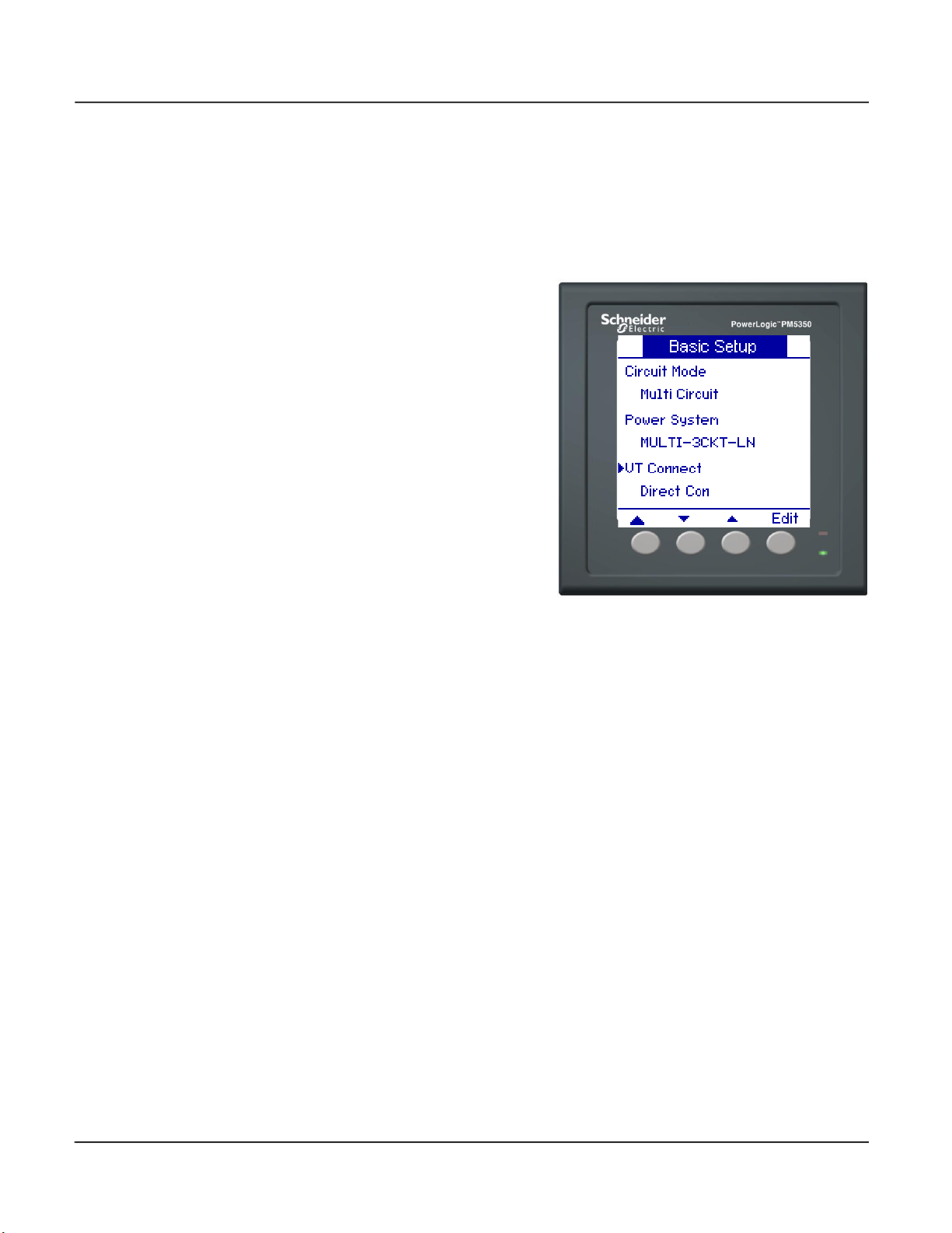
PowerLogic™ Power Meter PM5350 63230-401-203A5
Basic Setup for Multi Circuit Mode 03/2021
Setting Up Voltage Connection and CT Options
The options available for voltage connections (VT Connect) and the number of CTs that
can be selected (CT on Terminal) depend on the power system selected in “Setting Up
the Power System” on page 80.
To set up voltage connections and CTs in Multi Circuit mode:
1. Press
2. Press + and - to scroll through the
3. Press [OK] to select the VT
4. Press
5. Press + and - to scroll through the
6. Press [OK] to select VT Primary
7. Press
8. Press + and - to scroll through the
9. Press [OK] to select VT Secondary
10. Press
11. Press + and - to scroll through the
12. Press [OK] to enter the terminals
13. Press
14. Press + to increment the active
15. Press
16. Continue until all values are
▼ to select VT Connect,
then press [Edit].
VT Connect options.
Connect. If you choose Direct Con,
skip to step 10.
▼ to select VT Primary (V),
then press [Edit].
options.
(V).
▼ to select VT Secondary
(V), then press [Edit].
options.
(V).
▼ to select CT on
Terminal, then press [Edit].
terminal options.
NOTE: Options are based on the
selected power system.
the CTs are on.
▼ to select CT Primary (A),
then press [Edit].
digit through the numerals 0-9.
to enter the selected
value for the active digit and move
to the next digit to the left.
selected, then press [OK] to enter
the CT Primary.
© 2021 Schneider Electric. All Rights Reserved.82

63230-401-203A5 PowerLogic™ Power Meter PM5350
03/2021 Basic Setup for Multi Circuit Mode
Setting Up Voltage Connection and CT Options (continued)
17. Press ▼ to select CT Secondary
(A), then press [Edit].
18. Press + and - to scroll through a
list of CT Secondary options.
NOTE: CT Secondary options are
5A or 1A. See “Specifications” on
page 65 for accuracy level.
19. Press [OK] to select the CT
Secondary.
20. Press
▲ to return to the previous
screen.
NOTE: If existing associations will
be lost by making the new
selection, a confirmation screen
appears.
— Press [Yes] to accept the
changes and return to the
previous screen.
— Press [No] to keep the existing
configuration and return to the
previous screen.
© 2021 Schneider Electric. All Rights Reserved.
83
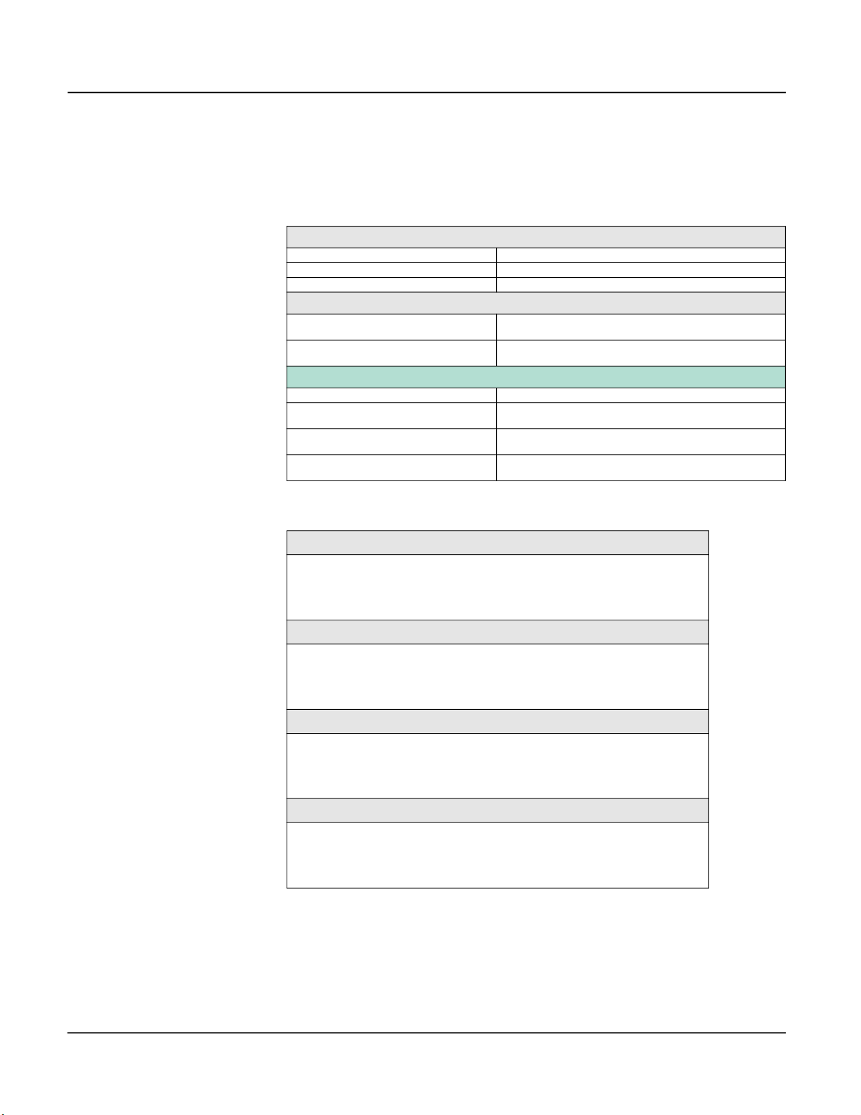
PowerLogic™ Power Meter PM5350 63230-401-203A5
Metering 03/2021
Metering
The power meter characteristics below are specific to multi circuit mode. See “Power
Meter Characteristics” on page 29 for a list of all power meter characteristics.
Table E–2: Power Meter Characteristics in Multi Circuit Mode
Energy Values Per Circuit
Active energy (Delivered) 0 to 9.2 x 10¹⁸ Wh
Reactive energy (Delivered + Received) 0 to 9.2 x 10
Apparent energy (Delivered) 0 to 9.2 x 10
Demand Values
Current
Active, reactive, apparent power
Average
Per circuit
Total
Per circuit
Maximum Demand Values
Maximum current Per circuit
Maximum active power
Maximum reactive power
Maximum apparent power
Total
Per circuit
Total
Per circuit
Total
Per circuit
18
VARh
18
VAh
Table E–3: Demand Readings
Demand Current, Average or Per Circuit
Last Complete Interval
Present Incomplete Interval
Predicted
Peak
Demand Real Power, 3Ø Total or Per Circuit
Last Complete Interval
Present Incomplete Interval
Predicted
Peak
Demand Reactive Power, 3Ø Total or Per Circuit
Last Complete Interval
Present Incomplete Interval
Predicted
Peak
Demand Apparent Power, 3Ø Total or Per Circuit
Last Complete Interval
Present Incomplete Interval
Predicted
Peak
© 2021 Schneider Electric. All Rights Reserved.84

63230-401-203A5 PowerLogic™ Power Meter PM5350
03/2021 Multi Circuit Alarms
Multi Circuit Alarms
The power meter has nine multi circuit alarms. These alarms are only available when
Multi Circuit mode is selected. Alarms and alarm parameters are listed below.
Table E–4: List of Multi Circuit Alarms
Alarm Label Alarm Parameters Value/Options
Breaker Rating Amps
High High PU%
High High DO%
High PU%
High DO%
Low PU%
MultiLevel I Ckt 1
MultiLevel I Ckt 2
MultiLevel I Ckt 3
KW Demand Ckt 1
KW Demand Ckt 2
KW Demand Ckt 3
KW Ckt 1
KW Ckt 2
KW Ckt 3
1
For multi-level alarms, pickup and dropout values cannot overlap:
0 < Low Low PU < Low Low DO < Low PU < Low DO < High DO < High PU < High High DO < High High PU < 200%
2
Multi Circuit mode does not support high priority alarms.
Low DO%
Low Low PU%
Low Low DO%
Pickup Time Delay Seconds
Enable Disable (default) or enable
Priority None (default), medium, low
Select Dig Input
Select Dig Output
Pickup Setpoint Kilowatts
Pickup Time Delay Seconds
Dropout Setpoint Kilowatts
Dropout Time Delay Seconds
Enable Disable (default) or enable
Priority None (default), medium, low
Select Dig Output
Pickup Setpoint Kilowatts
Pickup Time Delay Seconds
Dropout Setpoint Kilowatts
Dropout Time Delay Seconds
Enable Disable (default) or enable
Priority None (default), medium, low
Select Dig Output
Percent of circuit breaker rating
None, Dig Input DI1, Dig Input DI2, Dig Input DI3, Dig
Input DI4
None, Dig Output D01, Dig Output D02, Dig Output
D01 & D02
None, Dig Output D01, Dig Output D02, Dig Output
D01 & D02
None, Dig Output D01, Dig Output D02, Dig Output
D01 & D02
1
2
2
2
© 2021 Schneider Electric. All Rights Reserved.
85

PowerLogic™ Power Meter PM5350 63230-401-203A5
Multi Circuit Alarms 03/2021
Setting Up Multi Circuit Alarms
HAZARD OF UNDELIVERED NOTIFICATIONS
Do not rely solely on the power meter for alarm notifications where human or equipment
safety relies on successfully delivered notifications.
Failure to follow these instructions can result in death, serious injury, or
equipment damage.
Follow the steps in “Alarm Setup” on page 42 to reach the alarm setup screen.
To set up multi circuit alarms:
1. Press [Multi]. The multi circuit
alarm Select screen appears.
2. Press
3. Press [Edit] to select an alarm to
4. Press [Edit] to select Breaker
5. Press + to increment the active
6. Press
7. Continue until all values are
8. For pickup and dropout items
9. Follow steps 5 to 7 to set pickup
10. Press
▼ and ▲ to scroll
through the list of multi circuit
alarms.
be configured. For MultiLevel I
alarms, follow steps 4 to 21. For
KW Demand and KW alarms, skip
to step 21.
Rating.
digit through the numerals 0-9.
to enter the selected
value for the active digit and move
to the next digit to the left.
selected, then press [OK] to enter
the breaker rating.
(High High PU%, High High
DO%, High PU%, High DO%,
Low PU%, Low DO%, Low Low
PU%. Low Low DO%), press
to select the item, then press
[Edit].
and drop out values.
NOTE: Values up to 200% of the
breaker rating are allowed.
▼
▼and follow Steps 5 to 7
for Pickup Time Delay (s).
© 2021 Schneider Electric. All Rights Reserved.86

63230-401-203A5 PowerLogic™ Power Meter PM5350
03/2021 Multi Circuit Alarms
Setting Up Multi Circuit Alarms (continued)
11. Press ▼ to select Enable, then
press [Edit].
12. Press + and - to scroll between
Yes and No.
13. Press [OK] to enable or disable
the alarm.
14. Press
15. Press + and - to scroll through
16. Press
17. Press + and - to scroll through the
18. Press [OK] to select a digital input
19. Press
20. Press
▼ to select Priority, then
press [Edit].
priority options None, Medium, or
Low.
NOTE: Multi circuit alarms do not
use the High priority level. See
“Alarm Priorities” on page 41 for
more information.
▼ to select Select Dig
Input, then press [Edit].
list of digital inputs to associate
with the alarm.
to be associated with the selected
alarm.
▼ to select Select Dig
Output, then press [Edit]. Follow
steps 16 to 18 for Select Dig
Output.
▲ to save all alarm
selections and return to the
previous screen.
© 2021 Schneider Electric. All Rights Reserved.
87

PowerLogic™ Power Meter PM5350 63230-401-203A5
Multi Circuit Alarms 03/2021
Setting Up Multi Circuit Alarms (continued)
21. For KW Demand and KW
alarms, press [Edit] to select
Pickup Setpoint.
22. Press + to increment the active
digit through the numerals 0-9.
23. Press
24. Continue until all values are
25. Press
26. Press
27. Press
to enter the selected
value for the active digit and
move to the next digit to the
left.
selected, then press [OK] to
enter the pickup setpoint.
▼and follow Steps 22
to 24 for Pickup Time Delay (s).
Dropout Setpoint, and Dropout
Time Delay,
▼and follow Steps 11
to 19 for Enable, Priority, Select
Dig Output.
▲ to save all alarm
selections and return to the
previous screen.
© 2021 Schneider Electric. All Rights Reserved.88

63230-401-203A5 PowerLogic™ Power Meter PM5350
03/2021 Multi Circuit Alarms
Viewing Multi Circuit Alarm Activity and History
The power meter displays any active alarm whether it is in Normal or Multi Circuit mode.
See “Viewing Alarm Activity and History” on page 48 for information on viewing active
alarms, alarm history, and alarm counters. Multi circuit alarms do not appear in the
unacknowledged alarms list.
Multi Circuit Event Types
The Event parameter is Pickup or Dropout except for multi-level alarms.
Table E–5: Events by Alarm Type
Alarm Type Event
HH Pickup
HH Dropout
H Pickup
H Dropout
Multi Level I Ckt 1
Multi Level I Ckt 2
Multi Level I Ckt 3
KW Demand Ckt 1
KW Demand Ckt 2
KW Demand Ckt 3
KW Ckt 1
KW Ckt 2
KW Ckt 3
L Pickup
L Dropout
LL Pickup
LL Dropout
Tripped
NOTE: Other multi-level alarm types are suppressed
when the event type is Tripped.
Pickup
Dropout
Pickup
Dropout
© 2021 Schneider Electric. All Rights Reserved.
89

PowerLogic™ Power Meter PM5350 63230-401-203A5
Multi Circuit Alarms 03/2021
Multi Circuit Alarm on Phase
The Phase parameter shows the phase on which the alarm event occurred.
Table E–6: Multi Circuit Alarm on Phase by Power System Type
Alarm Type
MultiLevel I Ckt 1 A A B A
MultiLevel I Ckt 2 B B C C
MultiLevel I Ckt 3 C
KW Demand Ckt 1 A A B A
KW Demand Ckt 2 B B C C
KW Demand Ckt 3 C
KW Ckt 1 A A B A
KW Ckt 2 B B C C
KW Ckt 3 C
Multi Circuit Alarm Values
The Value field shows the alarm trigger point. For multi-level alarms, the value is in amps.
For KW and KW Demand alarms, it is the pickup or dropout value.
Command Interface with Multi-Level Alarms
See “Command Interface” on page 73 for information on using the command interface.
The command number and parameters for Multi-Level Alarm Setup are available in the
register list. For information on accessing the register list, see “Register List” on page 64.
MULTI-
3CKT-LN
MULTI2CKT-LL
(AB_BC)
MULTI2CKT-LL
(BC_CA)
MULTI2CKT-LL
(AB_CA)
MULTI-CKT-
WYE
A, B, C
(Any or all)
A, B, C
(Any or all)
A, B, C
(Any or all)
Quick Read Block for Modbus Reads
The Quick Read block is a block of registers mirrored from the standard register map that
allows basic meter values to be gathered with a single Modbus block read. This
information can be found in the Application Specific Registers > Meter Data (Quick Read)
category of the register list. For information on accessing the register list, see “Register
List” on page 64.
© 2021 Schneider Electric. All Rights Reserved.90

63230-401-203A5 PowerLogic™ Power Meter PM5350
~
LOAD
LOAD
Whetting voltage
Digital inputs
Relay outputs
(load control)
Overcurrent
protective device
(not supplied)
2
RS-485
Communications
13 14 15 16
201918 232221 242526
D0-
D1+
DI1 DI2 DI3 DI4
+
-/C
DO1
DO2
3-pole circuit breaker with
auxillary contact
CKT
LOAD
L1 L2 L3
1
03/2021 Input/Output Capabilities
Input/Output Capabilities
Monitoring for Tripped Status with a Digital Input
UNINTENDED EQUIPMENT OPERATION
• Do not use this device for critical control or protection applications where human or
equipment safety relies on the operation of the control action.
• Do not rely solely on device data to determine if your power system is functioning
correctly or meeting all applicable standards and compliances.
• Do not use device control for time-critical functions because delays can occur
between the time a control action is initiated and when that action is applied.
• Do not use digital inputs for voltage sensing applications over 36 Vdc.
Failure to follow these instructions can result in death, serious injury, or
equipment damage.
You can monitor the tripped status of a circuit breaker with a multi-level alarm by wiring
the circuit breaker auxiliary contact to a digital input on the power meter (Figure E–5). KW
and KW Demand alarms cannot be associated with the tripped condition.
Digital inputs are event-driven. The power meter only registers a circuit breaker trip when
there is an Off-to-On transition. A Tripped alarm event is triggered through a contact
closure and not through detection of zero current.
Figure E–5: Wiring a Circuit Breaker Auxiliary Contact to the Power Meter
1
2
Circuit breaker will be 1-, 2-, or 3-pole depending on your power system configuration.
The overcurrent protective device must be rated for the short-circuit current at the connection point.
© 2021 Schneider Electric. All Rights Reserved.
91

PowerLogic™ Power Meter PM5350 63230-401-203A5
Input/Output Capabilities 03/2021
To set up a multi-level alarm to monitor for circuit breaker tripped status:
1. Follow the steps for setting up a
multi-level alarm in “Setting Up
Multi Circuit Alarms” on page 86.
2. For Select Dig Input, select the
input that is wired to the circuit
breaker auxiliary contact.
NOTE: If the selected digital input
is set to operate in Demand Sync
mode, the input’s association with
a multi-level alarm will override
this setting. The digital input will
return to Demand Sync mode
when association with the multilevel alarm is removed. See
“Setting Up the Digital Inputs” on
page 52 for more information on
input control modes.
3. Press
▲ to save all alarm
selections and return to the
previous screen.
Digital Outputs in Multi Circuit Mode
Digital outputs can be associated with all types of multi circuit alarms. See “Digital
Outputs” on page 55 for information on configuring digital outputs.
LEDs
See “Setting Up the Energy/Alarm LED” on page 60 to reach the LED setup screen.
Available multi circuit LED modes are described below.
• Energy—Flashes at a rate proportional to the total amount of energy consumed. Per
circuit values are not selectable options for LED output.
• Alarm—If the LED is configured to flash on alarms, it will not flash on multi circuit
alarms because these alarms will not have a priority of High. The LED will flash for any
configured non-multi-circuit alarms.
• Off—Turns off the LED.
© 2021 Schneider Electric. All Rights Reserved.92
 Loading...