


63230-314-200/A2
8/2001
Instruction Bulletin
POWERLOGIC®Ethernet Gateway
EGX200
Retain for future use.
NOTICE
Read these instructions carefully and look at the equipment to become familiar with the
device before trying to install, operate, or maintain it. The following special messages
may appear throughout this bulletin or on the equipment to warn you of potential
hazards or to call attention to information that clarifies or simplifies a procedure.
The addition of either symbol to a “Danger” or “Warning” safety label indicates that an
electrical hazard exists which will result in personal injury if the instructions are not
followed.
This is the safety alert symbol. It is used to alert you to potential personal injury
hazards. Obey all safety messages that follow this symbol to avoid possible injury or
death. CAUTION, used without the safety alert symbol, indicates a potentially
hazardous situation which, if not avoided, can result in property damage.
DANGER
DANGER indicates an imminently hazardous situation which, if not avoided, will
result in death or serious injury.
WARNING
PLEASE NOTE
WARNING indicates a potentially hazardous situation which, if not avoided, can
result in death or serious injury.
CAUTION
CAUTION indicates a potentially hazardous situation which, if not avoided, can
result in minor or moderate injury.
CAUTION
CAUTION, used without the safety alert symbol, indicates a potentially hazardous
situation which, if not avoided, can result in property damage.
NOTE: Provides additional information to clarify or simplify a procedure.
This electrical equipment should be serviced only by qualified personnel. No
responsibility is assumed by Schneider Electric for any consequences arising out of
the use of this material. This document is not intended as an instruction manual for
untrained persons.
CLASS A FCC STATEMENT
This equipment has been tested and found to comply with the limits fora Class A digital
device, pursuant to part 15 of the FCC Rules. These limits are designated to provide
reasonable protection against harmful interference when the equipment is operated in
a commercial environment. This equipment generates, uses, and can radiate radio
frequency energy and, if not installed and used in accordance with the instruction
manual, may cause harmful interference to radio communications. Operation of this
equipment in a residential area is likely to cause harmful interference in which case the
user will be required to correct the interference at his own expense.
© 2001 Schneider Electric All Rights Reserved

63230-314-200/A2
8/2001 Contents
CONTENTS
CHAPTER 1—INTRODUCTION.........................................1
CHAPTERCONTENTS ............................................... 1
ABOUTTHISDOCUMENT............................................. 1
PRODUCT DESCRIPTION............................................. 1
EGX200BOXCONTENTS............................................. 3
EGX200COMPONENTS .............................................. 4
CHAPTER 2—SAFETY PRECAUTIONS.................................. 5
CHAPTER 3—GETTING STARTED . .................................... 7
CHAPTERCONTENTS ............................................... 7
INTRODUCTION..................................................... 7
EGX200QUICKSTARTCHECKLIST .................................... 7
EGX200INITIALSETUP............................................... 8
SetupUsingaWebBrowser......................................... 8
SetupUsingHyperTerminal......................................... 13
AccessingtheEGX200SetupUtility ............................... 13
CHAPTER 4—INSTALLATION AND WIRING.............................17
CHAPTERCONTENTS .............................................. 17
MOUNTINGLOCATIONSANDINSTALLATION...........................17
Dimensions ..................................................... 18
MountingOptions.................................................19
Wall/Panel Mounting . . . ........................................ 19
DIN Rail Mounting ............................................. 20
FlatSurfaceMounting .......................................... 20
WIRINGCONNECTIONS.............................................21
ControlPowerWiring..............................................21
ControlPowerLED............................................. 21
RS-485SerialPorts............................................... 22
4-WireCommunication.......................................... 23
2-WireCommunication.......................................... 23
DaisyChainMaximumDistances..................................24
RS-232SerialPort................................................25
COM1andCOM2LEDs .......................................... 25
© 2001 Schneider Electric All Rights Reserved
i

63230-314-200/A2
Contents 8/2001
BiasingandTermination.......................................... 26
RS-485Configuration......................................... 26
4-WireConfiguration ......................................... 26
2-WireConfiguration ......................................... 26
EthernetPorts.................................................. 27
EthernetLEDs ................................................. 27
CHAPTER 5—OPERATION ......................................... 29
CHAPTERCONTENTS............................................. 29
ACCESSING THE EGX200 OVER A NETWORK ......................... 29
LoggingintotheEGX200......................................... 29
EGX200EMBEDDEDWEBPAGEOPTIONS............................ 31
CommunicationsSettings......................................... 31
EthernetPortSetupviaLAN ................................... 32
SerialCOMPortSetup........................................ 32
DeviceList .................................................... 32
Diagnostics. . . ................................................. 35
PasswordAdministration ......................................... 36
AdministratorAccount ........................................ 36
User Account ............................................... 36
AdvancedSetup................................................ 38
LoggingOut ................................................... 38
APPENDIXA—MAINTENANCEANDTROUBLESHOOTING............... 39
MAINTENANCE................................................... 39
TROUBLESHOOTING.............................................. 39
APPENDIXB—FIRMWAREUPDATES ................................ 41
APPENDIXC—COMMUNICATINGWITHSMSUSINGTHEEGX200 ........ 43
APPENDIX D—SPECIFICATIONS .................................... 45
INDEX .......................................................... 47
ii
© 2001 Schneider Electric All Rights Reserved

63230-314-200/A2 Chapter 1—Introduction
8/2001 Chapter Contents
CHAPTER 1—INTRODUCTION
CHAPTER CONTENTS
CHAPTERCONTENTS .................................................. 1
ABOUTTHISDOCUMENT................................................ 1
PRODUCT DESCRIPTION. ............................................... 1
EGX200BOXCONTENTS................................................ 3
EGX200COMPONENTS ................................................. 4
ABOUT THIS DOCUMENT
This document contains installation and operation instructions for the POWERLOGIC
Ethernet Gateway (EGX200). To install the EGX200, you should have a general
understanding of the POWERLOGIC Power Monitoring and Control System related
products and technology.
For more information about the POWERLOGIC system, see the following documents:
• POWERLOGIC System Manager (SMS) Software User's Guide
• POWERLOGIC System Architecture and Application Guide
PRODUCT DESCRIPTION
The POWERLOGIC EGX200 is an Ethernet-based device that provides a transparent
interface between Ethernet-based networks and field devices. Field devices include
meters, monitors, protective relays, PLCs, trip units, and other devices that
communicate using MODBUS, JBUS or POWERLOGIC protocol.
The EGX200 uses MODBUS/TCP protocol to access power monitoring information
across a local area network (LAN) or a wide area network (WAN). This capability allows
the use of power monitoring software to access information from devices for data
collection, trending, alarm/event management, harmonic analysis, and other functions.
®
© 2001 Schneider Electric All Rights Reserved
1

Chapter 1—Introduction 63230-314-200/A2
Product Description 8/2001
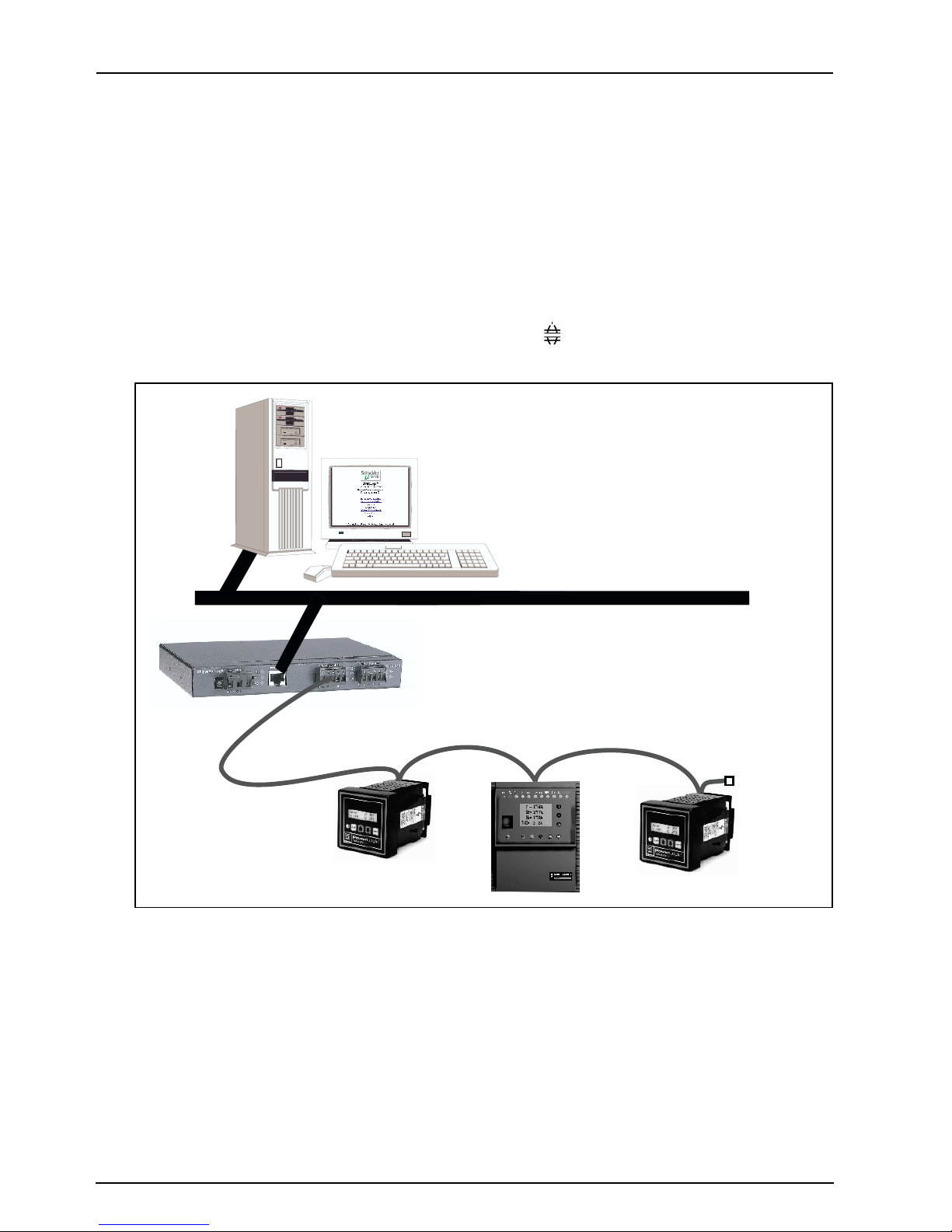
In addition, the EGX200 contains a web server, which lets you remotely configure and
troubleshoot both Ethernet and serial communication parameters. A typical application
example is shown in Figure 1–1.
MODBUS
TCP/IP
Sepam 1000
Series 20
System Manager
®
EGX200
POWERLOGIC
ETHERNET
Modicon
Quantum PLC
with NOE Card
+
Standard Web
Browser
EGX200
®
Series 4000
Circuit Monitor
PowerLink G3
panelboard
Figure 1–1: System architecture example showing EGX200 installed for
Ethernet connectivity
2
Power Meter
Circuit Monitor
Enercept Meters
© 2001 Schneider Electric All Rights Reserved

63230-314-200/A2 Chapter 1—Introduction
8/2001 EGX200 Box Contents
EGX200 BOX CONTENTS
The following items are provided for installation and operation of the EGX200:
• EGX200 unit with all connectors plugged in
• 24 Vdc switching power supply (wall mountable with global plug kit)
• EGX200 mounting kit, containing rubber feet and DIN rail adapters
• Mounting template
• Instruction Bulletin for the installation and operation of the EGX200 and the
power supply
• Registration card
© 2001 Schneider Electric All Rights Reserved
3
Chapter 1—Introduction 63230-314-200/A2
EGX200 Components 8/2001
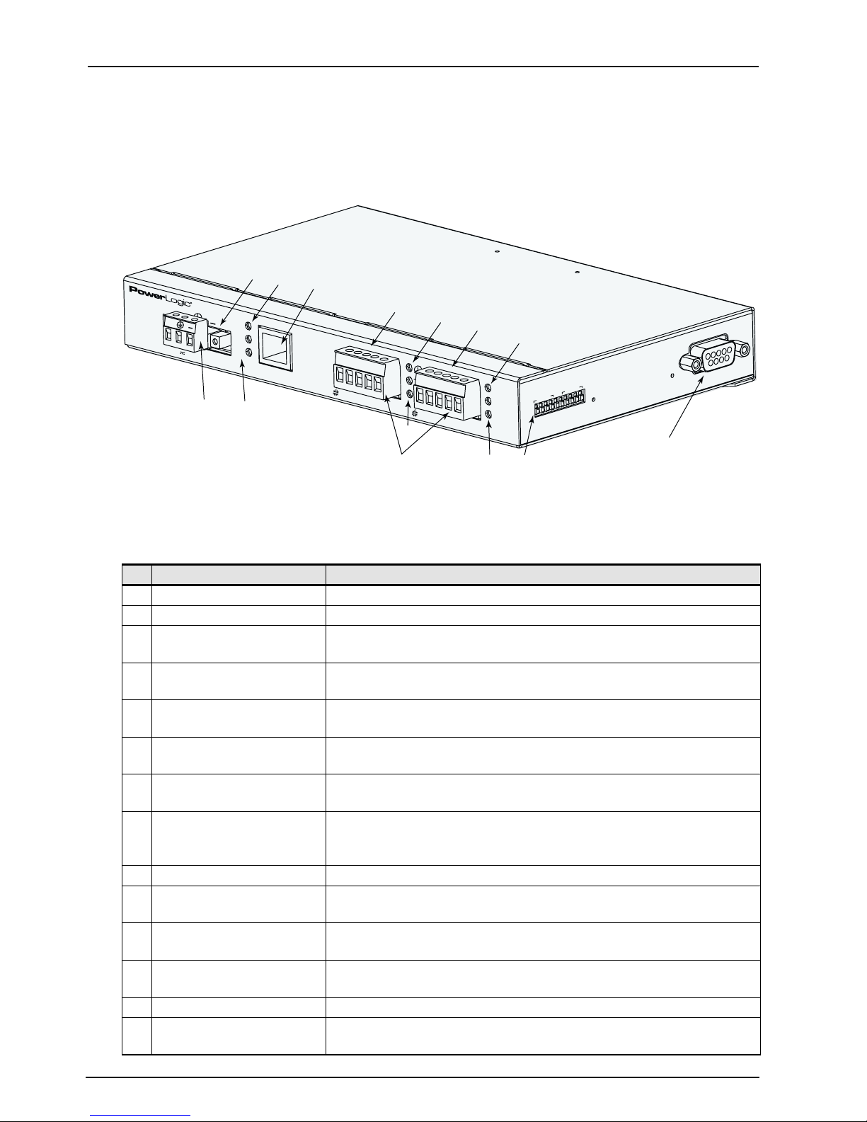
EGX200 COMPONENTS
Figure 1–2 shows the components of the EGX200. Table 1–1 identifies those
components and explains their functions.
1
3
5
system
+
+
24V
8W
2
Lx
Tx
Rx
4
10/100 Base T
10
9
R
x-
Figure 1–2: Identifying EGX200 components
6
C
O
M
1 (
R
S
-
4
85)
8
7
6
R
x+
Tx-
Tx+
7
10
11
C
O
M
2 (
R
S
-
4
5
Rx-
8
85)
4
3
2
Rx
+
Tx-
T
RS
1
x
+
-
48
5
Tx
Rx
COM 1
RS-485 Configuration
2
M
O
C
8
7
6
5
4
3
2
1
10
9
COM 2 (RS-232)
13
9
12
14
Table 1–1: EGX200 Components
No. Item Description
1 Control Power Connection 24 Vdc connection for control power to the EGX200.
2 Control Power Connector 3-position male terminal block for 24 Vdc control power connection.
3EthernetLinkLED
4 Ethernet Port LEDs
10/100 Base T port
5
(twisted pair)
6 COM 1 (RS-485)
7 Power LED
8COM1LEDs
9 RS-485 Connectors 5-position female terminal block for RS-485 ports 1 and 2.
10 COM 2 (RS-485)
11 RS-485 LED
12 COM 2 LEDs
13 COM 2 (RS-232) DB-9 port is used for initial network setup or for serial communication.
14 Dip Switches
LED illuminates yellow steadily when there is a proper Ethernet
physical connection.
A yellow LED illuminates when the EGX200 is receiving data (Rx).
A green LED illuminates when the EGX200 is transmitting data (Tx).
This port drives a twisted pair Cat. 5 cable up to approximately 328 ft
(100 m). This port has a standard RJ-45 connector.
RS-485 port 1 is used for connecting POWERLOGIC, JBUS, or
MODBUS daisy-chained devices.
This green LED illuminates steadily when minimum control power is
applied to the unit.
The yellow LED illuminates when COM 1 is receiving data (Rx); the
green LED illuminates when COM 1 is transmitting data (Tx). Both
LEDs flicker intermittently if there is a configuration error.
RS-485 port 2 is used for connecting POWERLOGIC, JBUS, or
MODBUS daisy-chained devices.
If using COM 2 as RS-485, the RS-485 LED illuminates green; if using
COM 2 as RS-232, the RS-485 LED is not lit.
The yellow LED illuminates when COM 2 is receiving data (Rx); the
green LED illuminates when COM 2 is transmitting data (Tx).
Provide custom configuration options for COM 1 and COM 2 biasing
and termination.
4
© 2001 Schneider Electric All Rights Reserved

63230-314-200/A2 Chapter 2—Safety Precautions
8/2001
CHAPTER 2—SAFETY PRECAUTIONS
This chapter contains important safety precautions that must be followed before
attempting to install, service, or maintain electrical equipment. Carefully read and
follow the safety precautions outlined below.
DANGER
HAZARD OF ELECTRIC SHOCK, BURN, OR EXPLOSION
• Only qualified workers should install this equipment. Such work
should be performed only after reading this entire set
of instructions.
• NEVER work alone.
• Before performing visual inspections, tests, or maintenance on this
equipment, disconnect all sources of electric power. Assume that all
circuits are live until they have been completely de-energized, tested,
and tagged. Pay particular attention to the design of the power
system. Consider all sources of power, including the possibility of
backfeeding.
• Turn off all power supplying the equipment in which the EGX200 is to
be installed before installing and wiring the EGX200.
• Beware of potential hazards, wear personal protective equipment,
and carefully inspect the work area for tools and objects that may
have been left inside the equipment.
• The successful operation of this equipment depends upon proper
handling, installation, and operation. Neglecting fundamental
installation requirements may lead to personal injury as well as
damage to electrical equipment or other property.
Failure to observe these instructions will result in death or
serious injury.
© 2001 Schneider Electric All Rights Reserved
5

Chapter 2—Safety Precautions 63230-314-200/A2
8/2001
6
© 2001 Schneider Electric All Rights Reserved

63230-314-200/A2 Chapter 3—Getting Started
8/2001 Chapter Contents
CHAPTER 3—GETTING STARTED
CHAPTER CONTENTS
CHAPTERCONTENTS .................................................. 7
INTRODUCTION . . ..................................................... 7
EGX200QUICKSTARTCHECKLIST ....................................... 7
EGX200INITIALSETUP .................................................8
SetupUsingaWebBrowser........................................... 8
SetupUsingHyperTerminal...........................................13
AccessingtheEGX200SetupUtility................................. 13
INTRODUCTION
This chapter contains a quick reference that lists the steps necessary to install and
operate the EGX200, as well as the initial instructions for setting up the EGX200 before
installation.
EGX200 QUICK START CHECKLIST
Use the steps in Table 3–1 as a quick start checklist for the EGX200. For complete
instructions, refer to the chapter listed:
Tab le 3–1: Quick Start Checklist
Steps Reference
1. Wire the control power. Chapter 4—Installation and Wiring
2. Set up the EGX200 for Ethernet communication via
HyperTerminal or web browser.
3. Install the EGX200. Chapter 4—Installation and Wiring
Chapter 3—Getting Started
4. Wire your RS-485 devices to the serial ports. Chapter 4—Installation and Wiring
5. Launch your browser to configure the serial
communication parameters.
© 2001 Schneider Electric All Rights Reserved
Chapter 5—Operation
7

Chapter 3—Getting Started 63230-314-200/A2
EGX200 Initial Setup 8/2001
EGX200 INITIAL SETUP
Before configuring the EGX200, obtain a unique static IP address, subnet mask, and
router IP address from your network administrator.
Table 3–2: Options for Ethernet Communications Setup
Option Selection Description Default
IP Address The EGX200 Ethernet IP network address (static IP required) 10.10.10.10
Subnet Mask The Ethernet IP subnet mask address of your network 255.255.255.0
Router IP Address The router used for wide area network (WAN) communications 0.0.0.0
There are two ways to initially set up and assign the EGX200 Ethernet parameters:
• UsingaWebBrowser
• Using HyperTerminal
Setup Using a Web Browser
The EGX200 has a web server that includes embedded pages that let you configure
Ethernet and serial communication parameters, add serial devices, enter passwords,
and access diagnostics. The EGX200 ships with a default IP address (10.10.10.10)
and a subnet mask default address (255.255.255.0) that can be used to access these
web pages. The Communication Settings web page is used to set up the desired IP
address, subnet mask, and router IP address to match the network configuration.
To access the EGX200 Communication Settings web page using a browser, follow
these steps:
1. Connect a cross-over Ethernet cable from the EGX200 to the PC, as shown in
Figure 3–1.
+
Connect to 24Vdc
power source
To Earth ground
-
Figure 3–1: Connecting PC to EGX200 using cross-over Ethernet cable
8
Cross-over
Ethernet cable
© 2001 Schneider Electric All Rights Reserved

63230-314-200/A2 Chapter 3—Getting Started
8/2001 EGX200 Initial Setup
2. Power the EGX200 by connecting a 24 Vdc power source to its control power
connection.
Make sure that the control power is properly Earth grounded (see Control Power
Wiring on page 19).
3. For the PC, force the static IP address (10.10.10.11) and a subnet mask
(255.255.255.0).
An example using Microsoft Windows
®
NT is shown in the following substeps. For
help with other systems, contact your network administrator.
a. From your PC’s task bar, Click Start > Settings > Control Panel.
The Control Panel screen displays.
b. From the Control Panel screen, select Network.
The Network dialog box displays.
c. From the Network dialog box, select the Protocols tab.
The Network Protocols dialog box displays, as shown in Figure 3–2.
Figure 3–2: Entering the Network Protocol
d. For Network Protocols, select TCP/IP Protocol, and then click Properties.
© 2001 Schneider Electric All Rights Reserved
9

Chapter 3—Getting Started 63230-314-200/A2
EGX200 Initial Setup 8/2001
The Microsoft TCP/IP Properties dialog box displays, as shown in Figure 3–3.
Figure 3–3: Entering the IP Address and Subnet Mask
e. From the Microsoft TCP/IP Properties dialog box, select “Specify a IP address.”
f. Enter the IP address (10.10.10.11) and subnet mask (255.255.255.0), and then
click OK.
g. Reboot your PC, if required.
4. Launch a standard web browser such as Internet Explorer.
5. In the browser address field (see Figure 3–4), type the EGX200 IP address
(10.10.10.10), and press Enter.
Figure 3–4: IP address entered in browser address field
10
© 2001 Schneider Electric All Rights Reserved
63230-314-200/A2 Chapter 3—Getting Started
8/2001 EGX200 Initial Setup
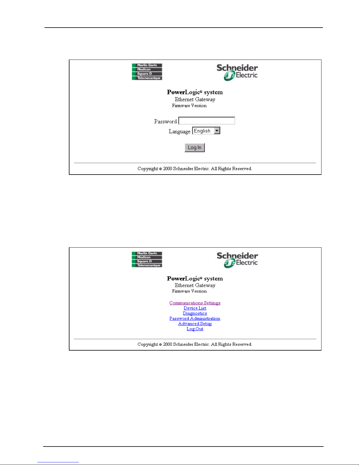
The EGX200 login page displays, as shown in Figure 3–5.
X.XXX
Figure 3–5: EGX200 Login page
6. From the Language pull-down menu, select the desired language.
7. In the Password field, type: admin
8. Click Log In.
The EGX200 Home page displays, as shown in Figure 3–6.
X.XXX
Figure 3–6: EGX200 Home page
9. Click Communication Settings to set up Ethernet and serial communication
parameters.
© 2001 Schneider Electric All Rights Reserved
11

Chapter 3—Getting Started 63230-314-200/A2
EGX200 Initial Setup 8/2001
The Communications Settings page displays, as shown in Figure 3–7.
Figure 3–7: Communications Settings page
10. Enter your IP Address, Subnet Mask, and Router IP address, and click Update.
11. Reset your PC back to its original network configuration.
Now you are ready to install and use the EGX200 on your Ethernet network. Refer to
Chapter 4 and Chapter 5 for more information.
12
© 2001 Schneider Electric All Rights Reserved

63230-314-200/A2 Chapter 3—Getting Started
8/2001 EGX200 Initial Setup
Setup Using HyperTerminal
The EGX200 has a setup utility that can be accessed using the HyperTerminal
program for the Microsoft Windows operating system, or an equivalent terminal
emulator.
Accessing the EGX200 Setup Utility
To access the EGX200 setup utility, follow these steps:
1. Attach a null modem cable between the RS-232 COM port (COM 2) of the EGX200
and a Microsoft Windows-based PC, as shown in Figure 3–8.
Null
Modem
cable
+
Connect to 24Vdc
power source
-
To Earth ground
Catalog #:
EGWNMC
Figure 3–8: Connecting PC to EGX200 using Null Modem cable
2. From your PC, launch HyperTerminal. To do this, from the Windows Explorer task
bar, click Start > Programs > Accessories > Hyperterminal > HyperTerminal.
© 2001 Schneider Electric All Rights Reserved
13

Chapter 3—Getting Started 63230-314-200/A2
EGX200 Initial Setup 8/2001
The Connection Description dialog box displays, as shown in Figure 3–9.
Figure 3–9: HyperTerminal Connection Description dialog box
3. In the Name field, enter a descriptive name for your new HyperTerminal
connection, and then click OK.
The Connect To dialog box displays, as shown in Figure 3–10.
Figure 3–10: HyperTerminal Connect To dialog box
4. In the Connect using field, select the desired PC COM port, and then click OK.
14
© 2001 Schneider Electric All Rights Reserved
63230-314-200/A2 Chapter 3—Getting Started
8/2001 EGX200 Initial Setup
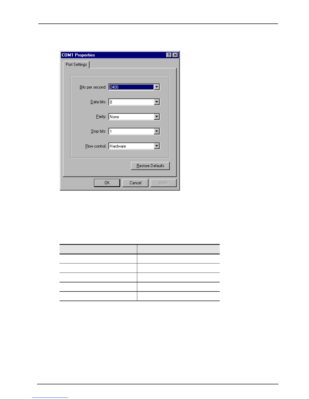
The COM port properties page displays, as shown in Figure 3–11.
Figure 3–11: HyperTerminal COM Port Properties dialog box
5. In this dialog box, set the values listed in Table 3–3.
Table 3–3: Communications Settings Parameters
Settings Value
Baud Rate 19200
Data Bits 8
Parity None
Stop Bits 1
Flow Control None
You are now ready to enter the EGX200 setup utility.
© 2001 Schneider Electric All Rights Reserved
15

Chapter 3—Getting Started 63230-314-200/A2
EGX200 Initial Setup 8/2001
6. Enter the EGX200 Setup Utility by doing the following steps:
NOTE: After applying or cycling power to the EGX200, the green COM 2 RS-485
LED turns OFF, and you have 5 seconds to press Enter on the PC keyboard to
access the EGX200 setup utility.
a. Apply power to the EGX200 by wiring the 24 Vdc connector to a power source,
or cycle the power.
b. While the COM 2 green RS-485 LED is OFF, press Enter.
The EGX200 Setup Utility menu displays, as shown in Figure 3–12. Table 3–4
provides descriptions of each menu option.
Figure 3–12: EGX200 HyperTerminal Setup Utility options
Tab le 3–4: EGX200 Setup Utility descriptions
Option No. Description Default Setting
1 Allows you to enter the unique IP address for the
EGX200
2 Allows you to enter the Subnet Mask address of the
EGX200 network
3 AllowsyoutoentertheRouterIPaddressforthe
EGX200
5 Saves the above configuration and exits the
EGX200 setup utility
10.10.10.10
255.255.255.0
0.0.0.0
You are now ready to install and use the EGX200 on your Ethernet network. Refer
to Chapter 4 and Chapter 5 for more information.
16
© 2001 Schneider Electric All Rights Reserved

63230-314-200/A2 Chapter 4—Installation and Wiring
8/2001 Chapter Contents
CHAPTER 4—INSTALLATION AND WIRING
CHAPTER CONTENTS
CHAPTERCONTENTS ................................................. 17
MOUNTINGLOCATIONSANDINSTALLATION.............................. 17
Dimensions .......................................................18
MountingOptions................................................... 19
Wall/Panel Mounting............................................. 19
DINRailMounting .............................................. 20
Flat Surface Mounting . . . ........................................20
WIRINGCONNECTIONS................................................ 21
ControlPowerWiring................................................ 21
ControlPowerLED.............................................. 21
RS-485SerialPorts................................................. 22
4-WireCommunication........................................... 23
2-WireCommunication........................................... 23
Daisy-ChainMaximumDistances................................... 24
RS-232SerialPort.................................................. 25
COM1andCOM2LEDs ............................................ 25
BiasingandTermination ............................................. 26
RS-485Configuration............................................ 26
4-WireConfiguration............................................. 26
2-WireConfiguration............................................. 26
EthernetPorts ..................................................... 27
EthernetLEDs..................................................... 27
MOUNTING LOCATIONS AND INSTALLATION
The EGX200 is designed to be set on a flat surface or mounted to a wall, a cabinet, or
other surfaces. When choosing a mounting location, consider the following points:
• Allow for easy access to the EGX200
• Allow space for all wires to be neatly routed down the side or bottom of the EGX200
Typical locations for mounting the EGX200 include the following:
• power equipment instrument compartment • auxiliary cabinet
• office or raised floor environment • factory floor environment
NOTE: Make sure you follow all equipment manufacturer’s procedures and warnings
when installing the EGX200 in electrical equipment.
© 2001 Schneider Electric All Rights Reserved
17

Chapter 4—Installation and Wiring 63230-314-200/A2
(28)
Mounting Locations and Installation 8/2001
Dimensions
Figure 4–1 shows the EGX200 dimensions, including the DIN rail mounting equipment.
1.77
4.81
(45)
(123)
1.44
(37)
0.40
(11)
7.88
(201)
1.77
(45)
3.05
(78)
7.88
(201)
8.68
(221)
Top V iew
1.07
(28)
End View
0.59
(15)
0.40
(11)
Side View
Figure 4–1: EGX200 Dimensions
18
1.07
(28)
1.07
7.88
(201)
0.59
(15)
INCHES
(MILLIMETERS)
© 2001 Schneider Electric All Rights Reserved
63230-314-200/A2 Chapter 4—Installation and Wiring
8/2001 Mounting Locations and Installation
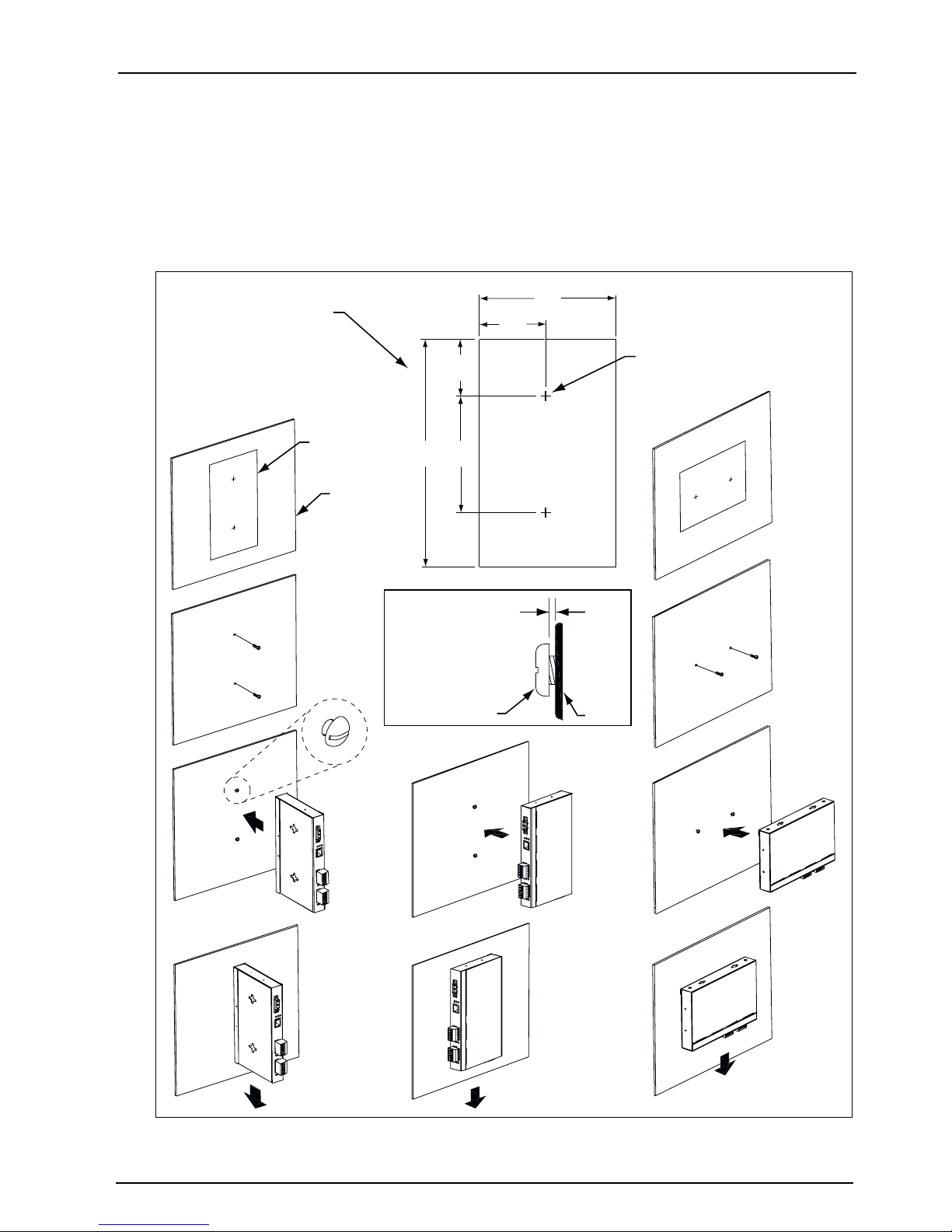
Mounting Options
Figures 4–2, 4–3, and 4–4 illustrate some of the various mounting options.
Wall/Panel Mounting
4.81
Template dimensions
2.32
(59)
(123)
INCHES
(MILLIMETERS)
Template
Panel
1.94
(50)
4.00
7.88
(102)
(201)
.036 in. (1 mm) min.
.046 in. (2 mm) max.
Pan head screw
6–32 (4 mm)
Max. drill size #6
(2 places – location A)
A
Template
A
Panel
Figure 4–2: Wall/Panel Mounting
© 2001 Schneider Electric All Rights Reserved
19

Chapter 4—Installation and Wiring 63230-314-200/A2
Mounting Locations and Installation 8/2001
DIN Rail Mounting
Feet
DIN rail
Figure 4–3: DIN Rail Mounting
Flat Surface Mounting
Figure 4–4: Feet Installation
Feet
20
© 2001 Schneider Electric All Rights Reserved

63230-314-200/A2 Chapter 4—Installation and Wiring
8/2001 Wiring Connections
WIRING CONNECTIONS
Control Power Wiring
The EGX200 accepts 24 Vdc control power with maximum power consumption of 8
watts. A 3-position male terminal block connector is provided for control power (see
Figure 4–5).
A universal 24 Vdc switching power supply rated for 20 watts is included with the
EGX200. This switching power supply must be connected to the EGX200 as shown in
Figure 4-5, in which the red wire is connected to the positive (+) terminal and the black
wire is connected to the negative (-) terminal.
If needed, another power supply or cord can be used to power the EGX200, as long
as it is rated for a minimum of 8 watts at 24 Vdc (±10% regulation).
system
+24 Vdc
+
24V
8W
+
Common
10/100 Base T
Lx
Tx
Rx
24 Vdc Control
Power Connector
C
OM 1 (
R
S-485)
10
9
8
7
6
R
x-
Rx+
Tx-
Tx+
C
OM 2 (
R
S-485)
5
4
3
2
RS-4
1
R
x
-
Rx+
Tx-
Tx+
85
RS
Tx
Rx
n
o
ti
ra
u
fig
n
o
1
C
5
COM
48
-
2
M
O
C
10
9
8
7
6
5
4
3
2
1
Black
24 Vdc Switching
Cable (6 feet)
Red
Power Supply
(included with EGX200)
To Earth ground
NOTE: The control power supply must be properly connected to a true Earth ground.
Figure 4–5: Control Power Connector
Control Power LED
A green power LED on the EGX200 remains ON to indicate it is receiving control
power. This LED is located above the COM 1 (RS-485) Rx and Tx LEDs.
COM 2 (RS-232)
© 2001 Schneider Electric All Rights Reserved
21
Chapter 4—Installation and Wiring 63230-314-200/A2
Wiring Connections 8/2001
RS-485 Serial Ports
The RS-485 serial ports are used to communicate with daisy-chained devices. The
EGX200 has two serial ports: COM 1 is always set for RS-485 communication, and
COM 2 is selectable between RS-485 and RS-232. By default, COM 2 is set for
RS-485 communication. For more information on configuring COM 2, please refer to
the Communications Settings web page on page 31.
Each port is designed to support up to a maximum of 32 devices without a repeater
(see Figure 4–6). The RS-485 ports enable communications via a 4-wire plus shield or
2-wire plus shield cable (Tx+, Tx–, Rx+, Rx-, and ).
POWERLOGIC
System Manager Software (SMS)
ETHERNET
EGX200
RS-485 Daisy Chain Connected to the EGX200 RS-485 Port
Figure 4–6: Daisy Chain Connected to EGX200 RS-485 Port
For communication wiring, we recommend the following cables:
• For 4-wire communication, use Belden 8723 or 9842 cable or equivalent.
• For 2-wire communication, use Belden 9841 cable or equivalent.
22
© 2001 Schneider Electric All Rights Reserved

63230-314-200/A2 Chapter 4—Installation and Wiring
8/2001 Wiring Connections
4-Wire Communication
For 4-wire communication using Belden 8723 cable, connect the wires to the terminal
block, as shown in Figure 4–7. If using Belden 9842 cable, see Figure 4–8.
COM 1 (RS-485)
109876
Rx+
Rx-
Black
Red
Tx-
Tx+
WhiteShield
Green
COM 2 (RS-485)
54321
Rx+
Rx-
Black
Red
Tx-
Tx+
WhiteShield
Green
Figure 4–7: Communications wiring (4-wire) with Belden 8723 cable
COM 1 (RS-485)
10 9 8 7 6
Rx-
Shield
White
with
orange
stripe
Rx+
Tx-
Orange
with
white
stripe
Tx+
White
with
blue
stripe
Blue
with
white
stripe
Shield
COM 2 (RS-485)
54321
Rx+
Rx-
White
with
orange
stripe
Tx-
Orange
with
white
stripe
Tx+
White
with
blue
stripe
Blue
white
stripe
RS-485
RS-485
with
Figure 4–8: Communications wiring (4-wire) with Belden 9842 cable
2-Wire Communication
For 2-wire communication using Belden 9841, connect the white wire to terminal Txand the blue wire to terminal Tx+, as shown in Figure 4–9. Then connect a jumper wire
from terminal Tx- to terminal Rx- and another jumper wire from terminal Tx+ to terminal
Rx+. Connect the shield wire to the shield terminal as shown.
COM 1 (RS-485)
10 9 8 7 6
Rx+
Rx-
Shield
White
with
blue
stripe
L-
Tx-
Tx+
Blue
with
white
stripe
L+
COM 2 (RS-485)
54321
Rx+
Rx-
Shield
White
with
blue
stripe
L-
Tx-
RS-485
Tx+
Blue
with
white
stripe
L+
Figure 4–9: Communications wiring (2-wire) Belden 9841 cable
© 2001 Schneider Electric All Rights Reserved
23

Chapter 4—Installation and Wiring 63230-314-200/A2
Wiring Connections 8/2001
Daisy Chain Maximum Distances
The maximum daisy chain distance is determined by the baud rate and the types of
RS-485 devices (2-wire/4-wire) on the daisy chain. The RS-485 ports will support daisy
chains that fall within the specifications shown in Tables 4–1and4–2.
Table 4–1: 4-Wire Daisy Chain Maximum Distances
Baud Rate Maxdistancefor1–16 devices Maxdistancefor17–32 devices
1200 10,000ft (3,048m) 10,000ft (3,048m)
2400 10,000ft (3,048m) 5,000ft (1,524m)
4800 10,000ft (3,048m) 5,000ft (1,524m)
9600 10,000ft (3,048m) 4,000ft (1,219m)
19200 5,000ft (1,524m) 2,500ft (762m)
38400 5,000ft (1,524m) 1,500ft (457m)
Due to the volume of RS-485 devices in the field, this table is only to be used as a guide and was tabulated
based on POWERLOGIC 4-wire devices and POWERLOGIC 4-wire devices that support 2-wire devices.
Table 4–2: 2-Wire Daisy Chain Maximum Distances
Baud Rate Maxdistancefor1–8 devices Maxdistancefor9–16 devices
1200 10,000ft (3,048m) 10,000ft (3,048m)
2400 10,000ft (3,048m) 5,000ft (1,524m)
4800 10,000ft (3,048m) 5,000ft (1,524m)
9600 10,000ft (3,048m) 4,000ft (1,219m)
19200 5,000ft (1,524m) 2,500ft (762m)
38400 2,500ft (762m) 1,500ft (457m)
Due to the volume of RS-485 devices in the field, this table is only to be used as a guide and was tabulated
based on POWERLOGIC 4-wire devices and POWERLOGIC 4-wire devices that support 2-wire devices.
24
© 2001 Schneider Electric All Rights Reserved

63230-314-200/A2 Chapter 4—Installation and Wiring
8/2001 Wiring Connections
RS-232 Serial Port
RS-232 is used to configure the EGX200 network parameters, and also can be used
for serial communication using Modbus RTU. The EGX200 RS-232 port uses a
standard DB9 male connector. The following table shows the typical serial RS-232
connector pinout.
Tab le 4–3: RS-232 Pin Assignments (DB9 EGX200 Signal Set)
Pin No. Description
Pin 1 Received Line Signal Detector (Data Carrier Detect)
Pin 2 Received Data
Pin 3 Transmit Data
Pin 4 Data Terminal Ready
Pin 5 Signal Ground
Pin 6 Data Set Ready
Pin 7 Request To Send
Pin8 ClearToSend
Pin 9 Ring Indicator
COM 1 and COM 2 LEDs
One set of LEDs is provided for each COM port. A yellow LED illuminates when the
corresponding COM port is receiving data (Rx). A green LED illuminates when data on
the corresponding COM port is transmitted (Tx). Also, above the COM 2 Rx and Tx
LEDs, a third LED (green) illuminates steadily when COM 2 is selected to be active for
RS-485 communication. The COM 2 Tx and Rx LEDs behave the same way when
used for either RS-485 or RS-232 communication.
© 2001 Schneider Electric All Rights Reserved
25
Chapter 4—Installation and Wiring 63230-314-200/A2
Wiring Connections 8/2001
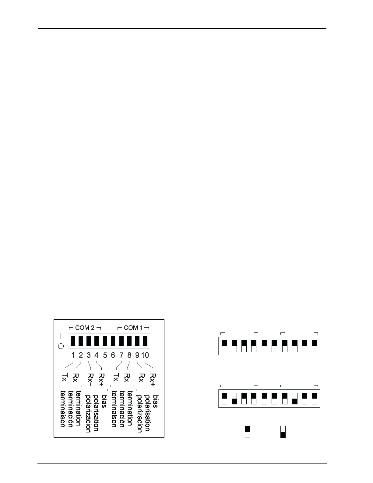
Biasing and Termination
RS-485 Configuration
On RS-485 daisy chains, correct biasing is required to ensure reliable communication
with field devices. The EGX200’s dip switches for each RS-485 port provide flexibility
in configuring the correct biasing. Figure 4–10 shows the biasing and termination label,
as well as the typical dip switch settings for both 4-wire and 2-wire configurations.
In addition, the RS-485 daisy chain should be terminated to ensure reliable
communication. The last device on the daisy chain usually needs a terminator (part
number MCT-485 or MCTAS-485). Please refer to the instruction bulletin for the last
device on the daisy chain to determine whether a terminator is required. If one is
required, contact your local sales representative.
4-Wire Configuration
For RS-485, 4-wire configuration, the biasing and termination dip switches should be
ON (switches 1, 2, 3, 4 for COM 2 and switches 7, 8, 9, and 10 for COM 1 — switches
5 and 6 are not used). The EGX200 is shipped with all dip switches in the ON position
(default). Therefore, you do not need to change the dip switches unless a different
termination or biasing is required.
2-Wire Configuration
For RS-485 2-wire communication, the biasing dip switches for Rx+ and Rx- should be
ON. The termination dip switches for either Rx or Tx should be OFF. Therefore, either
switch 7 or switch 8 should be OFF for COM 1, and either switch 1 or switch 2 should
be OFF for COM 2.
Dip switch settings
COM 2 COM 1
1234 56 78910
4-Wire
Figure 4–10: Biasing and Termination
26
COM 2 COM 1
1234 56 78910
2-Wire
= ON = OFF
© 2001 Schneider Electric All Rights Reserved

63230-314-200/A2 Chapter 4—Installation and Wiring
8/2001 Wiring Connections
Ethernet Ports
The EGX200 has one on-board 10/100BaseT Ethernet port. This port supports a
twisted pair cable up to 328 ft (100 m). Use data grade twisted-pair wire. This wire must
have a characteristic impedance of 100 ohms and meet the EIA/TIA Category 5
standard wiring specifications. The cable can be either shielded twisted pair or
unshielded twisted pair.
Ethernet LEDs
The 10/100BaseT Ethernet port has one set of LEDs. The top LED is yellow, is marked
LK (Link), and illuminates when there is a proper Ethernet physical connection. The
bottom LED is yellow and illuminates when the EGX200 is receiving data (Rx). The
middle LED is green and illuminates when data is transmitted (Tx).
© 2001 Schneider Electric All Rights Reserved
27

Chapter 4—Installation and Wiring 63230-314-200/A2
Wiring Connections 8/2001
28
© 2001 Schneider Electric All Rights Reserved

63230-314-200/A2 Chapter 5—Operation
8/2001 Chapter Contents
CHAPTER 5—OPERATION
CHAPTER CONTENTS
CHAPTERCONTENTS .................................................29
ACCESSING THE EGX200 OVER A NETWORK .............................29
LoggingintotheEGX200.............................................29
EGX200EMBEDDEDWEBPAGEOPTIONS ................................31
CommunicationsSettings ............................................31
EthernetPortSetupviaLAN ......................................32
SerialCOMPortSetup...........................................32
DeviceList........................................................32
Diagnostics . . . ....................................................35
PasswordAdministration.............................................36
Administrator Account . . . ........................................36
UserAccount ..................................................36
AdvancedSetup ...................................................38
LoggingOut.......................................................38
ACCESSING THE EGX200 OVER A NETWORK
This section tells how to access the EGX200 over a network or the Internet. After you
set up Ethernet parameters using HyperTerminal or a web browser, the EGX200 is
accessible via an Ethernet LAN and a web browser such as Internet Explorer. The
following section describes this process.
Logging into the EGX200
To log into the EGX200, follow these steps:
1. Launch your web browser (Microsoft’s Internet Explorer v. 5.0 or higher).
2. In the address field (see Figure 5–1), type the IP address of the EGX200 (for
example, 150.200.250.50), and press Enter.
Figure 5–1: IP address entered in browser address field
© 2001 Schneider Electric All Rights Reserved
29

Chapter 5—Operation 63230-314-200/A2
Accessing the EGX200 Over a Network 8/2001
The EGX200 Login page displays, as shown in Figure 5–2.
X.XXX
Figure 5–2: EGX200 Login page
3. For the Language, select the desired language from the pull-down menu.
4. Log into the EGX200, using one of the four defined passwords, and then click Log
In. See “Password Administration” on page 36 for more information.
NOTE: The default password is admin (all lower case). For system security, if you
are the administrator, we recommend that you change the administrator password
at this time (see “Password Administration” on page 36).
TheEGX200Homepagedisplays(seeFigure5–3). The list of available options
depends on the level of access assigned in the password administration option.
X.XXX
Figure 5–3: EGX200 Home page
30
© 2001 Schneider Electric All Rights Reserved

63230-314-200/A2 Chapter 5—Operation
8/2001 EGX200 Embedded Web Page Options
EGX200 EMBEDDED WEB PAGE OPTIONS
The standard options shown on the EGX200 home page are summarized in
Ta bl e 5 –1. Following the table, each option is explained in more detail.
Tab le 5–1: EGX200 setup options
EGX200 Setup Options Description Page
Communication Settings Set up or change Ethernet and serial communication parameters. 31
Device List Identify serial devices on the daisy chain. 32
Diagnostics View troubleshooting and miscellaneous EGX200 information. 35
Password Administration
Advanced Setup
Log Out Close EGX200 client session. 38
Accessible by administrator only
Configure or modify user passwords and access levels. 36
Change timeout values (User timeout, COM 1, and COM 2),
number of viewable devices, default language, and set time.
38
Communications Settings
Figure 5–4 shows the Communications Settings page, where you can change Ethernet
and serial communications parameters here. After changing values, you must click the
Update button for changes to take effect.
NOTE: After making changes and clicking Update, the EGX200 resets and the new
settings go into effect. Because of this reset, you must log in to the EGX200 again by
typing the IP address into the address field of your web browser and pressing Enter.
Figure 5–4: Communications Settings page
© 2001 Schneider Electric All Rights Reserved
31

Chapter 5—Operation 63230-314-200/A2
EGX200 Embedded Web Page Options 8/2001
Ethernet Port Setup via LAN
After you assign the initial IP address to the EGX200 through HyperTerminal or the
web browser (refer to page 8), you can go to the Communications Settings web page
via a standard web browser and change the EGX200 network setup (see Figure 5–4
on page 31). The following parameters are necessary for network setup and must be
compatible with your network:
• IP address • subnet mask • router address
Serial COM Port Setup
The serial COM port setup information consists of the baud rate, parity, and wiring
mode (see Table 5–2). The baud rate and parity must match the settings for attached
RS-485 devices (all devices must have the same baud rate and parity settings). Set
the mode according to whether your daisy chain is 2-wire or 4-wire. These ports are
configured independently from each other and can have different settings.
Table 5–2: Serial Port Setup Parameters
Parameter Options Default Setting
Baud Rate 1200, 2400, 4800, 9600, 19200, 38400 9600
Parity None, Even Even
Mode 4-Wire, 2-Wire 4-Wire
Port Selection (COM 2 only) RS-485, RS-232 RS-485
In addition, COM 2 can be set for either RS-232 or RS-485 communication. The default
setting is RS-485.
Device List
Figure 5–5 on page 33 shows the Device List page, in which serial devices can be
identified. Keep in mind the following points when setting up the Device List:
For COM 1 daisy-chain devices:
• MODBUS/JBUS devices do not have to be defined in the COM 1 column of the
Device List, although it is recommended to help you manage your system.
• POWERLOGIC protocol (SY/MAX) devices must be defined in the COM 1 column
oftheDeviceList.
For COM 2 daisy-chain devices:
• All MODBUS/JBUS and POWERLOGIC devices must be defined.
NOTE: Each COM port device list column must be updated separately.
32
© 2001 Schneider Electric All Rights Reserved

63230-314-200/A2 Chapter 5—Operation
8/2001 EGX200 Embedded Web Page Options
To set up the Device List, follow these steps:
1. In the COM 1 column, enter the device Address and Protocol type of each device
on the daisy chain of the COM 1 port.
2. Click “Update COM 1.”
3. In the COM 2 column, enter the device Address and Protocol type of each device
on the daisy chain of the COM 2 port.
4. Click “Update COM 2.”
For more information on setting up the Device List, refer to the list of notes and
Ta bl e 5 –3 on page 34.
Figure 5–5: Device List page
© 2001 Schneider Electric All Rights Reserved
33

Chapter 5—Operation 63230-314-200/A2
EGX200 Embedded Web Page Options 8/2001
Table 5–3 shows the address range available for various protocols.
Table 5–3: RS-485 Device Definitions Address Range
Protocol Available Device Address Range
MODBUS, JBUS 1 through 247
POWERLOGIC 1 through 199
NOTES:
• Do not assign address 16 to any MODBUS or JBUS device if you have a mixedmode daisy chain (for example, a single daisy chain with some RS-485 devices
using POWERLOGIC protocol and other devices using MODBUS/JBUS protocol).
• Do not assign address 1 to any POWERLOGIC protocol device on a mixed-mode
daisy chain (for example, CM2000, CM100, CM200, 810 D, PIF85, PIF3, Digital
Relay, and POWERLINK AS).
• Do not use the same address for any two devices on the two ports.
• We recommend that you wire and connect all MICROLOGIC trip units to COM 1.
(Please refer to the MICROLOGIC Trip Unit instruction bulletin for proper
addressing.)
• By default, this page displays 16 slots to define devices. For information on
increasing the number of devices in the Device List page, see “Advanced Setup” on
page 38.
34
© 2001 Schneider Electric All Rights Reserved

63230-314-200/A2 Chapter 5—Operation
8/2001 EGX200 Embedded Web Page Options
Diagnostics
Figure 5–6 shows the Diagnostics page, which displays diagnostics data and may be
helpful in troubleshooting network problems. This page also contains information about
your specific EGX200, including the serial number, manufacturing date, and Media
Access Control (MAC) address. Pressing Reset clears all cumulative counters.
The User Logins are shown at the bottom of the page. This tracks users since the
EGX200 was last activated.
NOTE: This page shows accumulated readings since the EGX200 was last activated.
If power to the EGX200 is lost, all values reset to zero.
Figure 5–6: Diagnostics page
© 2001 Schneider Electric All Rights Reserved
35

Chapter 5—Operation 63230-314-200/A2
EGX200 Embedded Web Page Options 8/2001
Password Administration
Figure 5–7 shows the Password Administration page. There are four password
accounts on the page: one administrator password account and three user password
accounts. The default passwords assigned to user accounts are:
master
engineer
operator
The passwords are configured by the administrator.
Figure 5–7: Password Administration page
Administrator Account
The administrator account always grants the administrator full access to every web
page available through the EGX200. When you log in as the administrator, you can
change the administrator password. Only the administrator can access and change all
passwords. The administrator password can be from zero to eight alphabetic
characters and is case sensitive. The default administrator password is: admin
For system security, if you are the administrator, we recommended that you change
this default password the first time you log in.
User Account
The default access levels for all user accounts are shown in Figure 5–7. The
administrator can grant one of three access levels for each web page to each user:
None, Read Only, and Full.
NOTE: Default values are displayed.
36
© 2001 Schneider Electric All Rights Reserved

63230-314-200/A2 Chapter 5—Operation
8/2001 EGX200 Embedded Web Page Options
Up to 10 concurrent users can be logged into the EGX200 at any given time, using any
combination of passwords. The administrator can configure the amount of time the
EGX200 waits during an inactivity period before "expiring" access (see “Advanced
Setup” on page 38).
During normal operations, we recommend that you return to the EGX200 home page
and select "Log Out" when finished interfacing with the EGX200; doing so immediately
releases that access privilege for another user.
The administrator can disable the password for any page. Disabling security for a page
allows users to bookmark the page for quick access without going through the Login
page.
Ta bl e 5 –4 summarizes password accounts, default passwords, conventions, and
access levels.
Tab le 5–4: Password Administration Summary
Password Account Default Password Convention
Administrator admin 0–8characters Full access to all passwords and pages
User 1 master 0–8characters Choosing from the following options, the
User 2 engineer 0–8 characters
User 3 operator 0–8 characters
Case-sensitive, alphabetic characters only
administrator assigns access levels for
these pages: Communication Settings,
Device List, and Diagnostics. Access
levels are as follows:
• None
• Read Only
• Full (same as Administrator access)
Access
© 2001 Schneider Electric All Rights Reserved
37
Chapter 5—Operation 63230-314-200/A2
EGX200 Embedded Web Page Options 8/2001
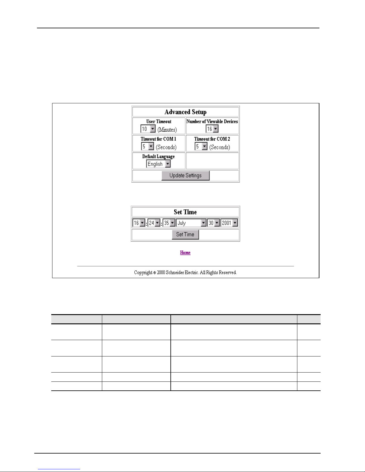
Advanced Setup
The Advanced Setup page (Figure 5–8) is accessible by the administrator password
only. This page allows administrator level users to change EGX200 timing values that
normally should not be changed. Also, you can use this page to set the EGX200 onboard clock. EGX200 parameters and corresponding values are shown in Table 5–5.
Figure 5–8: EGX200 Advanced Setup page
Table 5–5: Advanced communication setup parameters
Parameter Range of Values Description Default
User Timeout 1 to 255 minutes
Timeout for COM
Ports
Number of
Viewable Devices
Default Language English, French, Spanish The language to be displayed as the default English
Set Time Current time and date of the EGX200
3to10seconds
2 to 96 devices Number of viewable devices in the Device List 16
MaximumidletimeallowedbeforetheEGX200
ends a user's access to the web pages
Maximum time the EGX200 waits for requested
information from RS-485 daisy-chained devices
Logging Out
To log out of the EGX200 configuration session, click Home to return to the EGX200
Home page. Click Log Out to end your session.
10
5
38
© 2001 Schneider Electric All Rights Reserved
63230-314-200/A2 Appendix A—Maintenance and Troubleshooting
8/2001 Maintenance
APPENDIX A—MAINTENANCE AND TROUBLESHOOTING
MAINTENANCE
The EGX200 does not require maintenance, nor does it contain any user-serviceable
parts. If the EGX200 requires service, contact your local sales representative for help.
Refer to the Technical Support Contacts provided in the shipping carton for a list of
support phone numbers by country. Do not open the EGX200 enclosure; this will void
the product warranty agreement.
DANGER
HAZARD OF ELECTRIC SHOCK, BURN, OR EXPLOSION
• This equipment must be installed and serviced only by qualified personnel.
• Qualified persons performing diagnostics or troubleshooting that require electrical
conductors to be energized must comply with NFPA 70 E – Standard for Electrical
Safety Requirements for Employee Workplaces and OSHA Standards– 29 CFR Part
1910 Subpart S – Electrical.
Failure to follow these instructions will result in death or serious injury.
TROUBL ES HO OTING
Potential problems, possible causes, and solutions are listed in Table A–1.
Tab le A–1: Troubleshooting
Problem Possible Cause Solution
Power LED is not lit.
Ethernet link LED is
not lit.
SMS does not
connect to the
EGX200.
SMS does not go
online with devices
on EGX200.
Forgot administrator
password.
Source power is not
applied or is not stable.
LED is burned out.
Proper link is not
established.
Incorrect IP address. Enter correct IP address.
Incorrect subnet mask or
IP router address.
Incorrect network
configuration.
EGX200 not functioning
correctly or has
configuration problems.
Apply power or check power source.
Check to see if other LEDs operate properly. If they do,
contact your network administrator.
Make sure the proper cable is used and connected.
Enter correct subnet mask and/or IP router address.
Verify EGX200 receives requests (ping EGX200 by going to
DOS prompt and typing “ping” and the EGX200 IP address,
e.g., ping 199.0.62.41).
Verify that the EGX200 communication configuration
matches the SMS configuration.
Verify the device address is entered correctly in SMS.
Call your local sales representative for assistance.
© 2001 Schneider Electric All Rights Reserved
39

Appendix A—Maintenance and Troubleshooting 63230-314-200/A2
Troubleshooting 8/2001
40
© 2001 Schneider Electric All Rights Reserved

63230-314-200/A2 Appendix B—Firmware Updates
8/2001
APPENDIX B—FIRMWARE UPDATES
Due to technological improvements, the firmware your EGX200 was shipped with may
be updated periodically. We recommend periodically checking with your local sales
representative to see if an upgrade is available.
If an update becomes available, compare the updated version number with your
version number shown on the EGX200 Home page. If the update is a newer version
(has a higher version number), transfer it to your computer hard drive, taking note of
the folder in which you place it.
To use FTP to transfer the firmware upgrade into your EGX200, follow these steps:
NOTE: In this example, we will assume that you saved the EGX200 new firmware
update file into a folder called EGX, which is located on your C: drive.
1. Access DOS on your computer by selecting Start > Program > Command Prompt.
The Command Prompt screen displays, as shown in the following figures.
2. Type the drive you want to access (in this case, C:\), and press Enter.
3. Type cd (change directory) and the name of the folder containing the firmware file
(in this example, the egx folder), and press Enter. (See Figure B–1.)
Figure B–1: IdentifyingfolderwheretheEGX200firmwarefileisstored
4. At the C:\EGX prompt, type ftp and the IP address assigned to the EGX200, and
then press Enter, as shown in Figure B–2. The IP address 150.200.250.50 is used
as an example only.
NOTE: The IP address 150.200.250.50 is used as an example only.
Figure B–2: Entering FTP session
© 2001 Schneider Electric All Rights Reserved
41

Appendix B—Firmware Updates 63230-314-200/A2
8/2001
You should receive the message “Connected to [IP address],” indicating you are
now in an “ftp” session.
5. At the User [150.200.250.50: (none)]: prompt, press Enter.
6. At the Password: prompt (Figure B–3), type the administrator password (admin is
the default password until the administrator changes it).
NOTE: The IP address 150.200.250.50 is used as an example only.
Figure B–3: Password prompt
7. At the ftp prompt (Figure B–4), type send [egx#####.bin], and press Enter to
initiate the ftp transfer. The filename you enter is case-sensitive.
NOTE: ##### refers to the EGX200 firmware version number.
NOTE: The IP address 150.200.250.50 is used as an example only.
Figure B–4: File transfer completed
8. When the download is complete (Figure B–4), the ftp prompt displays again. Type
quit and press Enter to exit the FTP session.
42
© 2001 Schneider Electric All Rights Reserved

63230-314-200/A2 Appendix C—Communicating with SMS Using the EGX200
8/2001
APPENDIX C—COMMUNICATING with SMS USING the EGX200
This appendix provides instructions for using System Manager Software (SMS) to set
up a PC interface with the EGX200.
NOTE: You must be running SMS version 3.2 or higher.
To communicate with SMS, follow these steps:
1. Launch SMS.
2. Open an existing system or create a new system.
3. Add a communication connection for the EGX200.
• For the communications connection name, type a unique name for your EGX200
connection.
• For the communications driver, select “MODBUS/TCP driver.”
4. Input the EGX200 IP address in the communication connection (MODBUS/TCP).
5. After defining the communications connection, add the serial daisy-chained
devices using the EGX200 communication connection.
For more details about this process, please refer to the SMS Help option in SMS by
going to SMS > Quick Start > Quick start MODBUS/TCP device setup.
© 2001 Schneider Electric All Rights Reserved
43

Appendix C—Communicating with SMS Using the EGX200 63230-314-200/A2
8/2001
44
© 2001 Schneider Electric All Rights Reserved

63230-314-200/A2 Appendix D—Specifications
8/2001
APPENDIX D—SPECIFICATIONS
Tab le D–1: Specifications
CONTROL POWERINPUT SPECIFICATIONS
Operating Input Range
24 Vdc (±10%)
Burden, maximum 8 Watts
Isolation
1.5 Kv
ENVIRONMENTAL SPECIFICATIONS
Ambient Operating Temperature
Storage Temperature
–30° to +80°C.
–40° to +85°C.
Humidity Rating 5–95% Relative Humidity (non-condensing) at +40°C
Pollution Degree Class 2
PHYSICAL SPECIFICATIONS
Weight
Dimensions
1.5lbs.(.68Kg)
Length (7.88 in. / 200.2 mm), Width (4.81 in. / 122.2 mm),
Depth (1.07 in. / 27.2 mm)
REGULATORY/STANDARDS COMPLIANCE
Electromagnetic Interference
Radiated Emissions
Conducted Emissions
Immunity for Industrial Environments
Electrostatic Discharge (Air Discharge)
EN 55022 / FCC Class A
EN 55022 / FCC Class A
EN 61000-6-2
EN 61000-4-2
Immunity to Surge (Impulse Wave) EN 61000-4-5
Immunity to Electrical Fast Transients EN 61000-4-4
Power Frequency Magnetic Field EN 61000-4-8
Voltage Dips EN 61000-4-11
Voltage Interruptions EN 61000-4-11
Conducted Immunity EN 61000-4-6
Radiated Immunity EN 61000-4-3
Safety
USA (Miscellaneous Apparatus) UL 508
Canada (Industrial Equipment) cUL (complies with CSA C22.2, #14–M91)
Europe CE
© 2001 Schneider Electric All Rights Reserved
45

Appendix D—Specifications 63230-314-200/A2
8/2001
46
© 2001 Schneider Electric All Rights Reserved

63230-314-200/A2 Index
8/2001
INDEX
Numerics
10/100base T port (twisted pair) 4
2-wire
biasing and termination
communication 23
4-wire
biasing and termination
communication 23
26
26
A
access levels 36–37
advanced setup 38
B
baud rate, setting 15, 32
Belden 8723 cable
4-wire communication
Belden 9841 cable
2-wire communication
Belden 9842 cable
4-wire communication
biasing
2-wire configuration
4-wire configuration 26
RS-485 daisy chains 26
box contents
EGX200
3
23
23
23
26
COM port timeout 38
command prompt 41
communications
2-wire
4-wire 23
settings 15
setup parameters 38
communications settings
page
components
EGX200
configuration
2-wire
4-wire 26
RS-485 26
connections
control power
PC to EGX200 13
wiring 21
connectors
control power
DB9 25
RS-485 4
terminal block 21
control power
connection
connector 4
LED 21
wiring 21
cross-over cable 8
23
12, 31
4
26
4
4, 21
4
C
cable
Ethernet cross-over
null modem 13
clock
EGX200
COM 1
LED
COM 2
LED
COM port
RS-232
RS-485 4
© 2001 Schneider Electric All Rights Reserved
38
25
25
4
D
8
daisy chain
2-wire
4-wire 24
biasing and termination 26
connected to RS-485 port 22
maximum distances 24
data bits, setting 15
date, setting 38
DB9 connector 25
device list
setting up
24
33
47

Index 63230-314-200/A2
8/2001
devices
viewable
diagnostics
displaying
dimensions
EGX200
DIN rail
dimensions
mounting 20
dip switches 4
settings 26
DOS 41
38
35
18
18
E
EGX200
advanced setup page
application example 2
box contents 3
clock setup 38
communications settings 12, 31
components 4
description 1
dimensions 18
embedded web pages 31
firmware updates 41
home page 11, 30
installing 1
IP address 10, 29
logging into 11, 29
logging out 38
login page 30
mounting and installation 17
password administration 36
service 39
setup utility 16
specifications 45
time and date 38
timing values 38
using SMS 43
wiring 21
Ethernet
communications setup parameters
cross-over cable 8
LEDs 27
38
link LED 4
port setup 32
ports 27
system architecture example 2
F
firmware, updating 41
flow control, setting 15
H
home page 11, 30
HyperTerminal
COM port properties page
connect to page 14
connection description page 14
opening 13
using 13
15
I
installation
DIN rail mount
EGX200 1
flat surface mount 20
mounting feet 20
quick reference 7
wall/panel mount 19
IP address
entering in browser address field
20
10,
29
setting 8
L
language
setting default
LEDs
COM 1
COM 1 and COM 2 25
COM 2 4
control power 21
Ethernet 4, 27
Ethernet link 4
8
power 4
RS-485 4
levels, access 36–37
4
38
48
© 2001 Schneider Electric All Rights Reserved

63230-314-200/A2 Index
8/2001
log out, EGX200 38
logging into EGX200 29
login page 11, 30
M
maintenance 39
mode, wiring 32
mounting
DIN rail
flat surface 20
locations, typical 17
wall/panel 19
20
N
null modem cable 13
O
operation 29
quick reference 7
P
page
advanced setup
communications settings 12, 31
device list 33
diagnostics 35
home 11, 30
login 11, 30
password administration 36
parameters
advanced communication setup
communications settings 15
serial port setup 32
parity, setting 15, 32
password administration 36
password, entering 11
pinout, RS-232 25
port
10/100base T (twisted pair)
com 1 25
com 1 (RS-485) 4
com 2 25
com 2 (RS-485) 4
38
Ethernet 4, 27
Ethernet setup 32
RS-232 serial 25
selection 32
timeout values 38
power
LED
4
power supply 21
precautions, safety 5
Q
quick reference
installing and operating
7
R
router
setting
RS-232
com port
pin assignments 25
serial port 25
RS-485
device definitions address range
LED 4
serial ports 22
8
4
34
S
safety precautions 5
serial devices
identifying
38
4
serial ports
RS-232
RS-485 22
service, EGX200 39
settings
dip switches
setup
communications
Ethernet communications parame-
ters
HyperTerminal 13
IP address 8
router 8
33
25
26
15
8
© 2001 Schneider Electric All Rights Reserved
49

Index 63230-314-200/A2
8/2001
serial port parameters 32
subnet mask 8
web browser 8
setup utility
accessing
descriptions 16
entering EGX200 16
options 16
SMS, communicating with 43
specifications 45
static IP address
forcing
stop bits, setting 15
subnet mask 9
setting 8
switches
dip switch settings
13
9
4
T
technical support 39
wiring
2-wire communication
4-wire communication 23
connections 21
control power 21
mode 32
23
terminal block connector 21
termination
2-wire configuration
4-wire configuration 26
RS-485 daisy chains 26
time, setting 38
timeout
COM port
user 38
timing values, EGX200 38
troubleshooting 39
38
26
V
viewable devices 38
W
web browser
launching
using 8
10, 29
web pages
EGX200
50
31
© 2001 Schneider Electric All Rights Reserved


Ethernet Gateway EGX200 for POWERLOGIC®Systems
Bulletin No. 63230-314-200/A2
Class 3020 SS 5C 8/2001
 Loading...