

PowerLOC VLD101, VLD103 User Manual

Vehicle Location Device –
VLD100 Series
User Manual
Version: 1.2.6 May 8, 2001

Vehicle Location Device - VLD100 Series
Copyright © 2001, PowerLOC Technologies Inc.
All rights reserved. No part of the contents of this manual
can be copied, altered, or reproduced in any form without
prior written permission from PowerLOC.
L-Biz, and LSP are registered trademarks belonging to
PowerLOC Technologies Inc.
Java is a registered trademarks belonging to Sun
Microsystems.
PowerLOC reserves the right to make improvements in
the products described in this manual at any time without
prior notice. PowerLOC makes no representation or
warranties with respect to the content of this manual.
Further, PowerLOC reserves the right to make any
changes in its content without obligation to notify any
person or organization of such revisions or changes.
ii Version: 1.2.6 May 8, 2001

User Manual
Dear Customer,
Thank you for purchasing PowerLOC Vehicle Location
Device (VLD100 Series). For your safety and optimum
performance of the device, please read the instructions
in this manual carefully.
Please record the serial number, MAN and MIN codes
found on the back of the VLD Module in the space
provided below. You will need these numbers for
activation of the VLD, and for future refernces.
Unit Serial Number
This device complies with Part 15 of the FCC Rules.
Operation is subject to the following two conditions: (1)
this device may not cause harmful interference and (2)
this device must accept any interference received,
including interference that may cause undesired
operation.
WARNING!
To satisfy FCC RF exposure rquirements for mobile
transmitting devices, a minimum seperation distance
must be maintained between the antenna of this device
and persons during device operation. Operation at closer
than this distance is not recommended. For detailed
distance for each module, see Tables 5-1 and 5-2.
Version: 1.2.6 May 8, 2001 iii

Vehicle Location Device - VLD100 Series
CAUTION!
Changes or modifications not expressly approved by
PowerLOC voids the user’s authority to operate the equipment.
CAUTION!
This equipment has been tested and found to comply with the
limits for a Class B digital devices, pursuant to Part 15 of the
FCC Rules. These limits are designed to provide reasonable
protection against harmful interference in a residential
installation. This equipment generates, uses, and can radiate
radio frequency energy and, if not installed and used in
accordance with the instruction manual, may cause harmful
interference to radio communications. However, there is no
guarantee that interference will not occur in a particular
installation. If this equipment does cause harmful interference
to radio or television reception, which can be determined by
turning the equipment off and on, the user is encouraged to try
to correct the interference by one or more of the following
measures: Reorient or relocate the receiving antenna; Increase
the separation between the equipment and receiver; Consult
the dealer or an experienced Automotive/Audio technician for
help
.
CAUTION!
To prevent fire or risk hazard, do not expose the VLD unit
to rain or excessive moisture.
CAUTION!
This device should only be used for a vehicle application, and
should only be installed by authorized installers. Product
warranty is null and void if the device is not installed by an
authorized installer.
iv Version: 1.2.6 May 8, 2001

User Manual
Table of Contents
Product Description . . . . . . . . . . . . . . . . . . . .1-1
Package Contents . . . . . . . . . . . . . . . . . . . . .1-1
VLD Module . . . . . . . . . . . . . . . . . . . . . . . . .1-3
Wireless Antenna . . . . . . . . . . . . . . . . . . . .1-4
GPS Receiver . . . . . . . . . . . . . . . . . . . . . . .1-4
Wiring Harness . . . . . . . . . . . . . . . . . . . . . .1-4
Optional . . . . . . . . . . . . . . . . . . . . . . . . . . . .1-5
VLD Introduction . . . . . . . . . . . . . . . . . . . . . .1-6
Mobile VLD . . . . . . . . . . . . . . . . . . . . . . . . .1-7
Tracker Server . . . . . . . . . . . . . . . . . . . . . . .1-9
Fleet Manager (Client Software) . . . . . . . . .1-9
LSP Overview . . . . . . . . . . . . . . . . . . . . . . . .1-9
VLD101 and VLD103 . . . . . . . . . . . . . . . . .1-10
Usage . . . . . . . . . . . . . . . . . . . . . . . . . . . . . .1-11
Environment . . . . . . . . . . . . . . . . . . . . . . .1-11
Warranty . . . . . . . . . . . . . . . . . . . . . . . . . .1-11
Repair and Returns . . . . . . . . . . . . . . . . . .1-11
Introduction To Mobile GPS . . . . . . . . . . . . .2-1
Global Positioning System Overview . . . . . . .2-1
Mobile GPS Applications . . . . . . . . . . . . . . . .2-3
Asset Recovery . . . . . . . . . . . . . . . . . . . . . .2-3
Single Vehicle Tracking . . . . . . . . . . . . . . . .2-3
Fleet Management . . . . . . . . . . . . . . . . . . . .2-3
VLD Provisioning . . . . . . . . . . . . . . . . . . . . . .3-1
Provisioning Overview . . . . . . . . . . . . . . . . . .3-1
Registration . . . . . . . . . . . . . . . . . . . . . . . . .3-1
Activation . . . . . . . . . . . . . . . . . . . . . . . . . . .3-2
Software Installation and Setup . . . . . . . . . .4-1
Version: 1.2.6 May 8, 2001 v
Overview . . . . . . . . . . . . . . . . . . . . . . . . . . . .4-1
Staying Updated . . . . . . . . . . . . . . . . . . . . .4-1
Starting the Client Software . . . . . . . . . . . . . .4-2
The Client Screen . . . . . . . . . . . . . . . . . . . . .4-5
Active Map . . . . . . . . . . . . . . . . . . . . . . . . . .4-6

Vehicle Location Device - VLD100 Series
Fleet Controller . . . . . . . . . . . . . . . . . . . . . . 4-6
Message Monitor . . . . . . . . . . . . . . . . . . . . 4-8
Tool Bar . . . . . . . . . . . . . . . . . . . . . . . . . . . 4-8
Map Controller . . . . . . . . . . . . . . . . . . . . . . 4-9
Menu Bar . . . . . . . . . . . . . . . . . . . . . . . . . . 4-9
Status Bar . . . . . . . . . . . . . . . . . . . . . . . . . 4-10
Finding a vehicle . . . . . . . . . . . . . . . . . . . . 4-10
Working with Vehicle List . . . . . . . . . . . . . . 4-13
Working with Map Functions . . . . . . . . . . . . 4-14
Working with Trigger Functions . . . . . . . . . . 4-16
Stand-by Mode . . . . . . . . . . . . . . . . . . . . . 4-16
Exception Mode . . . . . . . . . . . . . . . . . . . . 4-16
Setting a Geo-Fence via Client S/W . . . 4-17
Setting the Speed Limit . . . . . . . . . . . . . . 4-17
Communicati-on with VLD . . . . . . . . . . . . 4-18
Installation Guidelines and Testing . . . . . . . 5-1
Installation Overview . . . . . . . . . . . . . . . . . . . 5-1
Installing GPS Receiver & Wireless Antenna 5-3
Installing VLD Module . . . . . . . . . . . . . . . . . . 5-4
Wiring the VLD Module . . . . . . . . . . . . . . . . . 5-6
Wiring Harness Description . . . . . . . . . . . . 5-7
I/O Connector . . . . . . . . . . . . . . . . . . . . . . . 5-9
GPS Connector . . . . . . . . . . . . . . . . . . . . 5-11
COM Connector . . . . . . . . . . . . . . . . . . . . 5-11
Auxiliary Battery Connector . . . . . . . . . . . 5-11
Optional Connections . . . . . . . . . . . . . . . . 5-11
Testing . . . . . . . . . . . . . . . . . . . . . . . . . . . . 5-12
Self-Testing . . . . . . . . . . . . . . . . . . . . . . . 5-13
Warranty Card . . . . . . . . . . . . . . . . . . . . . 5-13
Limited Warranty . . . . . . . . . . . . . . . . . . . . . 5-14
I/O Interface Examples . . . . . . . . . . . . . . . . . A-1
vi Version: 1.2.6 May 8, 2001

User Manual Product Description
Chapter 1 Product Description
Package Contents
The package you purchased includes the following
items:
• Vehicle Location Device (VLD) module
• GPS receiver
• Wireless antenna
• Wiring harness
• Alert button (Also referred to as Panic Button)
• Client Software CD
• Documentation - User Manual
Not Included, Optional Items are:
• Cigarette lighter quick connector
• Geo-Fence button
• Auxiliary battery pack
• Computer interface cable (COM) - RS232 P/N
PL038-005-01
Optional items can be purchased directly from the
Location Service Providers (LSP™), the system
installer, or PowerLOC via the Internet.
Version: 1.2.6 May 8, 2001 1-1 Package Contents
Vehicle Location Device - VLD100 Series
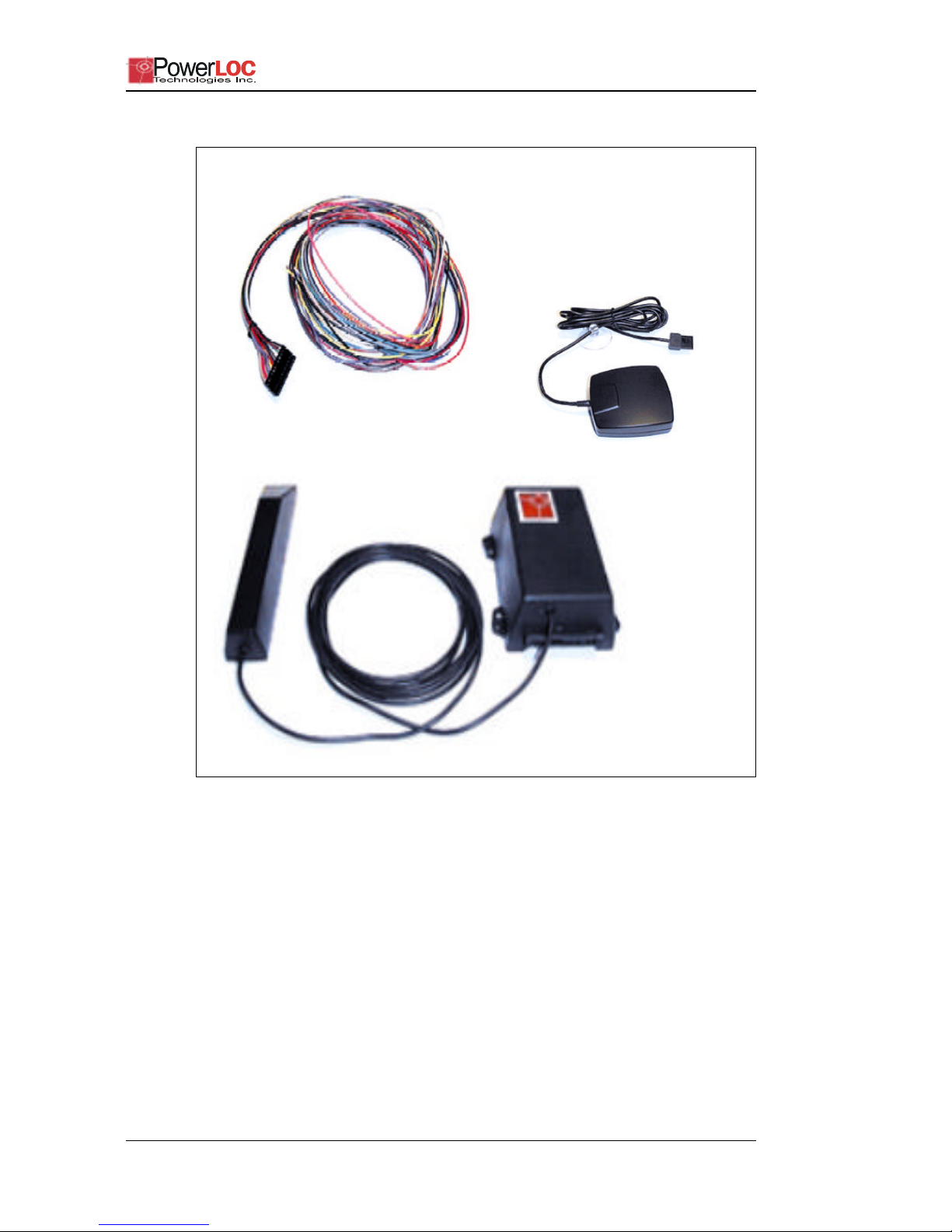
Figure 1-1VLD Module and GPS Receiver.
1. VLD module and Wireless antenna (Bottom) 2. GPS receiver
(R. Side) 3. Wiring harness (Top)
Each of the components shown in Figure1-1 are
described below:
Package Contents 1-2 Version: 1.2.6 May 8, 2001

User Manual Product Description
VLD Module
The VLD module is a small black box device
approximately 4 cm x 7 cm x 11 cm in size, which
contains electronic circuitry and a wireless modem. The
box top and bottom construction is made of Dupont Zytel
which is a super tough nylon. The key components of the
VLD module are described below:
Control Processor:
controls all operation and functionality
of the unit, tracks pre-defined events, and report
violations.
Wireless Modem and RF Module:
communicates with the
wireless carrier. The type of wireless modem used
depends on required functionality and available wireless
coverage in Customer’s region.
Power Management Circuit:
powers the VLD module, the
GPS receiver, and charges the auxiliary battery, if
applicable.
Two (2) Input Relays:
receive inputs from the vehicle –
typically Panic Alert and Set/Re-Set Geo-Fence
functions.
Two (2) Output Relays:
provide control functions in the
vehicle. For example: Open Doors, Immobilize Vehicle
and activate an Alarm buzzer functions.
I/O Connector:
12-pin connector used to connect to
vehicle’s battery and connect relays to vehicle’s
functions.
Auxiliary Battery Connector:
3-pin connector used to
connect optional external battery pack.
GPS Connector:
(serial port #1) – 9-Pin connector, used to
interface with the GPS receiver.
COM Connector:
(serial port #2) – 9-Pin connector used to
interface with a D-type RS-232 connector on a computer
for test and update purposes only.
Version: 1.2.6 May 8, 2001 1-3 Package Contents

Vehicle Location Device - VLD100 Series
NOTE: This connector is not used in vehicle
installations, unless an LCD display is attached.
If interfaced with D-Type connector, than an
interface cable (Part number PL38-005-001) is
required.
Wireless
Antenna
GPS
Receiver
The wireless antenna is used to communicate between
the VLD and the Tracker Server. Wireless connectivity is
essential for service availability. A wireless antenna may
be installed in-vehicle (internal) and out-of-vehicle
(external) configuration.
External Antenna:
securing the antenna external to the vehicle. With proper
installation, an external antenna is likely to provide the
best signal coverage.
Internal Antenna:
installation. VLD with the antenna must be carefully
installed to ensure adequate signal coverage and
distance of at least 20 cm from passengers as defined by
FCC, Part 15 regulation.
The GPS receiver consists of an antenna with a cable,
and a magnetic mount. The cable connects to the GPS
connector (serial port #1) on the VLD Module.
installation will require locating and
is attached to the VLD, and simplifies
NOTE: The GPS receiver must be installed with a clear
NOTE: If the VLD is used as an Anti-theft device, the
Wiring
Harness
Package Contents 1-4 Version: 1.2.6 May 8, 2001
The harness has a 12-pin connector which connects the
VLD to the various functions in the vehicle.
view of the sky, so that the vehicle can be
tracked by at least 4 satellites – refer to page 2-1
for additional information.
antenna will have to be concealed. Such a
mounting arrangement can impact signal
reception.

User Manual Product Description
Alert (Panic)
Button
Optional
Cigarette
Lighter
Quick
Connector
(optional)
Geo-Fence
Button
(optional)
The Alert (Panic) button allows a user to send an
emergency signal to the Tracker Server. The emergency
signal will be acted upon by a Call Center.
The optional cigarette lighter quick connector (plug) is
used for basic installation.
NOTE: Both Power and Ground wires in the wiring
harness must be connected to the quick
connector, instead of vehicle battery.
The optional Geo-Fence button allows the user to
Activate and De-Activate the Geo-Fence alarm. Any
unauthorized movement of the vehicle, such as theft or
towing, will activate an alarm signal to the LSP. The GeoFence button can be purchased separately, and installed
by the VLD installer.
Buzzer
(optional)
NOTE: PowerLOC recommends that Geo-Fence button
is installed with buzzer to provide feedback on
status (Geo-Fence Activated and Geo-Fence
De-Activated).
The buzzer can be connected to an output relay. It
provides Audio feedback for three (3) specific situations:
Long Tone - Acknowledge Alert (Panic) signal has been
received by the Tracker.
Short Tone - signals that Geo Fence has been Activated
around the vehicle.
Two short Tones - signals that GeoFence has been DeActivated from around the vehicle.
Version: 1.2.6 May 8, 2001 1-5 Package Contents

Vehicle Location Device - VLD100 Series
Auxiliary
Battery Pack
(optional)
Client
Software CD
External
Power
Supply
The optional auxiliary battery pack ensures that the VLD
is powered even when the main power supply from
vehicle’s battery is unavailable. The auxiliary battery
pack connects to the battery connector on the VLD, and
is recharged by the VLD during normal operation.This is
a standard 12V Lead-Acid battery, which can be selected
to meet size and service availability requirements.
The Client Software CD contains all the necessary
software for installation and set up of the VLD. Loading
and use of the Client Software are described in
Chapter4.
The vehicle’s battery is used to provide the VLD with a
+12V power supply and a ground connection. When the
vehicle ignition is turned Off, the VLD switches to Energy
Save mode, continues to acquire GPS positions and
perform wireless communication at a reduced rate.
To manage power consumption, consider the following
measures:
1. Install an auxiliary battery pack as a backup power
supply.
2. Disconnect the device when the vehicle is secured
and will not be used for an extended period of time.
VLD Introduction
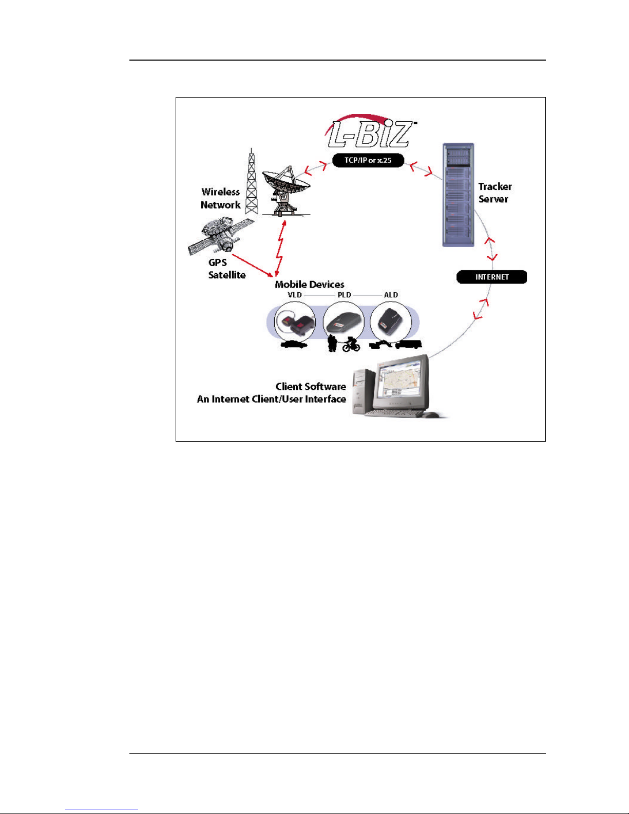
PowerLOC Technologies Inc. is an emerging leader in
the design and development of wireless Internet-enabled
tracking and location services architecture known as
L-Biz™. Figure1-2 shows the L-Biz architecture.
Vehicle location functionality consists of three components – a mobile VLD, the Tracker Server, and the webenabled Fleet Manager (Client Software). The three components are described below in detail.
VLD Introduction 1-6 Version: 1.2.6 May 8, 2001
User Manual Product Description
Figure 1-2PowerLOC’s L-Biz Architecture.
Mobile VLD
Lock/Unlock
Doors
Mobile VLD allows a user to perform two-way tracking of
a single vehicle, or a fleet of vehicles (refer to "Mobile
GPS Applications" on page 2–3) using GPS satellites.
When installed and activated by an authorized installer,
the mobile VLD allows the user to access the following
additional features:
VLD can control the driver or passenger door actuators,
for vehicle(s) with power lock(s) and will provide the
following functionality:
1. Unlock doors if the driver has been accidentally
locked out of the vehicle. This feature can be
activated by a call to the Call Center.
Version: 1.2.6 May 8, 2001 1-7 VLD Introduction

Vehicle Location Device - VLD100 Series
2. Lock doors if the vehicle has been stolen, to prevent
the thief from leaving the vehicle. This feature can be
activated by the Call Center.
Geo-Fence
Button
Immobilize
Vehicle
Alert (Panic)
Button
Geo-Fence is a virtual rectangular zone set around the
vehicle. Geo-Fence can be set (Armed) and reset
(unarmed) with a Geo-Fence button. Typically, set and
reset are followed by a unique audio tone generated by a
buzzer. If the vehicle moves outside of the set zone, a
Geo-Fence violatrioon message will be sent to the LSP.
Movment outside the zone may be due to theft, towing or
unauthorized usage. The VLD can be programmed to
send a message and/or operate functions such as flash
head lights, immobilize the vehicle etc. .
VLD can control the starter circuitry to prevent the
vehicle from being restarted. The ignition will not be
switched off when the engine is running. This feature can
be activated by the Call Center, or pre-programmed to
activate if there is a Geo-Fence violation.
If an Alert (Panic) button is installed in the vehicle, the
VLD can broadcast an emergency distress signal to the
Call Center. When the user presses the Alert (Panic)
button for 3 seconds, the distress message is
broadcasted to the Call Center. The distress message is
acknowledged by two short buzzes. The user has to predefine the nature of support needed. The Call Center can
track the distress signal to the vehicle location, speed,
and any other available signal and send help.
Geo-Fence
Remote
Activation
VLD can remotely activate the Geo-Fence feature using
a key-less remote entry control unit. Installation may
require additional components such as the control unit,
which is typical for standard alarm systems.
VLD Introduction 1-8 Version: 1.2.6 May 8, 2001

User Manual Product Description
Crash
Detection
Other
Remote
Activation
Tracker
Server
Most models of VLD have a built-in accelerometer which
can detect positive or negative accelerations, typical of
an accident. Once detected the accelerometer
information is sent to the Tracker Server and responded
too by the Call Center. The Call Center can locate the
vehicle and dispatch the necessary emergency services.
The VLD output relays can be connected to various
vehicle functions. These can be activated by dispatcher
upon user’s request. For example: Door Unlock,
Immobilize Vehicle, Engine remote Start, Flash head
lights etc.
This powerful server system manages communications
with thousands of different types of mobile VLDs. The
Tracker software is implemented in Java, and the
application is written in XML to conform to industry
standards and provide secure communications over the
Internet. The Tracker Server is owned and operated by
the LSP.
Fleet
Manager
(Client
Software)
The Fleet Manager (Client Software) is part of the L-Biz
Solution, which resides on a customer’s personal
computer (PC). It allows the user to view tracking
information over the Internet.
LSP Overview
LSPs are companies that provide the required
infrastructure needed to implement PowerLOC’s L-Biz
solutions. LSPs provide a critical role in the operation of
VLDs, and they perform the following functions:
• Sell, install and after-sale support of the VLDs
Version: 1.2.6 May 8, 2001 1-9 LSP Overview

Vehicle Location Device - VLD100 Series
• Facilitate activation and interconnection with the
wireless carrier
• Provide monthly connectivity and billing ser-
vices. The LSP Connectivity Plan is aimed to meet
your communication needs. The LSP will provide
you with detailed information about your options, and
how these reflect your tracking needs.
• Provide on-going access to information on your
vehicle via the Internet, using the Client Software
• Provide additional service such as emergency Call
Center. The Call Center services are aimed to
enhance your safety and well-being by monitoring
emergency calls, or by recognizing and informing
you if your vehicle is moved without your consent.
VLD101 and
VLD103
The VLD101 is equipped with Aeris.Net wireless Modem.
This Data Wireless Network has a very wide cellular
coverage all over North America, based on the AMP
network. The VLD101 has a limited set of functions and
is mostly suitable for security type application. More
details are available in the Product Spec.
The VLD103 use the Mobitex Data Wireless network. It is
suitable for various applications and has a wide range of
functionality. More details are available in the Product
Spec.
Table1-1 Available wireless networks and carriers for
North America
Table 1-1Available Wireless Networks and Carriers.
VLD Model
Wireless
Network
Wireless Carrier
VLD101 Aeris Aeris.Net
VLD103 Mobitex Cingular Wireless (US)
VLD103 Mobitex Rogers-AT&T (CAN)
LSP Overview 1-10 Version: 1.2.6 May 8, 2001

User Manual Product Description
Usage
Environment
Warranty
Repair and
Returns
Operating Temp. -30o C to +70o C (-22o F to +158o F).
Storage Temp. -40o C to +85o C (-40o F to +185o F).
Humidly 5% to 95% RH Non-condensing at 40oC
(104oF)
Vibration SAEJ1211 for chassis mounted device
The VLD is covered by a 1-year warranty. See section 512 for details.
Contact your LSP for repairs to your VLD and to obtain a
Return Authorization Number (RAN) to return your VLD.
Contact an authorized installer to remove and re-install
the VLD.
Version: 1.2.6 May 8, 2001 1-11 Usage

Vehicle Location Device - VLD100 Series
This page is blank
Usage 1-12 Version: 1.2.6 May 8, 2001

User Manual Introduction To Mobile GPS
Chapter 2 Introduction To Mobile GPS
Global Positioning System Overview
Global Positioning System (GPS) consists of a
constellation of 24 satellites that lie in nongeosynchronous orbits at inclinations of 55o
approximately 11,000 miles above the Earth. This
constellation, which circles the Earth once every
twelve hours, is organized into four sets of
satellites that follow each other in a total of six
circular orbits.
An observer on the Earth ‘sees’ between six and
eleven satellites at any given time when scanning
the skies 5o or more above the local horizon. Only
21 of the 24 satellites are used to provide
positioning service; the remaining three are used
as backups. This increases the availability and
reliability of GPS on a global scale.
GPS satellites are used to calculate the position of
a GPS receiver on or above the surface of the
Earth by applying simple geometry, combined with
some clever computing algorithms. These assist
the receiver to determine the correct satellites to
use, and resolve any location ambiguity that might
arise. Each satellite broadcasts its unique
navigation and identification signal that the
receiver decodes and uses for calculation
purposes.
Version: 1.2.6 May 8, 2001 2-1 Global Positioning System Overview

Vehicle Location Device - VLD100 Series
When GPS algorithms are applied, the longitude,
latitude, altitude and speed of the receiver unit can be
determined. When this information is then applied to
geophysical maps, the absolute location and speed of
the receiver unit can be determined at high level of
accuracy.
Originally developed by the US military, GPS was made
available for civilian use by the US Department of
Defense (DoD) in the early 1999s. The GPS system is
free-of-charge to use. Anyone who has a GPS receiver
can access the GPS satellites to pinpoint the receiver
location. Originally civilian usage of GPS was limited to
Coarse Acquisition (C/A) code. In May 2000 the C/A
restrictions were removed, which resulted in increased
accuracy from 30 meter (100 feet) to 3 meters (10 feet).
Accuracy depends on number of parameters such as the
number of satellites, the quality of antenna’s reception,
the vehicle’s speed and the receiver’s computing power.
For PowerLOC L-Biz Architecture, the GPS receiver on
board the vehicle determines the absolute location:
longitude, latitude, altitude and speed of the vehicle. The
VLD records and transmits this information over the
wireless network using public wireless carriers such as
Cingular Wireless (US), and Rogers AT&T (Canada).
The LSP, who hosts the Tracker Server, manages all
interfaces to the Client (yourself).
The LSP facilitates the registration and activation of the
VLDs, and provides the Client (yourself) with all
customer care, billing, and connectivity services.
The Client Software enables you to locate your vehicle
and perform additional functions (refer to page 1-3).
Similar devices are also available to track people,
animals and other assets.
Global Positioning System Overview 2-2 Version: 1.2.6 May 8, 2001
 Loading...