

Page 1
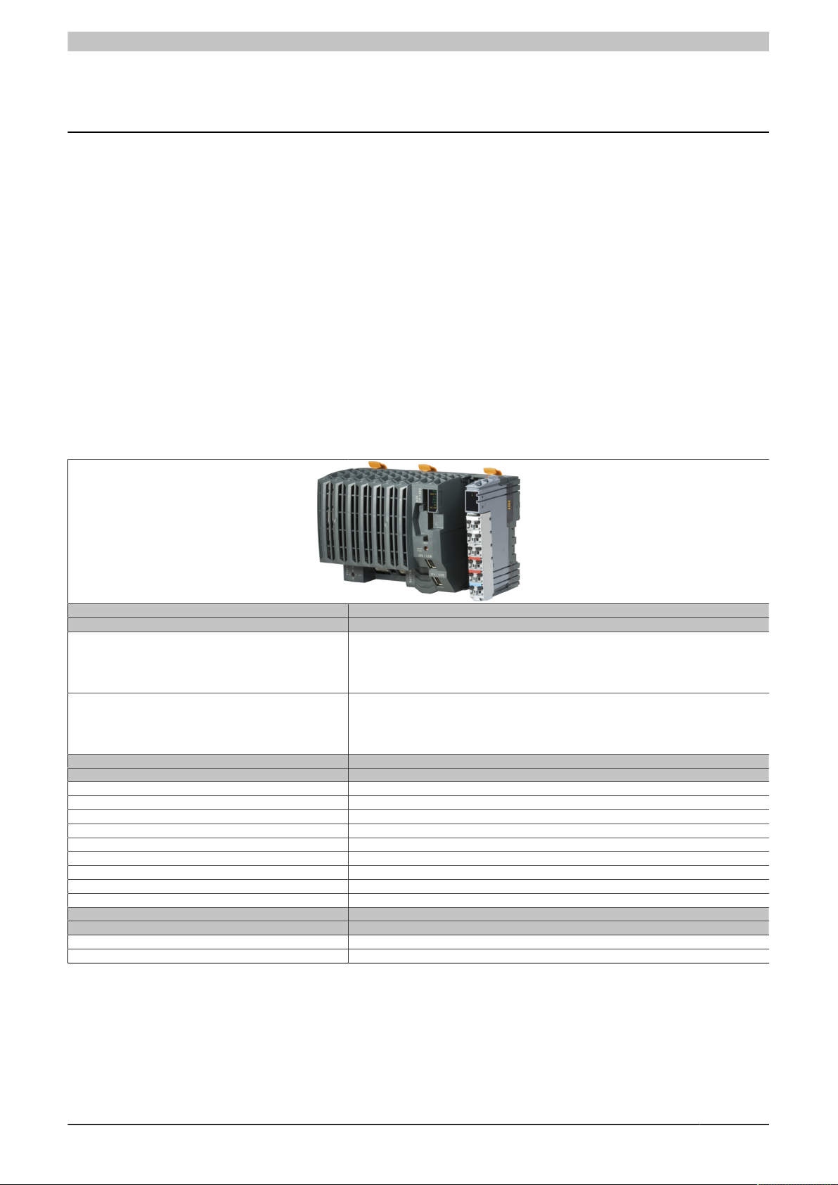
X20CP1483 and X20CP1483-1
X20CP1483 and X20CP1483-1
1 General information
The x86 100 MHz-compatible X20CP1483 is the entry-level X20 CPU. With an optimal price/performance ratio, it
has the same basic features as the larger CPUs and offers sufficient performance for most standard applications.
USB and Ethernet are included in every CPU. In addition, every CPU has a POWERLINK connection for real-time
communication.
In addition, a multi-purpose slot is provided for an additional interface module.
•
Intel x86 100 MHz-compatible with additional I/O processor
•
Onboard Ethernet, POWERLINK V1/V2 and USB
•
Modular expansion of interfaces
•
CompactFlash as removable application memory
•
Fanless
2 Order data - X20CP148x
Model number Short description
X20CP1483 X20 CPU, x86 100 MHz (Intel compatible), 32 MB DRAM, 128 kB SRAM, removable application
X20CP1483-1 X20 CPU, x86 100 MHz (Intel compatible), 64 MB DRAM, 128 kB SRAM, removable application
0CFCRD.0512E.01 CompactFlash 512 MB extended temp.
0CFCRD.2048E.01 CompactFlash 2048 MB extended temp.
5CFCRD.016G-06 CompactFlash 16 GB B&R (SLC)
5CFCRD.032G-06 CompactFlash 32 GB B&R (SLC)
5CFCRD.0512-06 CompactFlash 512 MB B&R (SLC)
5CFCRD.1024-06 CompactFlash 1 GB B&R (SLC)
5CFCRD.2048-06 CompactFlash 2 GB B&R (SLC)
5CFCRD.4096-06 CompactFlash 4 GB B&R (SLC)
5CFCRD.8192-06 CompactFlash 8 GB B&R (SLC)
0AC201.91 Lithium batteries 4 pcs., 3 V / 950 mAh button cell
4A0006.00-000 Lithium battery, 3 V / 950 mAh, button cell
X20 CPUs
memory: CompactFlash, 1 insert slot for X20 interface modules, 2 USB interfaces, 1 RS232
interface, 1 Ethernet interface 10/100BASE-T, 1 POWERLINK interface, including power supply
module, 1x terminal block X20TB12, slot cover and X20 end cover plate X20AC0SR1 (right)
included, order application memory separately!
Required accessories
CompactFlash cards
Optional accessories
Batteries
Table 1: X20CP1483, X20CP1483-1 - Order data
Data sheet V 2.38 1
Page 2
X20CP1483 and X20CP1483-1
Included in delivery
Order number Short description
4A0006.00-000 Backup battery (see also "Battery" on page 14)
- Interface module slot covers
X20AC0SR1 X20 end cover plate (right)
X20TB12 X20 terminal block, 12-pin, 24 V coding
Table 2: X20 CPUs - Content of delivery
3 X20CP148x - Technical data
Model number X20CP1483 X20CP1483-1
Short description
Interfaces 1x RS232, 1x Ethernet, 1x POWERLINK (V1/V2), 2x USB, 1x X2X Link
System module CPU
General information
B&R ID code 0xA239 0xAEC5
Cooling Fanless
Status indicators CPU function, Ethernet, POWERLINK, CompactFlash, battery
Diagnostics
Battery Yes, using LED status indicator and software
CPU function Yes, using LED status indicator
CompactFlash Yes, using LED status indicator
Ethernet Yes, using LED status indicator
POWERLINK Yes, using LED status indicator
Temperature Yes, using software register
Support
ACOPOS support Yes
Visual Components support Yes
Power consumption without memory card, interface
module and USB
Power consumption for X2X Link power supply
Power consumption
Internal I/O 0.6 W
Additional power dissipation caused by actuators
(resistive) [W]
Certifications
CE Yes
ATEX Zone 2, II 3G Ex nA nC IIA T5 Gc
UL cULus E115267
HazLoc cCSAus 244665
DNV GL Temperature: B (0 - 55°C)
LR ENV1
KR Yes
ABS Yes
EAC Yes
KC Yes
CPU and X2X Link power supply
Input voltage 24 VDC -15% / +20%
Input current Max. 2.2 A
Fuse Integrated, cannot be replaced
Reverse polarity protection Yes
X2X Link power supply output
Nominal output power 7 W
Parallel connection Yes
Redundant operation Yes
Input I/O power supply
Input voltage 24 VDC -15% / +20%
Fuse Required line fuse: Max. 10 A, slow-blow
Output I/O power supply
Nominal output voltage 24 VDC
Permissible contact load 10 A
Power supply - General information
Status indicators Overload, operating status, module status, RS232 data transfer
1)
1)
IP20, Ta (see X20 user's manual)
Industrial control equipment
Process control equipment
Class I, Division 2, Groups ABCD, T5
Humidity: B (up to 100%)
EMC: B (bridge and open deck)
Table 3: X20CP1483, X20CP1483-1 - Technical data
6 W
1.42 W
-
FTZÚ 09 ATEX 0083X
for hazardous locations
Vibration: B (4 g)
2)
3)
2 Data sheet V 2.38
Page 3

X20CP1483 and X20CP1483-1
Model number X20CP1483 X20CP1483-1
Diagnostics
RS232 data transfer Yes, using LED status indicator
Module run/error Yes, using LED status indicator and software
Overload Yes, using LED status indicator and software
Electrical isolation
I/O supply - I/O power supply No
CPU/X2X Link supply - CPU/X2X Link power
supply
Controller
CompactFlash slot 1
Real-time clock Nonvolatile, resolution 1 s, -10 to 10 ppm accuracy at 25°C
FPU Yes
Processor
Type x86 100 (compatible)
Clock frequency 100 MHz
L2 cache -
L1 cache for data and program code 16 kB
Integrated I/O processor Processes I/O data points in the background
Modular interface slots 1
Remanent variables Max. 32 kB
Shortest task class cycle time 1 ms
Typical instruction cycle time 0.09 μs
Data buffering
Battery monitoring Yes
Lithium battery At least 3 years
Standard memory
RAM 32 MB SDRAM 64 MB SDRAM
User RAM 128 kB SRAM
Interfaces
Interface IF1
Signal RS232
Variant Connection made using 12-pin terminal block X20TB12
Max. distance 900 m
Transfer rate Max. 115.2 kbit/s
Interface IF2
Signal Ethernet
Variant 1x RJ45 shielded
Cable length Max. 100 m between 2 stations (segment length)
Transfer rate 10/100 Mbit/s
Transfer
Physical layer 10BASE-T/100BASE-TX
Half-duplex Yes
Full-duplex Yes
Autonegotiation Yes
Auto-MDI/MDIX Yes
Interface IF3
Fieldbus POWERLINK (V1/V2) managing or controlled node
Type Type 4
Variant 1x RJ45 shielded
Cable length Max. 100 m between 2 stations (segment length)
Transfer rate 100 Mbit/s
Transfer
Physical layer 100BASE-TX
Half-duplex Yes
Full-duplex POWERLINK mode: No / Ethernet mode: Yes
Autonegotiation Yes
Auto-MDI/MDIX Yes
Interface IF4
Type USB 1.1
Variant Type A
Max. output current 0.5 A
Interface IF5
Type USB 1.1
Variant Type A
Max. output current 0.5 A
Interface IF6
Fieldbus X2X Link master
Electrical properties
Electrical isolation Ethernet (IF2), POWERLINK (IF3) and X2X (IF6) isolat-
ed from each other, from other interfaces and from PLC
Table 3: X20CP1483, X20CP1483-1 - Technical data
Yes
4)
5)
6)
Data sheet V 2.38 3
Page 4

X20CP1483 and X20CP1483-1
Model number X20CP1483 X20CP1483-1
Operating conditions
Mounting orientation
Horizontal Yes
Vertical Yes
Installation elevation above sea level
0 to 2000 m No limitation
>2000 m Reduction of ambient temperature by 0.5°C per 100 m
Degree of protection per EN 60529 IP20
Ambient conditions
Temperature
Operation
Horizontal mounting orientation -25 to 60°C
Vertical mounting orientation -25 to 50°C
Derating See section "Derating".
Storage -40 to 85°C
Transport -40 to 85°C
Relative humidity
Operation 5 to 95%, non-condensing
Storage 5 to 95%, non-condensing
Transport 5 to 95%, non-condensing
Mechanical properties
Note Order application memory (CompactFlash) separately
Dimensions
Width 150 mm
Height 99 mm
Depth 85 mm
Weight 300 g
Table 3: X20CP1483, X20CP1483-1 - Technical data
1) The specified values are maximum values. For examples of the exact calculation, see section "Mechanical and electrical configuration" in the X20 system
user's manual.
2) When operated at temperatures above 55°C, a derating of the nominal output power to 5 W for the X2X Link power supply must be taken into account.
3) In parallel operation, it is only permitted to expect 75% of the nominal power. It is important to make sure that all power supply units operated in parallel
are switched on and off at the same time.
4) The memory size for remanent variables is configurable in Automation Studio.
5) Minus the set remanent variables.
6) For additional information, see section "Communication / POWERLINK / General information / Hardware - IF/LS" in Automation Help.
Backup battery included in delivery
X20 end cover plate (right) included in delivery
12-pin X20 terminal block included in delivery
Interface module slot covers included in delivery
4 Data sheet V 2.38
Page 5
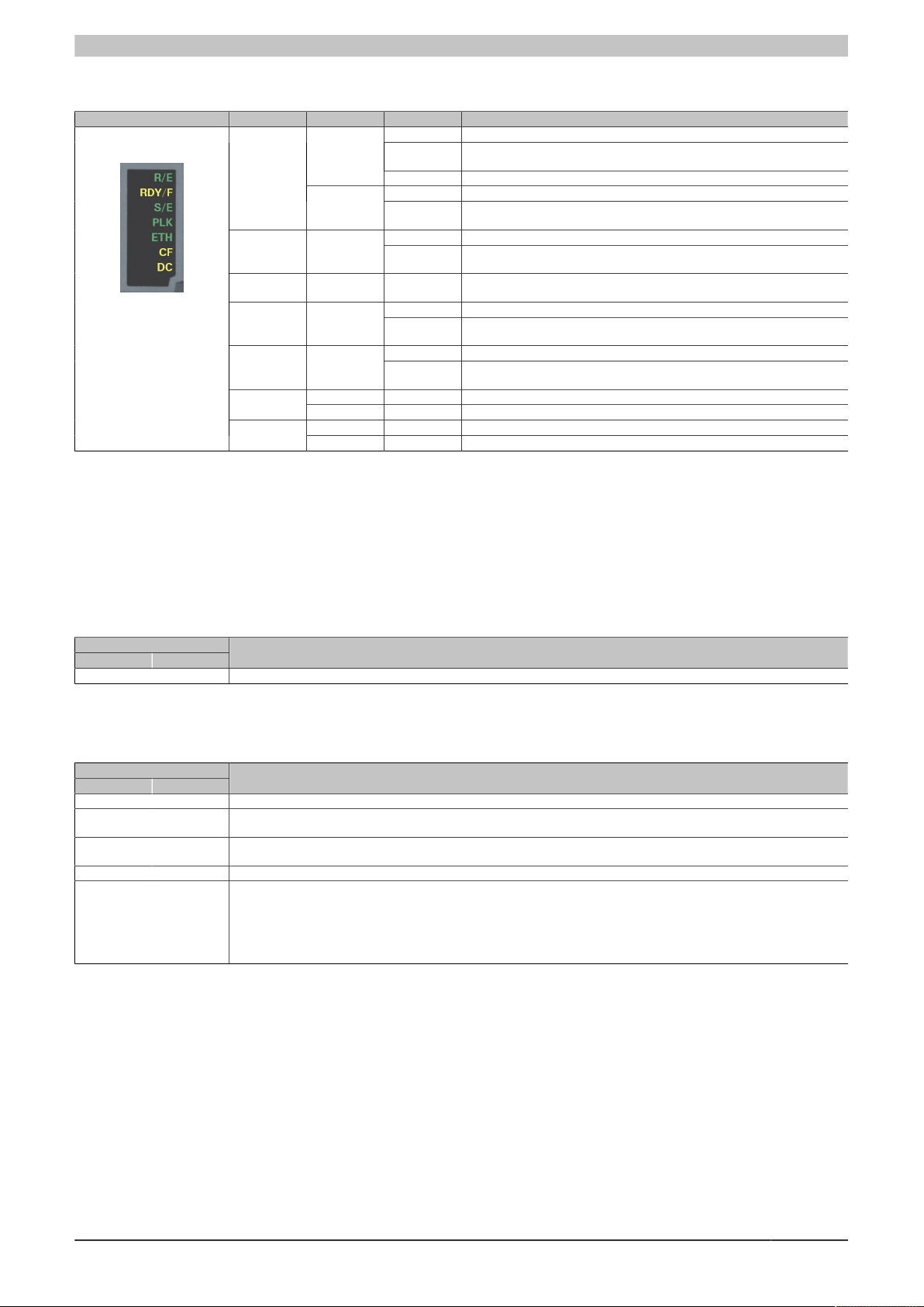
4 X20 CPUs - Status LEDs
X20CP1483 and X20CP1483-1
Figure LED Color Status Description
1) The process can take several minutes depending on the configuration.
R/E
S/E Green/Red Status/Error LED. The statuses of this LED are described in section "LED "S/
DC
Green
Red
Green On CompactFlash inserted and detectedCF
Yellow On CompactFlash read/write access
Yellow On CPU power supply OK
Red On Backup battery empty
On Application running
Blinking Boot mode system start:
Double flash Mode BOOT (during firmware update)
On SERVICE mode
Blinking The "R/E" LED blinks red and the "RDY/F" LED blinks yellow when there is a
On SERVICE or BOOT modeRDY/F Yellow
Blinking The "RDY/F" LED blinks yellow and the "R/E" LED blinks red when there is a
On A link to the POWERLINK peer station has been established.PLK Green
Blinking A link to the POWERLINK peer station has been established. The LED blinks
On A link to the peer station has been established.ETH Green
Blinking A link to the peer station has been established. Indicates Ethernet activity is
CPU initializing the application, all bus systems and I/O modules
license violation.
license violation.
E" (LED "Status/Error")" on page 5.
when Ethernet activity is taking place on the bus.
taking place on the bus.
1)
1)
4.1 LED "S/E" (LED "Status/Error")
This LED is a green/red dual LED and indicates the state of the POWERLINK interface. The LED states have a
different meaning depending on the operating mode of the POWERLINK interface.
4.1.1 Ethernet mode
In this mode, the interface is operated as an Ethernet interface.
LED "S/E"
Green Red Description
On Off The interface is operated as an Ethernet interface.
Table: LED "S/E": Interface in Ethernet mode
4.1.2 POWERLINK V1 mode
LED "S/E"
Green Red Current state of the POWERLINK node
On Off The POWERLINK node is running with no errors.
Off On A system error occurred. The type of error can be read using the PLC logbook. An irreparable problem has occurred. The system
Blinking alternately The POWERLINK managing node has failed. This error code can only occur when operated as a controlled node. This means
Off Blinking System stop. The red blinking LED indicates an error code (see "System stop error codes" on page 7).
Off Off The interface is either not active or one of the following states or errors is present:
can no longer properly carry out its tasks. This state can only be changed by resetting the module.
that the set node number lies within the range 0x01 - 0xFD.
•
The device is switched off.
•
The device is in the startup phase.
•
The interface or device is not configured correctly in Automation Studio.
•
The interface or device is defective.
Table 4: LED "S/E": POWERLINK V1 mode
Data sheet V 2.38 5
Page 6

X20CP1483 and X20CP1483-1
t
t
t
LED "S/E"
Status
green
Error
red
4.1.3 POWERLINK V2
LED "S/E"
Green Red Description
Off On The interface is in error mode (failed Ethernet frames, increased number of collisions on the network, etc.).
Blinking On If an error occurs in the following modes, then the green LED blinks over the red LED:
LED "S/E"
Green Red Description
Off Off Mode: NOT_ACTIVE
Note:
Several red blinking signals are displayed immediately after the device is switched on. These are not errors, however.
•
PRE_OPERATIONAL_1
•
PRE_OPERATIONAL_2
•
READY_TO_OPERATE
Table: LED "S/E" - Error message (interface in POWERLINK mode)
The interface is either in mode NOT_ACTIVE or one of the following modes or errors is present:
•
The device is switched off.
•
The device is in the startup phase.
•
The interface or device is not configured correctly in Automation Studio.
•
The interface or device is defective.
Flickering
(approx.
10 Hz)
Single flash
(approx. 1 Hz)
Double flash
(approx. 1 Hz)
Managing node (MN)
The network is monitored for POWERLINK frames. If a frame is not received within the configured time window (timeout), the
interface immediately enters mode PRE_OPERATIONAL_1.
If POWERLINK communication is detected before the time has elapsed, however, the MN is not started.
Controlled node (CN)
The network is monitored for POWERLINK frames. If a frame is not received within the configured time window (timeout), the
interface immediately enters mode BASIC_ETHERNET. If POWERLINK communication is detected before this time expires,
however, the interface immediately enters mode PRE_OPERATIONAL_1.
Off Mode: BASIC_ETHERNET
The interface is in mode BASIC_ETHERNET. The interface is operated in Ethernet mode.
Managing node (MN)
This mode can only be exited by resetting the controller.
Controlled node (CN)
If POWERLINK communication is detected during this mode, the interface enters mode PRE_OPERATIONAL_1.
Off Mode: PRE_OPERATIONAL_1
The interface is in mode PRE_OPERATIONAL_1.
Managing node (MN)
The MN is in "reduced cycle" mode. The CNs are configured in this mode.
Cyclic communication is not yet taking place.
Controlled node (CN)
The CN can be configured by the MN in this mode. The CN waits until it receives an SoC frame and then switches to mode
PRE_OPERATIONAL_2.
On Controlled node (CN)
If the red LED lights up in this mode, this means that the MN has failed.
Off Mode: PRE_OPERATIONAL_2
The interface is in mode PRE_OPERATIONAL_2.
Managing node (MN)
The MN starts cyclic communication (cyclic input data is not yet evaluated).
The CNs are configured in this mode.
Controlled node (CN)
The CN can be configured by the MN in this mode. A command then switches the mode to READY_TO_OPERATE.
On Controlled node (CN)
If the red LED lights up in this mode, this means that the MN has failed.
Table: LED "S/E" - Interface state (interface in POWERLINK mode)
6 Data sheet V 2.38
Page 7

LED "S/E"
200
200
1000
200
200
200
200
1000
200
200
All times in ms
Flickering
Blinking
Single flash
Triple flash
200
200
200
1000
Double flash
All times in ms
RAM error
Hardware error
150 150 150300 300 300 600 2000
150
150
300
300300600 2000600
Green Red Description
Triple flash
(approx. 1 Hz)
Off Mode: READY_TO_OPERATE
The interface is in mode READY_TO_OPERATE.
Managing node (MN)
Cyclic and asynchronous communication. Received PDO data is ignored.
Controlled node (CN)
The configuration of the CN is completed. Normal cyclic and asynchronous communication. The transmitted PDO data corresponds to the PDO mapping. However, cyclic data is not yet evaluated.
On Controlled node (CN)
If the red LED lights up in this mode, this means that the MN has failed.
On Off Mode: OPERATIONAL
The interface is in mode OPERATIONAL. PDO mapping is active and cyclic data is evaluated.
Blinking
(approx.
Off Mode: STOPPED
The interface is in mode STOPPED.
2.5 Hz)
Managing node (MN)
This mode does not occur for the MN.
Controlled node (CN)
Output data is not being output, and no input data is being provided. This mode can only be reached and exited by a corresponding command from the MN.
Table: LED "S/E" - Interface state (interface in POWERLINK mode)
X20CP1483 and X20CP1483-1
4.2 System stop error codes
A system stop error can occur due to incorrect configuration or defective hardware.
The error code is indicated by LED "S/E" blinking red. The blinking signal of the error code consists of 4 switch-on
phases with short (150 ms) or long (600 ms) duration. The error code is repeated every 2 seconds.
Error Error description
RAM error The device is defective and must be replaced.
Hardware error The device or a system component is defective and must be replaced.
Data sheet V 2.38 7
Page 8

X20CP1483 and X20CP1483-1
Top-hat rail
locking mechanism
Operating mode
switch
CompactFlash LED status indicators
IF1 - RS232
Ethernet
Station address
IF2 - Ethernet
Battery
IF4 - USB
IF5 - USB
Slot for
interface
modules
Terminal block for CPU
and I/O supply,
RS232 connection
IF6 - X2X Link
IF3 - POWERLINK
Reset button
5 LED status indicators for the integrated power supply
For a description of the various operating modes, see section "Additional information - Diagnostic LEDs" in the
X20 system user's manual.
Figure LED Color Status Description
r Green
e + r Solid red / Single green flash Invalid firmware
Off No power to module
Single flash Mode RESET
Blinking Mode PREOPERATIONAL
On Mode RUN
Off Module not supplied with power or everything OKe Red
Double flash The LED indicates one of the following states:
•
The X2X Link power supply of the power supply is overloaded.
•
I/O power supply too low
•
The input voltage for the X2X Link power supply is too low.
Off No RS232 activityS Yellow
On The LED lights up when data is being transmitted or received via the RS232
Off The X2X Link power supply is within the valid range.l Red
On The X2X Link power supply of the power supply is overloaded.
interface.
6 Operating and connection elements
8 Data sheet V 2.38
Page 9

X20CP1483 and X20CP1483-1
Reset button
7 Slot for application memory
Program memory is required to operate the CPUs. The application memory is provided in the form of a CompactFlash card. It is not included with the CPUs, but must be ordered separately as an accessory.
Information:
The CompactFlash card must not be removed during operation.
8 Operating mode switch
The operating mode switch is used to set the operating mode.
Switch position Operating mode Description
BOOT BOOT In this switch position, Boot AR is started and the runtime system can be installed via the online
RUN RUN Mode RUN
DIAG DIAGNOSE The CPU boots in diagnostic mode. Program sections in User RAM and User FlashPROM are
interface (B&R Automation Studio). User flash memory is erased only when the download begins.
not initialized. After diagnostic mode, the CPU always boots with a warm restart.
Table 5: X20 CPUs - Operating mode
Information:
A switch position other than those described here is not permitted!
9 Reset button
The reset button is located below the USB interfaces on the bottom of the housing. It can be pressed with any
small pointed object (e.g. paper clip). Pressing the reset button triggers a hardware reset, which means:
•
All application programs are stopped.
•
All outputs are set to zero.
The PLC then starts up in service mode by default. The startup mode that follows after pressing the reset button
can be set in Automation Studio.
Data sheet V 2.38 9
Page 10

X20CP1483 and X20CP1483-1
GND
+24 V I/O
+24 V I/O
GND
+24 V CP/X2X L.
+24 V CP/X2X L.
I
r
e
S
Reserved
Reserved Reserved
PS
GND
+24 VDC
+
_
+
_
I/O
Power supply
CPU/X2X Link
Power supply
10 A slow-blow
PS
GND
+24 VDC
+
_
I/O
Power supply
10 A slow-blow
Jumper
10 CPU power supply
A power supply unit is integrated in the X20 CPUs. It is equipped with a supply for the CPU, X2X Link and the internal
I/O power supply. The bus power supply and internal I/O power supply are galvanically isolated from each other.
Integrated power supply unit - Pinout
Connection example with 2 separate power supplies
Connection example with power supply and jumper
10 Data sheet V 2.38
Page 11

X20CP1483 and X20CP1483-1
I
r
e
S
TX RX
GND
1
11 RS232 interface (IF1)
The non-electrically isolated RS232 interface is designed as an online interface for communication with the programming device.
12 Ethernet interface (IF2)
IF2 is designed as a 10BASE-T/100BASE-TX interface.
The INA2000 station number of the Ethernet interface is set using the two hex switches.
For information about wiring X20 modules with an Ethernet interface, see section "Mechanical and electrical con-
figuration - Wiring guidelines for X20 modules with Ethernet cables" in the X20 user's manual.
Information:
The Ethernet interface is not suitable for POWERLINK.
When using the POWERLINK interface, the Ethernet interface is not permitted to be operated with an
IP address from the POWERLINK address range.
POWERLINK address range: 192.168.100.x
Pinout
Pin Ethernet
1 TXD Transmit data
2 TXD\ Transmit data\
3 RXD Receive data
4 Termination
5 Termination
6 RXD\ Receive data\
Shielded RJ45
7 Termination
8 Termination
PinoutInterface
Data sheet V 2.38 11
Page 12

X20CP1483 and X20CP1483-1
1
13 POWERLINK interface (IF3)
POWERLINK V1
Switch position Description
0x00 Operation as managing node.
0x01 - 0xFD Node number of the POWERLINK node. Operation as controlled node.
0xFE - 0xFF Reserved, switch position not permitted
POWERLINK V2
Switch position Description
0x00 Reserved, switch position not permitted.
0x01 - 0xEF Node number of the POWERLINK node. Operation as a controlled node (CN).
0xF0 Operation as a managing node (MN).
0xF1 - 0xFF Reserved, switch position not permitted.
Ethernet mode
Starting with Automation Studio Version V2.5.3 and with Automation Runtime V2.90, the interface can be operated
as an Ethernet interface.
The INA2000 station number can be set using the B&R Automation Studio software.
Pinout
For information about wiring X20 modules with an Ethernet interface, see section "Mechanical and electrical configuration - Wiring guidelines for X20 modules with Ethernet cables" in the X20 user's manual.
PinoutInterface
Shielded RJ45
Pin Ethernet
1 RXD Receive data
2 RXD\ Receive data\
3 TXD Transmit data
4 Termination
5 Termination
6 TXD\ Transmit data\
7 Termination
8 Termination
12 Data sheet V 2.38
Page 13

X20CP1483 and X20CP1483-1
Ambient temperature [°C]
-25
0
5
7
40 45 50 55
Mounting orientation:
Horizontal
Vertical
Nominal output power
[W]
4
60
14 USB interfaces (IF4 and IF5)
IF4 and IF5 are non-electrically isolated USB interfaces. The connection is made using a USB 1.1 interface.
The USB interfaces can only be used for devices approved by B&R (e.g. floppy disk drive, DiskOnKey or dongle).
Information:
•
USB interfaces cannot be used for online communication with a programming device.
•
Only devices isolated from GND can be connected to the USB interfaces.
•
Current-carrying capacity is listed in the technical data.
15 Slots for interface modules
The CPUs have one or three slots for interface modules.
Different bus or network systems can be flexibly integrated into the X20 system by selecting the appropriate inter-
face module.
16 Overtemperature cutoff
To prevent damage, a shut-off/reset is triggered on the CPU when the processor reaches 100°C.
The following errors are entered in the logbook:
Error number Error description
9204 WARNING: System halted because of temperature check
9210 WARNING: Boot by watchdog or manual reset
Table 6: X20 CPUs - Logbook entries after overtemperature cutoff
17 Derating
There is no derating when operated below 55°C. Above 55°C, the nominal output power for the X2X Link power
supply must be reduced to 5 W.
Data sheet V 2.38 13
Page 14

X20CP1483 and X20CP1483-1
18 Battery
X20 CPUs are equipped with a lithium battery. The lithium battery is located in a separate compartment and
protected by a cover.
Backup battery data
Order number
4A0006.00-000
0AC201.91
Short description Lithium battery, 3 V / 950 mAh, button cell
Storage temperature -40 to 85°C
Storage time Max. 3 years at 30°C
Relative humidity 0 to 95% (non-condensing)
The following areas are buffered:
•
Remanent variables
•
User RAM
•
System RAM
•
Real-time clock
Battery monitoring
The battery voltage is checked cyclically. The cyclic load test of the battery does not considerably shorten its service
life; instead, it gives an early warning of weakened buffer capacity.
Status information "Battery OK" is available from system library function "BatteryInfo" and the CPU's I/O mapping.
1 pcs.
4 pcs.
Replacement interval for battery
The battery should be replaced every 4 years. The replacement intervals recommended by B&R reflect the batteries' average service life and operating conditions. They do not correspond to the maximum buffer duration!
Important information about the battery exchange
The product design allows the battery to be changed when the power to the PLC is switched off as well as when
the power to the PLC is switched on. In some countries, safety regulations do not allow batteries to be changed
while the module is switched on. To prevent data loss, the battery must be changed within 1 min when the power
is switched off.
Warning!
The battery is only permitted to be replaced by a Renata CR2477N battery. The use of another battery
may present a fire or explosion hazard.
The battery can explode if handled improperly. Do not recharge, disassemble or dispose of the battery
in fire.
Procedure for replacing the battery
1. Perform electrostatic discharge at the top-hat rail or at the ground connection (do not reach into the power
supply unit!)
2. Remove the cover for the lithium battery. Do this by sliding it down and away from the CPU.
Figure 1: X20 CPUs - Remove lithium battery cover
3. Push the empty battery out of the holder.
14 Data sheet V 2.38
Page 15

X20CP1483 and X20CP1483-1
4. It is important to ensure that the new battery is not handled with moist or greasy fingers. Plastic tweezers can
also be used. Do not touch the battery with pliers or metal tweezers → short circuit!
5. To insert the battery into the holder, place it with the "+" side up on the right part of the battery holder. Then
press the battery into the battery holder.
6. Replace the cover.
Information:
Lithium batteries are hazardous waste! Used batteries should be disposed of in accordance with applicable local regulations.
Data sheet V 2.38 15
Page 16

X20CP1483 and X20CP1483-1
19 Programming the system flash memory
General information
In order for the application project to be executed on the CPU, the Automation Runtime operating system, the
system components and the application project must be installed on the CompactFlash card.
Creating a CompactFlash using a USB card reader
The easiest way to perform an initial installation is by creating a fully programmed CompactFlash card using a
USB card reader.
1. Creating and configuring a project in Automation Studio
2. In Automation Studio, select Tools / Create CompactFlash
3. In the dialog box that opens, select a CompactFlash card and then generate it
4. Insert the finished CompactFlash into the CPU and turn on the CPU's supply voltage
5. CPU booting
For details about commissioning: See help system under "Automation Software / Getting Started"
Installation over an online connection
The CPUs are delivered with a default B&R Automation Runtime system (with limited functions) already installed.
This runtime system is started in Boot mode (operating mode switch in the BOOT position or no CompactFlash /
invalid CompactFlash inserted). It initializes the Ethernet interface and onboard serial RS232 interface, making it
possible to download a new runtime system.
1. Insert the CompactFlash card and switch on the power to the CPU. When the switch is in the BOOT position,
a new or invalid CompactFlash card starts the CPU with the default B&R Automation Runtime system.
2. Establish a physical online connection between the programming device (PC or industrial PC) and the CPU
(e.g. over an Ethernet network or the RS232 interface).
3. Before you can establish an online connection via Ethernet, the CPU must be assigned an IP address. In
Automation Studio, select Settings from the Online menu and then click on the Browse targets button to
search for B&R target systems on the local network. The CPU should appear in the list. If the CPU has not
already received an IP address from a DHCP server, right-click on it and select Set IP parameters from the
shortcut menu. All necessary network configurations can be made on a temporary basis in this dialog box
(should be identical to the settings defined in the project).
4. Configure online connection in B&R Automation Studio. For details about the configuration: See help system
under "Automation Software / Communication / Online communication"
5. Start the download procedure by selecting the Services command from the Project menu. Then select Trans-
fer Automation Runtime from the pop-up menu. Now follow the instructions provided by B&R Automation
Studio.
20 General data points
This CPU is equipped with general data points. These are not CPU-specific; instead, they contain general information such as system time and heat sink temperature.
General data points are described in section "Additional information - General data points" in the X20 system user's
manual.
16 Data sheet V 2.38
 Loading...