

Page 1

PowerLine
™
Electric Cutter
Installation, Operating and Maintenance Instructions
PowerLine Models PL2620, PL2120 and PL2100
WARNING! This machine contains a powered cutting knife which can cause serious or even fatal injury.
Never connect power to the machine until you are ready to set up and operate the electric cutter. The
AC outlet must be nearby and not blocked. To prevent injury, never place hands or arms under the cutting blade, do not operate the machine with any covers removed or safety features disabled, and cut
only paper materials. The front blade guard must be in the lowered position before the clamp or blade
will operate. Before attempting any maintenance procedure, be sure power is disconnected and locked
out.
1.0 Introduction
Thank you for selecting the intimus®PowerLine Electric Cutter. PowerLines are designed to provide a high level of safety,
accuracy, flexibility, and ease of operation. Each component has been engineered to perform reliably and is 100% factory
tested to ensure years of quality service.
We recommend that you familiarize yourself with the cutter by carefully reading this manual. Reading and thoroughly
understanding this manual will help you avoid the most common operational problems and help eliminate operational
errors.
PowerLine Operating Instructions
1
Specifications
Functional
Cut Length x Width (behind blade):
21" EC . . . . . . . . . . . . . . . . . . .21" x 21"
26" EC . . . . . . . . . . . . . . . . . . .26" x 26"
Cut Height:
2 7/8" Maximum
Physical
Weight:
2100 EC . . . . . . . . . . . . . . . . . . .697 lbs.
2120 EC . . . . . . . . . . . . . . . . . . .716 lbs.
2600 EC . . . . . . . . . . . . . . . . . . .796 lbs.
Shipping Weight:
2100 EC . . . . . . . . . . . . . . . . . . .720 lbs.
2120 EC . . . . . . . . . . . . . . . . . . .739 lbs.
2600 EC . . . . . . . . . . . . . . . . . . .819 lbs.
Color:
. . . . . . . . . . . . . . . . . . . . . . . . . .Gray
Dimensions:
21" EC 33 3/4"W x 50 3/4"H x 42 3/4"D
26" EC 38 3/4"W x 50 3/4"H x 47 3/4"D
Electrical
AC Voltage: . . . . . . . . . . . . . . . . . .220/240VAC
Load Current: . . . .(PL2620, PL2120) 16 Amps
. . . . . . . . . . . . . . .(PL2100) 9 Amps
Optional
Side Tables
Table of Contents
1.0 Introduction . . . . . . . . . . . . . . . . . . .Page 1
2.0 Nomenclature . . . . . . . . . . . . . . . . .Page 2
3.0 Controls . . . . . . . . . . . . . . . . . . . . . .Page 3
4.0 Installation . . . . . . . . . . . . . . . . . . . .Page 4
5.0 The Back Gauge . . . . . . . . . . . . . . .Page 6
6.0 Operation . . . . . . . . . . . . . . . . . . . . .Page 6
7.0 Maintenance . . . . . . . . . . . . . . . . . .Page 7
8.0 Troubleshooting . . . . . . . . . . . . . . . .Page 12
Parts Diagrams and Parts Lists . . . . . . . . . . .Page 14
Wiring Diagrams 1 & 2 . . . . . . . . . . . . . . . .Page 20
Serial Number
_______________________________________
Page 2

2.0 Nomenclature
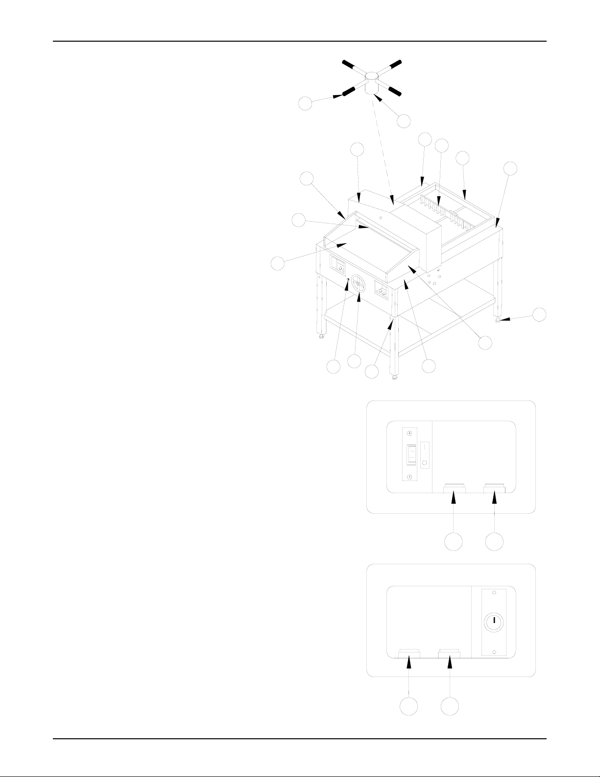
1. Chassis - Houses the electrical and mechanical components.
2. Stand - Consists of legs and shelves. The stand can be separated from the chassis.
3. Back Gauge Handwheel - Moves the back gauge to the required cutting position.
4. Right Switch Panel - Contains key switch, clamp switch, and blade switch. There is no clamp switch on Model PL2100.
5. Left Switch Panel - Model PL2100 contains On/Off toggle switch, reset switch, and blade switch. Models PL2160 and
PL2120 contains On/Off toggle switch, reset switch, and clamp/blade switch.
6. Ready Light - Amber light indicates when safety conditions are met and the machine is ready for the next cutting cycle.
7. Paper Guides - Guides paper and maintains paper position.
8. Rear Safety Cover - Fixed cover over the rear deck.
9. Back Gauge - Controls the movement of paper through the cutting area.
10. Knife - Honed steel blade provides cutting action.
11. Clamp - Secures paper during the cutting process.
12. False Clamp - Can be attached to the bottom of the permanent clamp.
13. Cutting Stick - Protects the knife edge at the bottom of the cutting cycle.
14. Leg Levelers - Adjustable feet ensure a level cutting surface.
15. Storage Shelf - Front and rear shelves for operator convenience.
16. Fuseholder - One fuseholder (located under the front portion of the chassis) contains a replaceable power fuse.
17. Circuit Breakers - Located under the front portion of the chassis.
18. Shroud - Housing for the blade and clamp drive components.
19. Serial Label - Identifies the serial number, electrical ratings, and agency approvals.
20. Line Cord - Connects the electric cutter to the AC power source.
21. Blade Adjustment - Compensates for blade wear/sharpening.
22. Side Tables - Optional accessories to add working surface area to one or both sides.
23. Back Gauge Lock Knob - Prevents movement of the back gauge when tightened clockwise.
24. Viewing Window - Provides view of back gauge position.
25. Clamp Handle Assy. (PL2100 Only) - Raises and lowers the clamp.
26. Front Safety Cover - Interlocked front deck cover.
PowerLine Operating Instructions
2
21
4
10
3
23
24
26
6
18
7
19
8
9
2
25
20
5
17
16
15
1
11 12 13
Page 3
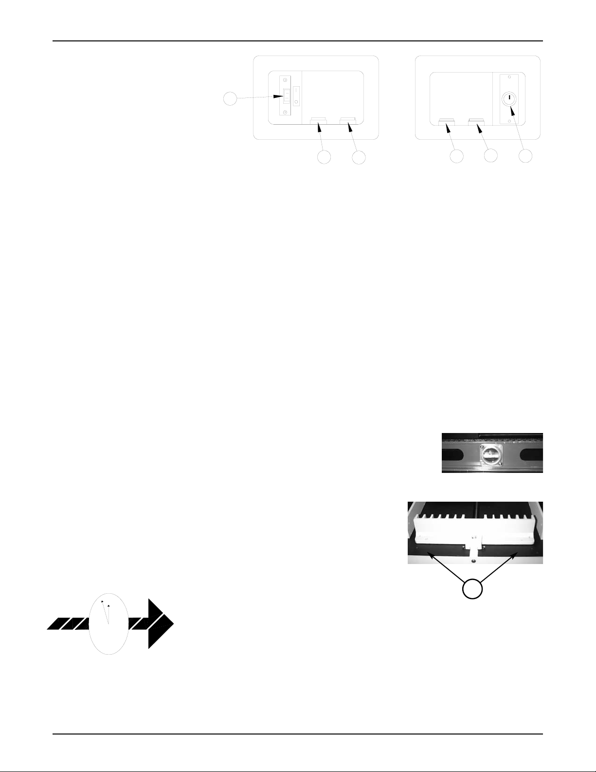
3.0 Controls
1. AC power on/off toggle switch Controls power to all circuits. The
switch bracket allows insertion of a
lock to prevent power activation of
the electric cutter.
2. Reset switch - Resets the blade and
clamp circuits for the next cutting
operation after the blade and clamp
have returned to the up position.
The ready light will come on when safety conditions are met.
3. Clamp/Blade switch - When pressed simultaneously with the clamp switch (in the right switch panel), the clamp will
travel independently of the blade to the clamping position. When pressed simultaneously with the blade switch (in the
right switch panel), both the clamp and blade will cycle through the cutting process. The PL2100 has only a blade
switch. The clamp is manually activated.
4. Blade switch - When pressed simultaneously with the Blade/Clamp switch (in the left switch panel), both the clamp and
blade will cycle through the cutting process.
5. Clamp switch - When pressed simultaneously with the Blade/Clamp switch (in the left switch panel), the clamp will
travel independently of the blade to the clamping position. The PL2100 does not contain this switch as the clamp has a
manual crank.
6. Key switch - Controls power to the blade and clamp. The key can be removed to prevent operation of the blade and
clamp. The Key switch only controls power to the blade as the clamp has a manual crank.
4.0 Installation
WARNING! To prevent serious personal injury, always use a mechanical lifting device, such as a fork lift
or pallet jack, to move the machine or to separate the chassis from the frame.
NOTE: Place the cutter on a flat, level foundation sufficient to support its weight. Be sure to allow adequate work
space on all sides of the cutter.
4.1 Leveling the Machine
Level the cutter (check the top surface in two planes) by adjusting the leg leveler in the bottom
of each stand leg. Turn the leg leveler clockwise to shorten the leg length. Turn the leg leveler
counterclockwise to increase the leg length.
4.2 Releasing the Back Gauge
To prevent shipping damage, the back gauge is locked in place by two thumb screws
located near the ends of the top rear surface of the back gauge. Remove these screws
before operating the electric cutter. To do so, first remove the rear safety cover by
removing the hex head socket screws holding the cover to the rear of the shroud and
the decks. Remove the two thumb screws that secure the back gauge to the deck surface and reattach the safety cover.
4.3 False Clamp
The false clamp, made from clear polycarbonate, is used to reduce bruising (marking) carbonless paper. It is not necessary to use the false clamp when cutting standard paper
stock. Use of the false clamp affects the minimum cutting distance. When installed, the
minimum cutting distance is 2.37". When not installed, the minimum cutting distance is
1.37". Section 6.0, Operation, includes the false clamp set up information. The false
clamp is held in place by four (three on the 21" EC) 10-32 flat head hex socket screws.
To install the false clamp, proceed as follows:
1. Turn the on/off toggle switch, located in the left switch panel, to off.
2. Turn the key switch, located in the right switch panel, to off (key vertical).
3.
Locate the position of the screws on the bottom of the false clamp. Install and tighten the screws.
PowerLine Operating Instructions
3
Left
Right
4
6
5
1
3
2
1
12
Short Cut
When cutting carbonless paper,
install the false clamp to help
prevent bruising and marking.
Page 4
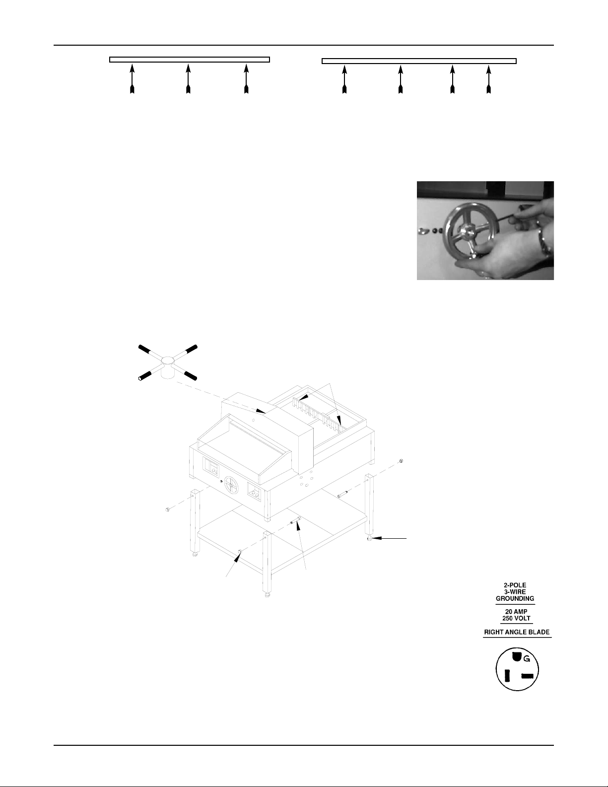
4.4 Installing the Handwheel
To help prevent shipping damage, the back gauge handwheel to your PowerLine cutter hasnot been installed. A 5/32" Hex
key wrench has been included so that the handwheel can be installed on the shaft that extends from the front center of the
machine. Two handwheel set screws must be securely tightened so that the handwheel will not freely turn on the shaft. To
install the handwheel:
1. Located the shaft that protrudes from the front center of the machine.
2. Slide the handwheel onto the shaft so that one of the set screws is aligned over the
flat surface on the shaft. Position the handwheel so that it will not rub against the
machine chassis. This is achieved when the end of the shaft is even with the outer
surface of the handwheel inner hub.
3. When the handwheel is properly positioned, securely tighten each set screw against
the shaft. You may use a commercial thread locking glue to secure the set screws in
place.
4.4 Separating the Stand and Chassis
To separate the chassis from the stand, remove the carriage bolt and acorn nut from the top of each stand leg. Lift the chassis from the stand using a mechanical lifting device. To reassemble the stand and chassis, lower the chassis onto the stand
and install the carriage bolt and acorn nut through each stand leg.
4.5 Power Requirements
The electric cutter is equipped with a 20 Amp power plug (NEMA #6-20P). This cutter requires an 20
Amp circuit with a 20 Amp receptacle (NEMA #6-20R). Have a qualified electrician install the appropriate branch circuit and receptacle.
4.6 Optional Side Tables
To install the optional side tables, simply align the holes in the tables with the screw holes in the machine frame. Install and
tighten the provided screws.
PowerLine Operating Instructions
4
26" False Clamp Screw Location21" False Clamp Screw Location
ACORN NUT (4)
CARRIAGE BOLT (4)
LEG LEVELER (4)
BACK GAUGE LOCKING SCREWS (2)
Page 5
5.0 The Back Gauge
The back gauge can be positioned to any location from 1.37" (2.37" with the false clamp installed) to 26" (21" for the 21"
Electric Cutter). The position of the back gauge is displayed through a viewing window located on the left side of the front deck.
The back gauge is positioned by rotating the handwheel located on the front of the machine. Rotating the handwheel
counter-clockwise moves the back gauge away from the cutting area. Rotating the handwheel clockwise moves the back
gauge closer to the cutting area.
To prevent the back gauge from moving after it is set to the cutting position, rotate the thumb screw, located to the left of
the handwheel, clockwise. Turn the thumb screw counter-clockwise before repositioning the back gauge. Do not loosen the
thumb screw more than 1/2 turn, as it may disengage from the locking mechanism.
NOTE: When positioning the back gauge for a longer cut (toward the rear), always go past the desired position, (about
1/4") then forward (toward the front) to the desired position. This will ensure accurate positioning of the back gauge.
6.0 Operation
WARNING! This machine contains a powered cutting knife which can cause serious or even fatal injury.
Never connect power to the machine until you are ready to set up and operate the electric cutter. To prevent injury, never place hands or arms under the cutting blade, do not operate the machine with any
covers removed or safety features disabled, and cut only paper materials.
Before plugging in the Electric Cutter power cord, be sure the following conditions have been met:
1. All safety covers are in place.
2. No objects are resting below the cutting area or on the rear decks.
3. The back gauge locking screws have been removed.
4. A 20 Amp branch circuit is available.
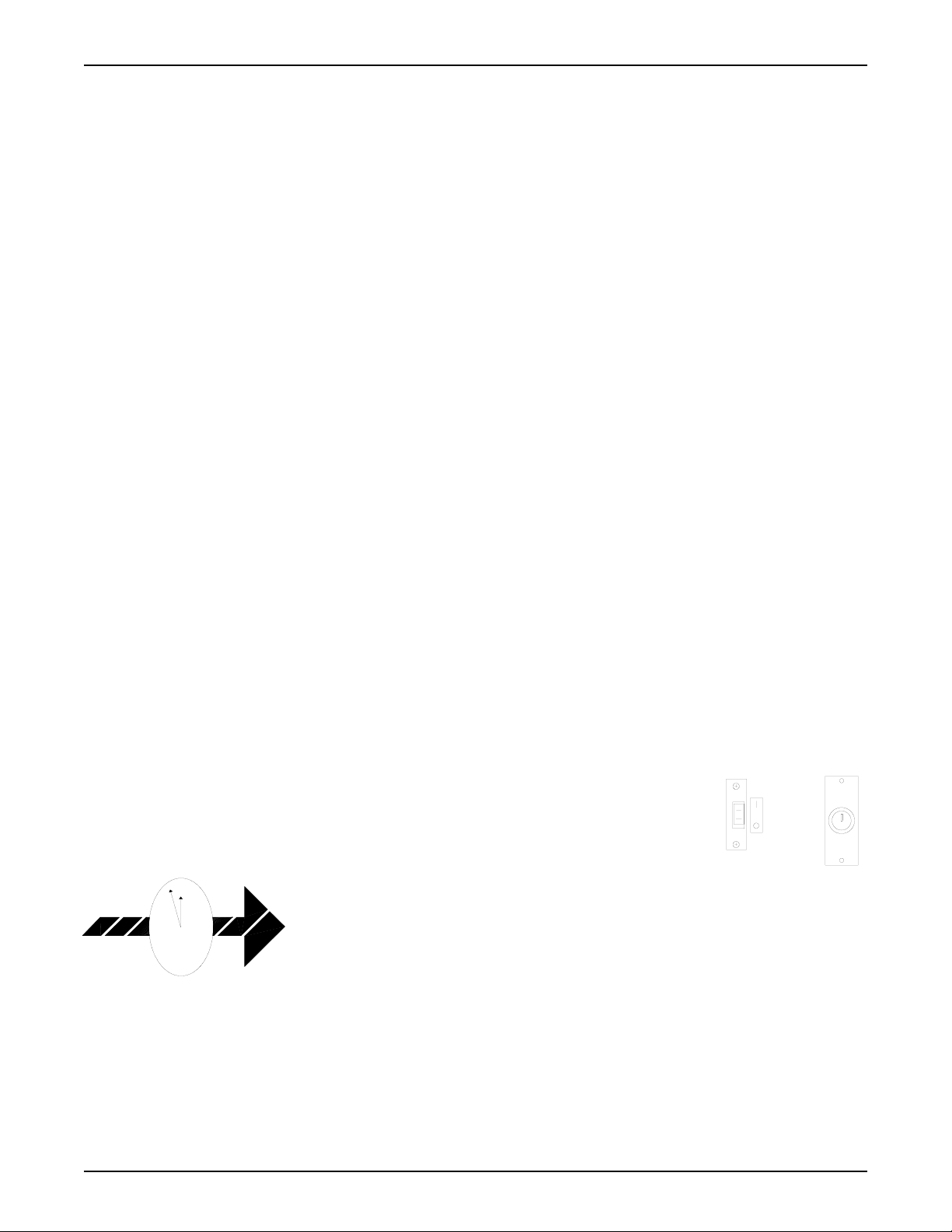
5. The On/Off toggle switch is off and that the key switch is off (key vertical).
6.1 Supply Power to the Electric Cutter
1. Plug the power cord into a 220VAC 20 Amp outlet.
2. Turn the On/Off toggle switch, (located in the left switch panel) to the on position. The cutting line lights illuminate
when power is supplied.
3. Insert the key into the key lock switch (located in the right switch panel) and turn the key to the on position.
6.2 Cutting Procedure for Models PL2620 and PL2120
1. While observing the analog scale, move the back gauge to the required cutting position.
Turn the back gauge lock knob clockwise to lock the back gauge in position. (See Section 5.0)
2. Slide the paper stock (maximum height 2 7/8") under the blade and clamp. Position the
stock against the back gauge and against either the left or right paper guide. Lower the
front safety cover.
NOTE: The front safety cover must be in the lowered position before the blade or
clamp will operate.
3. Press the reset switch located in the left switch panel. If all safety conditions are met,
the amber colored ready light will illuminate indicating that the machine is ready to cut.
4. The clamp and blade can be operated simultaneously or independently. To operate
them simultaneously, press the clamp/blade switch (located in the left switch panel) and
the blade switch (located in the right switch panel) at the same time. Hold the switches
down until the blade has cut through the stock, then release the switches. The blade and
clamp will automatically return to the up position. To operate the clamp and blade independently, the clamp must be
lowered first. To lower the clamp press, the blade/clamp switch (located in the left switch panel) and the clamp switch
(located in the right switch panel) at the same time. Release the switches when the paper stock is clamped. To cut the
PowerLine Operating Instructions
5
OFF
On/Off Toggle Switch
Key Switch
12
Short Cut
For the most accurate cuts, make
sure the paper stack is firmly
against the left or right guide.
Page 6
stock, press the clamp/blade switch and the blade switch (located in the right switch panel) at the same time. Hold the
switches down until the blade has cut through the stock, then release the switches. The blade and clamp will automatically return to the up position.
6.3 Cutting Procedure for Model PL2100
1. While observing the analog scale, move the back gauge to the required cutting position. Turn the back gauge lock knob
clockwise to lock the back gauge in position.(See Section 5.0)
2. Slide the paper stock (maximum height 2 7/8") under the blade and clamp. Position
the stock against the back gauge and against either the left or right paper guide. Lower
the front safety cover.
NOTE: The front safety cover must be in the lowered position before the blade or
clamp will operate.
3. Rotate the clamp handle assembly clockwise to lower the clamp on to the paper
stock. Firmly tighten the clamp to secure the stock.
4. Press the reset switch located in the left switch panel. If all safety conditions are met,
the amber colored ready light will illuminate indicating that the machine is ready to cut.
5. Press the blade switches (located in each switch panel) at the same time and hold them down until the blade cuts through
the stock. Release the blade switches to allow the blade to return to the up position.
6. Turn the clamp handle assembly counter-clockwise to release the stock.
7.0 Maintenance
WARNING! This machine contains a powered cutting knife which can cause serious or even fatal injury.
Never connect power to the machine until you are ready to set up and operate the electric cutter. To
prevent injury, never place hands or arms under the cutting blade, do not operate the machine with any
covers removed or safety features disabled, and cut only paper materials. Before attempting any maintenance procedure, be sure power is disconnected and locked out.
7.1 Blade Removal
WARNING! The cutting blade is extremely sharp. Serious bodily harm can result from mishandling.
NOTE: To prevent dulling the knife, do not let the knife edge contact any surface except the cutting surface or blade
carrier.
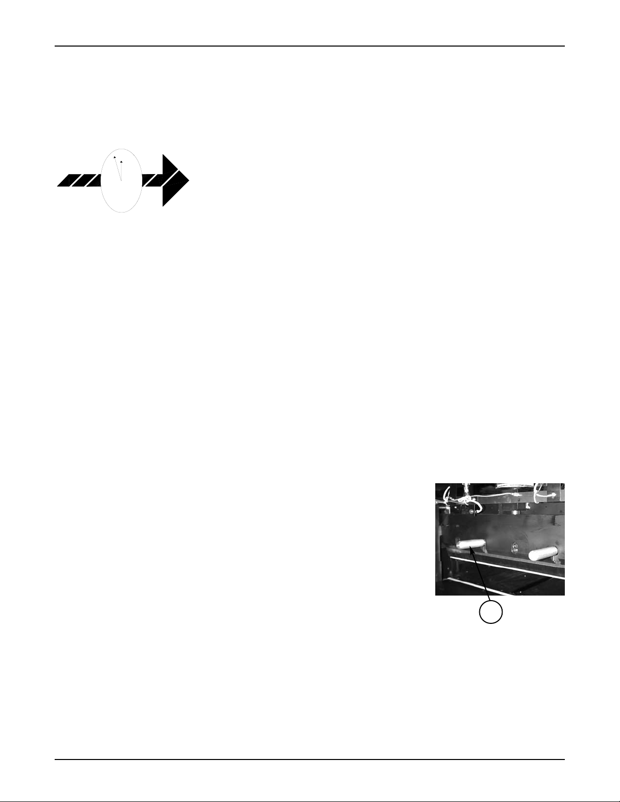
1. Activate machine power. Lower the cutting blade as if you are cutting paper. Turn off
the On/Off toggle switch when the blade contacts the cutting stick. Turn the key
switch to the “OFF” position (key vertical). Raise the front safety cover.
NOTE: The front safety cover must be in the lowered position before the blade or
clamp will operate.
2. Remove the far right blade retaining screw.
CAUTION: Do not operate the blade or clamp with the blade holder tools
attached to the blade. Extensive equipment damage can occur.
3. Turn the On/Off toggle switch and key switch to the “ON” position so that the blade and clamp will return to the up
position. Turn the key switch to the OFF position (key vertical). Remove the two center blade retaining screws. Install
and securely tighten the blade holder tools.
WARNING! When you loosen the blade holder tools, the blade will be free to fall from the carrier. Make
sure you have a firm grip on the blade holder tools.
4. Raise the front safety cover. Loosen the remaining blade retaining screws. Loosen the blade holder tools and carefully
lower the blade from the blade carrier.
PowerLine Operating Instructions
6
12
Short Cut
When cutting carbonless paper,
install the false clamp to help prevent bruising and marking.
1
Page 7
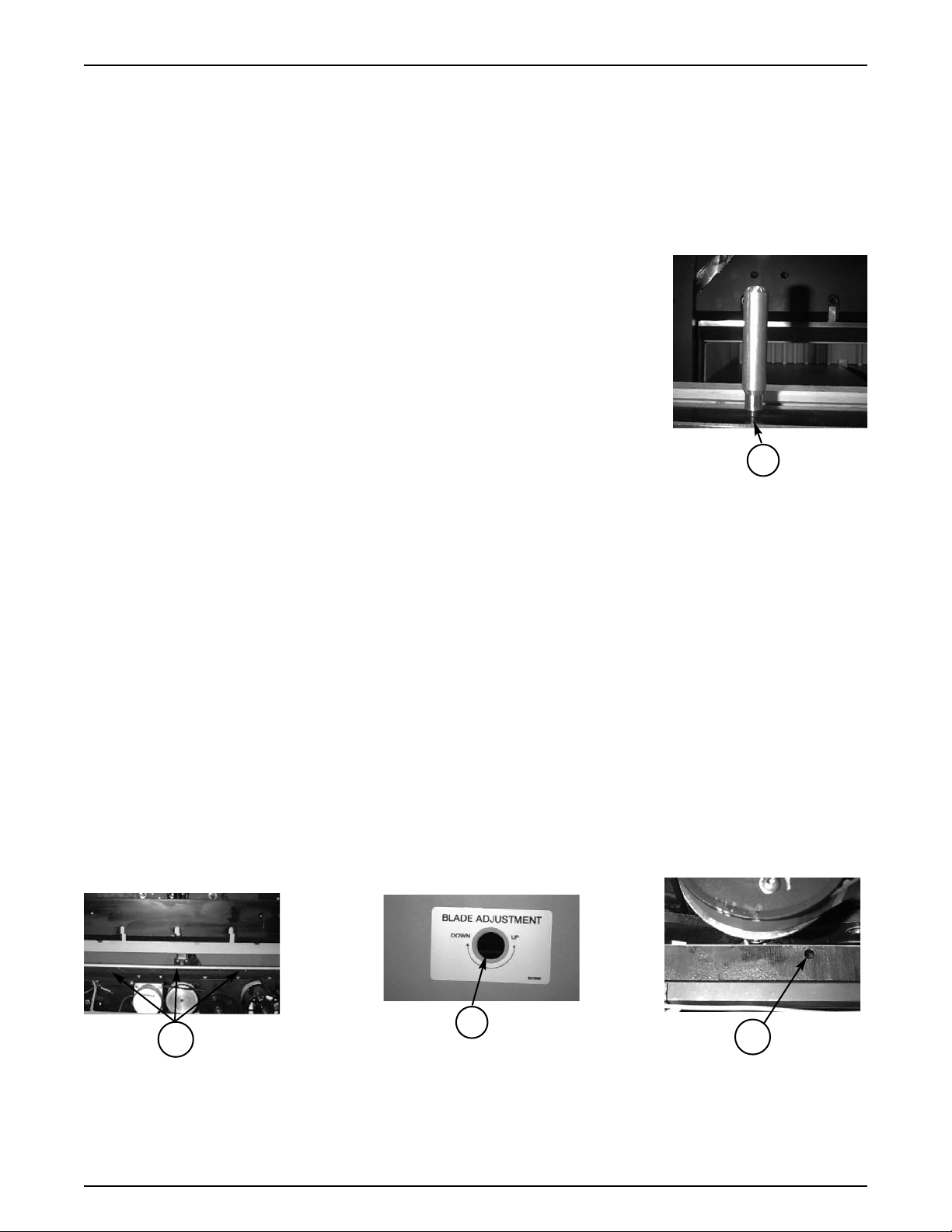
5. Move the blade to the right side and pull the left side of the blade toward the front of the machine. Now remove the
right side of the blade.
6. Secure the blade so the sharp edge will not be exposed and remove the blade holder tools.
7.2 Blade Installation
WARNING! The cutting blade is extremely sharp. Serious bodily harm can result from mishandling.
NOTE: To prevent dulling the knife, do not let the knife edge contact any surface except the cutting stick or blade
carrier. A newly sharpened or new blade will require adjustment for proper cutting.
See Section 7.3.
1. Raise the front safety cover. Turn the On/Off toggle switch and key switch off (key vertical).
NOTE: The front safety cover must be in the lowered position before the blade or
clamp will operate.
2. Install the blade holder in the two center blade mounting holes so that 1/4" to 5/16" (1)
of thread is visible between the blade and blade holder.
3. Lifting with the blade holders, place the blade into the blade carrier and securely tighten the blade holder tools.
4. Starting from the left end of the blade, insert and tighten two of the five blade screws.
Remove the blade holder tools and install and tighten the two blade retaining screws in their place. Lower the front safety
cover. To insert the far right blade screw, turn the On/Off toggle switch and key switch on. Lower the blade using the
blade switches, turn the On/Off toggle switch and key switch off (key vertical) when the blade reaches a position low
enough to access the remaining blade screw hole. Raise the front safety cover and insert and tighten the remaining screw.
5. Switch the On/Off toggle switch and key switch on so that the blade will travel to the up position.
7.3 Blade Adjustment
NOTE: When properly adjusted, the entire length of the blade should cut cleanly through the last sheet of the stack.
How deeply the blade indents the cutting stick depends on blade condition. Remember to adjust the blade position
only to the depth needed to cut cleanly through the last sheet of the stack.
WARNING! The blade must be adjusted so the cutting edge is above the bottom edge of the clamp when
both are in the full up position.
Due to normal blade wear, sharpening, or blade replacement it will be necessary to adjust the blade position. Blade adjustments control height and levelness.
There are three areas where the adjustments are made. 1) The blade screw holes in the blade carrier are slotted so the blade
can be move up/down in the carrier. 2) The blade height adjustment is accessible through the right side chassis panel. 3)
The leveling adjustment set screws located in the top of the blade carrier. The following procedure includes the removal of
the shroud and complete adjustment of the blade.
WARNING! The cutting blade is extremely sharp. Serious bodily harm can result from mishandling.
1. Disconnect power and remove the shroud.
A. Remove the two thumb knobs located on the left and right front surface of the shroud.
B. Remove the two screws at the bottom rear of the shroud.
PowerLine Operating Instructions
7
1
1
2
3
Page 8

C. On Model PL2100, remove the cap screw that secures the clamp handle to the shaft, and remove the handle.
D. Slide the shroud toward the front of the machine so the ready light is separated from the shroud. (On Model 2100, lift
the shroud until it clears the clamp shaft and then slide the shroud toward the front of the machine.
E. Lift the shroud from the electric cutter.
2. Make sure the blade is in the highest position (top of blade carrier slots). If necessary, install and tighten the blade holders. Loosen the blade retaining screws and move the blade to the top of the slot. (The blade must be lowered to access
the far right blade screw.) Retighten the blade retaining screws.
3. With the blade in the up position, measure the distance from the top of the blade carrier to the cutting stick. If necessary,
adjust the blade adjustment screw (accessible through the right side chassis panel) to a distance of 9 3/8".
4. Activate power, lower the blade to the lowest cutting position and turn off the On/Off toggle switch. Again measure from
the top of the blade carrier to the cutting stick. The distance should be 6 1/16". If necessary, raise the blade to its highest position and repeat step 4.
NOTE: The front safety cover must be in the lowered position before the blade or clamp will operate.
5. Place a 1/4" stack of paper over the cutting stick and initiate the cutting cycle. If the blade cuts evenly through the last
sheet of paper and just slightly into the cutting stick, no further adjustment is necessary. If the last sheet is not cut evenly through, proceed as follows:
A. Loosen the blade retaining screws so they hold the blade, but will allow movement when turning the blade leveling set
screws.
B. Adjust the blade leveling set screws clockwise in 1/4 turn increments and test cut until the bottom sheet of paper is
cleanly cut with the blade cutting slightly into the cutting stick. If the blade cannot be adjusted for a correct cut using
the blade leveling set screws, slide the blade to a lower position in the blade carrier slots and repeat the leveling adjustment. Raise the front safety cover.
6. After the blade has been adjusted for a correct cut, disconnect power and remove the front deck.
7. Inspect the trunnion gears on the blade adjustment shaft to ensure the gears are meshing in the center. If necessary,
adjust the shaft collars to obtain the proper gear mesh.
8. Reinstall the front deck and shroud.
9. Reinstall the thumb screws and rear deck screws to secure the shroud.
10.On Model PL2100, reinstall the clamp handle and secure with the cap screw.
NOTE: The bottom edge of the clamp should always be approximately 1/8" lower than the sharp edge of the blade.
7.4 Cutting Stick Rotation
The design of the PowerLine cutting stick allows rotation to eight cutting locations. (The stick may be rotated to four surfaces and reversed from end to end.) To rotate the stick proceed as follows:
1. Turn off power to the cutter. Turn the key switch to the off position (key vertical). Raise the front safety cover.
2. Carefully lift up one end of the cutting stick.
3. Place a flat tip screwdriver under the raised end of the cutting stick and slide it under
the length of the stick to completely remove it from the channel.
4. Rotate the stick to a new surface and place it back into the channel. When all four
surfaces have been used, reverse the stick end to end and repeat the rotation process
as needed. Replace the stick when a correctly adjusted new, or resharpened blade
will no longer cut through the bottom sheet of a stack.
7.5 Back Gauge Squaring Adjustment
If the cutting distance is not within 1/64" from one end of the back gauge to the other, proceed as follows:
1. Loosen the hex head bolt that secures the back gauge to the slider block (top rear center of the back gauge).
2. Loosen or tighten the socket head screws on the rear side of the back gauge as follows:
A. Cut paper at each end of the back gauge to determine which end needs to move closer to the cutting area. Slightly
loosen the socket head screw on the corresponding side. Slightly tighten the socket head screw on the opposite side.
B. Recheck the back gauge squareness by cutting paper positioned at each end of the back gauge.
C. Repeat the adjustment as necessary.
7.6 Back Gauge Slider Block Adjustment
1. Position the back gauge to approximately 20".
2. Turn off Power by turning the key switch to off (key vertical) and unplug the power cord from the power outlet.
PowerLine Operating Instructions
8
Page 9

3. Remove the lower rear cover. First move the screws/nuts joining the lower front and rear covers. Then remove the
phillips screws that secure the lower rear cover to the chassis. Allow the lower rear cover to drop until it clears the lower
front cover. Pull the lower rear cover forward and set it aside.
4. There are four screws that secure the nut plate assembly to the front of the slider block. The bottom 2 screws are socket
head (allen) cap screws, one of which also secures a lock washer. The top 2 are cross point screws. Loosen only the cap
screw with the lock washer.
5. The adjustment system is a push/pull arrangement that features Two hex socket screws extend approximately 1/4" from
the side of the block. (push). The other two screws extend through the block and are secured by two nuts. Slightly loosen
the front socket head cap screw that extends from the side of the slider block. Slightly tighten the other front socket head
cap screw that is threaded into the opposite side of the slider block. Tighten the screw until a slight resistance/bind is felt
when manually moving the back gauge. Next, slightly loosen the rear socket head cap screw that extends from the side
of the slider block. Slightly tighten the other rear socket head cap screw that is threaded into the opposite side of the
slider block to obtain smooth movement of the back gauge with no binding. Verify that the back gauge end play is minimal.
6. Retighten the cap screw on the slider block nut plate.
7. Slowly operate the back gauge the full length of travel. Verify that the back gauge does not bind or stall. Repeat the slider block adjustment if necessary.
8. Reinstall the lower rear cover.
9. Reapply power to the cutter.
7.7 Back Gauge Scale Calibration
If the actual cutting distance does not match the scale indicator, proceed as follows:
1. Position the back gauge and cut a minimum of three sheets of stock. Use the middle sheet as the reference for measurement.
2. Check the stock for a square cut. If the cut is not square to 1/64", perform the back gauge squaring procedure in Section
7.5. If the cut is square, proceed to the next step.
3. Turn off power to the cutter. Turn the key switch to the off position (key vertical). Unplug the power cord from the
power outlet.
4. Remove the bottom front and rear chassis covers.
5. Verify the tape cable is tight, no slack in the cable.
6. Loosen the cable locking screw on the side of the slider block. Hold the stand-off with pliers to prevent turning.
7. Move the cable until the correct tape reading is the same as the cut sheet. Tighten the cable locking screw on the side of
the slider block. Make sure the cable is in the groove on the end of the stand-off. Hold stand-off straight with pliers
while tightening.
8. Reinstall the bottom front and rear chassis covers.
9. Reapply power to the cutter.
7.8 Lubrication
The mechanical components of the cutter require periodic lubrication depending upon cutter use. A 30W oil, lithium base
grease, and 90W gear oil are the recommended lubricants. Heavy use is 8,000 or more cutting cycles per week. Moderate
use is 4,000 - 8,000 cutting cycles per week. This schedule is based on heavy use.
Part Frequency Lubricant
Tower Rails Every blade change/monthly grease
Clamp drive screw Every blade change/bi-monthly 30W oil
Clamp thrust bearing Annually grease
Clamp gear lever pivot pin Every blade change/monthly 30W oil
Clamp guides Every blade change grease
Crank gear/Gear box gear Bi-monthly grease
Gear box Annually 90W oil
Back gauge Acme screw Monthly 30W oil
All Oilite® bearings Annually 30W oil
Limit switch bracket pivot pts. Annually 30W oil
PowerLine Operating Instructions
9
Page 10

8.0 Troubleshooting
Following is a list of possible problems and their recommended solutions. If you encounter a problem not on the list or if
the recommended solution does not solve the problem, contact Martin Yale for technical assistance at (260) 563-0641.
PowerLine Operating Instructions
10
Solutions
Rotate the cutting stick. Check the blade adjustment. Make sure the blade cuts slightly into the cutting
stick. Sharpen or replace the blade. (See Sections 7.)
Check the blade adjustment. Make sure it is level and cuts slightly into the cutting stick. Check the cutting stick to make sure it is not bowed. (See Section 7.)
Make sure the power cord is plugged into a 20 Amp (NEMA #6-20R) receptacle. Check the 2A (F1) input
power fuse. Replace, if necessary. Check the key switch to make sure it is in the on position. (See Section 4.)
Reset the 12 Amp circuit breaker. Check to make sure the key switch is in the on position. Make sure
both blade switches are being pressed at the same time. Press the reset button and make sure the ready
light is on. Make sure the back gauge is not moving. (See Sections 2, 3, 4, 6.) Check to make sure the
front safety cover is in the lowered position.
Reset the 7 amp circuit breaker. Make sure the key switch is in the on position. Press the reset button
and make sure the key switch is in the on position. Make sure both clamp switches are being pressed at
the same time. Press the reset button and check that the ready light is on. Make sure the back gauge is
not moving. (See Sections 3 & 6.) Check to make sure the safety cover is in the lowered position.
Press the reset button. Check the operation of the blade limit switches. (See Section 2, 3, & 6.) Verify
that the key switch is on. Check the 2 Amp fuse. On Models PL2620, and PL2120: Check the operation of the clamp limit switch.
The blade is dull. Sharpen the blade. The dull blade may have caused the thermal protection of the blade
drive motor to stop the motor, Make sure the blade drive cooling fan is operating. (See Sections 6 & 7.)
Too much paper has been loaded which has disabled the upper clamp limit switch. (See Section 6.)
Make sure power is on. Check the 2 Amp fuse (F1). Replace, if necessary. Check the circuit breaker
and reset, if necessary. Check the light bulbs and replace, if necessary. (See Sections 2, 4, 6, & 7.)
Check for loose or damaged cable and cable connections. Ensure that the cable is tight. Check that all
cable pulleys rotate freely. Recalibrate tape position (Section 7.7).
Problem
1. The bottom sheet of a paper
stack is not cut.
2. The bottom sheets of paper
are only partially cut.
3. The electric cutter will not
power up.
4. The blade will not operate.
5. The clamp will not operate.
Models PL2620 & PL2120
ONLY
6. The ready light is not on.
7. The blade stalls.
8. The clamp will not raise
after the first cut. Models
PL2620 & PL2120 ONLY.
9. No cutting line.
10. Back gauge scale incorrect.
Page 11
Cutter Assembly
Item Part Number Qty. Description
1. M-O210084 1 Cutting Stick
(21" EC)
M-O260084 1 Cutting Stick
(26" EC)
2. W-O210160 1 Housing (21" EC)
W-O260160 1 Housing (26" EC)
3. W-O210086 1 Left Rear Deck (21" EC)
W-O260086 1 Left Rear Deck (26" EC)
4. W-O210101 1 Back gauge (21" EC)
W-O260101 1 Back gauge
(26" EC)
5. W-A210164 1 Rear Safety
Cover Assy
(21" EC)
W-A260164 1 Rear Safety Cover
Assy (26" EC)
6. W-O210087 1 Right Rear Deck
(21" EC)
W-O260087 1 Right Rear Deck
(26" EC)
7. M-S042004 1 Crank Wheel Knob
8. M-S037048 4 Leg Leveler
9. M-S006003 4 5/16-181 3/4"
Carriage Bolt
M-S007002 4 Acorn Nut
10. W-O210225 1 Front Deck (21" EC)
W-O260225 1 Front Deck (26" EC)
11. M-S005002 1 Back gauge Lock
Thumb Screw
14. W-O260246 1 Right End Cover
15. W-O260245 1 Left End Cover
16. M-O210247 1 Front Safety Cover Panel, 21”
M-O260247 1 Front Safety Cover Panel, 26”
Model PL2100
Parts same except for:
12. M-S037062 4 Vinyl Foam Grip
13. W-O260231 1 Clamp Handle Assy
Control Panels
Item Part Number Qty. Description
1. M-S033006 1 On/Off Toggle Switch, 220VAC
2. M-S033002 3 Momentary Pushbutton Switch
3. M-S033022 1 Momentary Pushbutton Switch
4. M-O260090 1 Left Control Panel Housing
5. M-O260091 1 Right Control Panel Housing
6. W-A260184 1 Keylock Switch
Model PL2100
Parts same except for:
2. M-S033002 2 Momentary Pushbutton Switch
PowerLine Operating Instructions
11
21
43
14
9
10
7
11
16
1
15
2
3
4
5
6
8
13
12
Page 12
PowerLine Operating Instructions
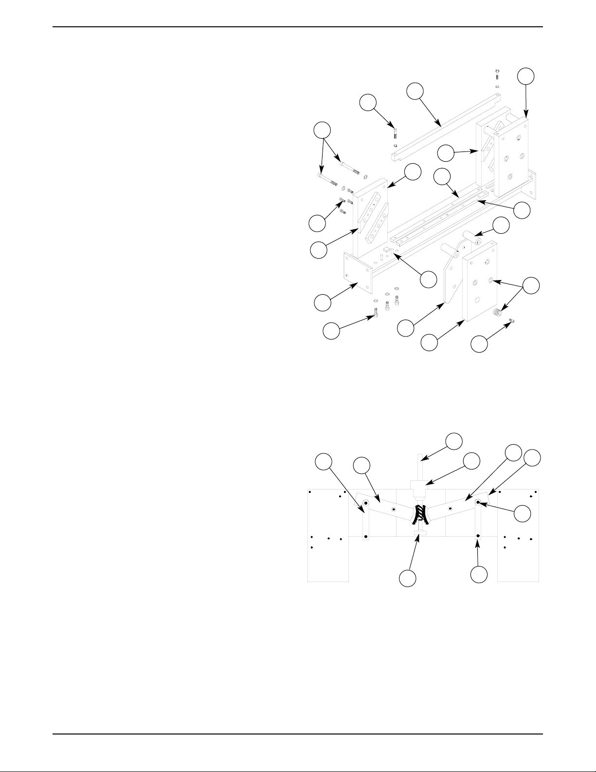
T-Frame Assembly
Item Part Number Qty. Description
1. M-S006011 4 3/8” - 16x3 1/2” Bolt
2. M-S003034 2 1/4"-20x1 1/4" Hex Hd Bolt
M-S008010 2 1/4"ID Split Lock Washer
3. W-O210014 1 Tower Tie Bar (21")
W-O260014 1 Tower Tie Bar (26")
4. W-A260022 1 Right Rear Tower Ass’y
5. W-A260020 1 Right Front Tower
6. W-I210092 1 Rear Deck Spacer (21")
W-I260092 1 Rear Deck Spacer (26")
7. W-I210093 1 Front Deck Spacer (21")
W-I260093 1 Front Deck Spacer (26")
8. W-O260043 4 1” OD x 1.937” Spacer
9. W-O260257 8 Gib Adjuster
10. W-O260019 1 Left Front Tower
11. W-G260256 2 Gib Plate
12. M-S018031 8 1/4"x1" Dowel Pin
13. M-S006009 12 3/8"-16x1" Hex Hd Bolt
M-S008003 16 3/8" USS Split Lock Washer
14. W-W210015 1 T-Frame Base (21")
W-W260015 1 T-Frame base (26")
15. W-O260258 4 Tower Rail
16. M-S003015 16 5/16-18 x 3/4 Socket H.D. Screw
17. W-A260021 1 Left Rear Tower Ass’y
Clamp Drive, Front View
Item Part Number Qty. Description
1. W-O260050 1 Clamp Lever Link Arm
2. W-A260175 1 Left Clamp Lever Assy
3. W-O260057 1 Clamp Drive Shaft
4. ——- 1 Upper Bearing Mount
M-S020001 1 30mm Ball Thrust Bearing
M-S048010 1 Grease Fitting
M-S010002 2 5100-37 Retaining Ring
M-S011001 1 3/16"x1 1/2" Key
M-S010035 1 Internal Retaining Ring
M-S001084 1 4-40x5/16 Phil Pan Head Screw
W-O260056 1 Thrust Washer
5. W-A260058 1 Lower Bearing Assy
M-S013021 1 Oilite Bearing
W-O260058 1 Lower Bearing Mount
6. W-O260173 1 Clamp Sensor Bracket
M-S045170 1 Clamp Sensor
7. W-A260255 1 Right Clamp Lever Ass’y
8. W-O260254 1 Right Link Arm
9. W-O260253 1 Eccentric Bushing
Not Illustrated
W-O260066 2 Clamp Lever Bushing
Model PL2100
Parts the same except for:
3. W-O210224 1 Clamp Drive Shaft
12
1
2
16
9
8
7
17
6
5
4
3
10
11
15
13
14
16
12
9
8
5
6
4
3
2
1
7
Not Illustrated
W-O260066 2 Clamp Lever Bushing
Page 13
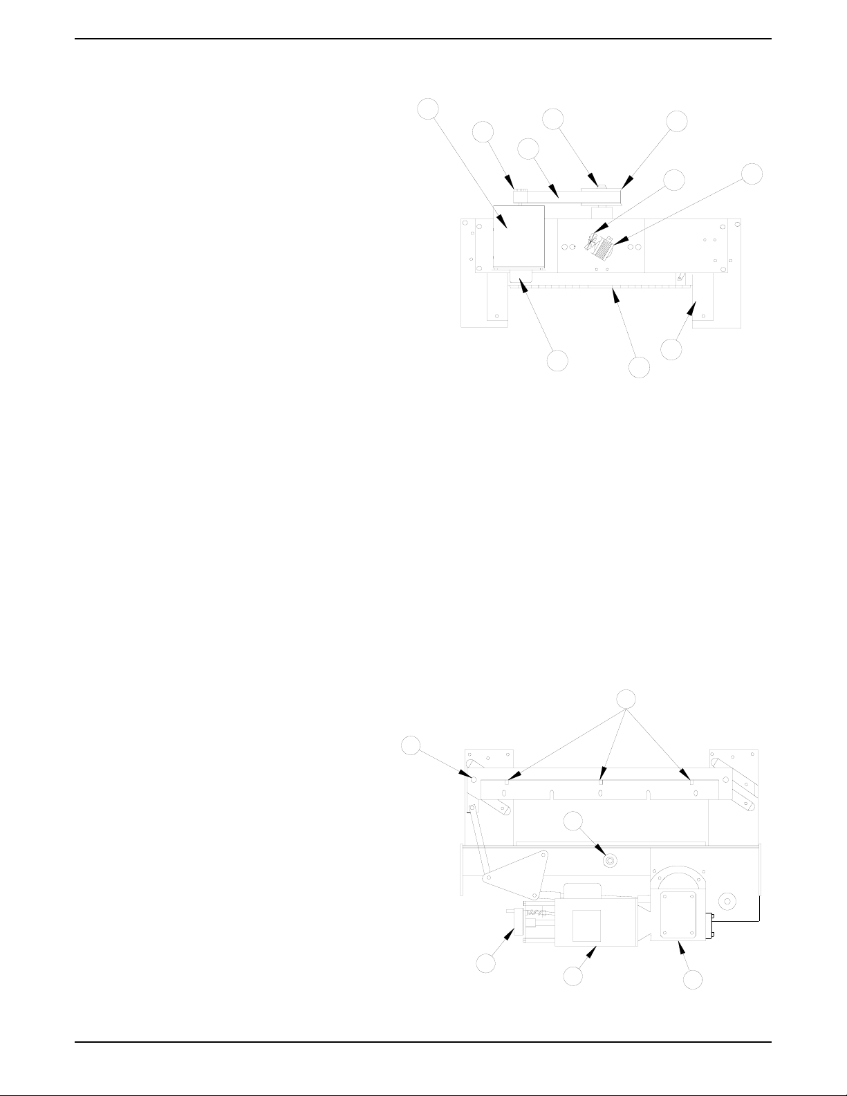
Clamp Drive, Rear View
Item Part Number Qty. Description
1. M-S021009 1 Clamp Drive Motor
2. W-O260077 1 12L Clamp Motor Pulley
3. M-S025003 1 300XL100 Timing Belt
4. W-O260076 1 Drive Screw Collar
M-S002007 2 10-32x3/16 Set Screw
5. W-A260071 1 Clamp Pulley Assy
M-S003004 2 1/4"-20x1/2" Hex Hd Screw
M-S008029 2 1/4"ID Internal Lock
Washer
M-S63751051 2 1/4"-20x1/2" Button
Hd Screw
W-N260071 1 36L Pulley
W-O260068 1 Lower Pulley Hub Assy
W-O260072 1 36L Innter Pulley Hub
W-O260074 1 Upper Pulley Flange
W-O260075 2 Bumper
6. M-S037061 1 Fan Blade
7. M-S021014 1 Cooling Fan Motor, 230VAC
8. W-A210061 1 Clamp Assy (21" EC)
W-A260061 1 Clamp Assy (26" EC)
9. M-S045130 1 220V, 15lb Brake
10. W-O260060 2 Clamp Guide
Model PL2100
8. W-A210061 1 Clamp Assy (21" EC)
10. W-O260060 2 Clamp Guide
Blade Drive Assembly,
Rear View
Item Part Number Qty. Description
1. M-S002058 3 1/4"-20x1 1/2"
Set Screw
2. M-O260132 1 Gear Box, 40:1
3. M-S021010 1 Blade Drive Motor,
220VAC
4. M-S045130 1 220V, 15LB. Brake
5. W-O260113 1 Bearing Hub
M-S020002 1 Bearing
6. W-O260024 4 Blade Carrier Roller
Not Illustrated
M-S022084 1 18T, 8P Steel Spur Gear
W-A260170 2 Knife Holder Tool
PowerLine Operating Instructions
13
9
8
10
7
6
5
4
3
2
1
1
6
4
3
2
5
Not Illustrated
M-O210062 1 False Clamp Plate (21" EC)
M-O260062 1 False Clamp Plate (26" EC)
M-S63751592 3 10-32x3/8 Flat Hd Socket
Screw (21" EC)
4 10-32x3/8 Flat Hd Socket
Screw (26" EC)
W-O260051 1 Clamp Switch Brkt
W-O260052 1 Clamp Limit Switch Lever
M-S031017 1 Extension Spring, Clamp Limit
M-S033009 1 Microswitch, Clamp Limit
W-O260252 1 Clamp Fan Motor Bracket
Page 14
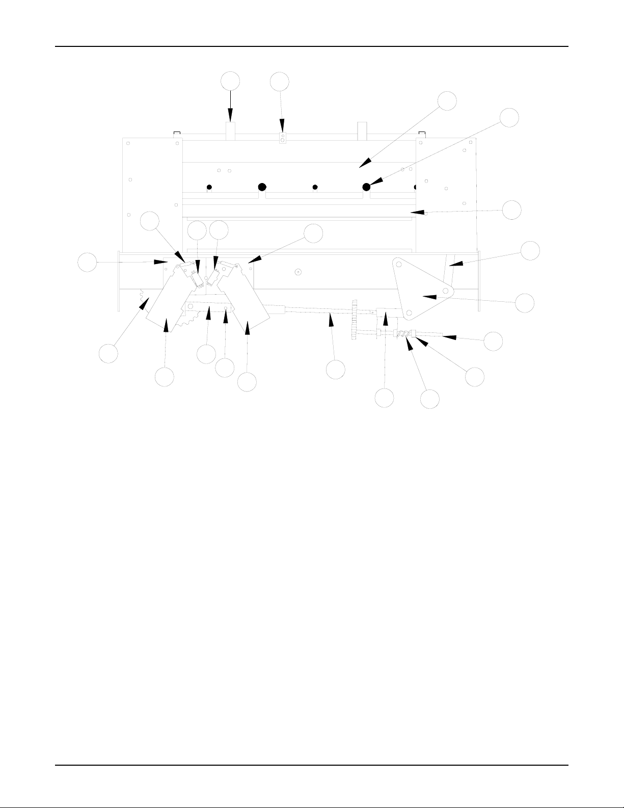
Blade Drive Assembly,
Front View
Item Part Number Qty. Description
1. W-O260185 2 Cut Line Lamp Bracket
M-S045146 2 Lamp Socket
M-S045148 2 1141 Lamp
2. W-O260154 1 Ready Light Bracket
M-S045141 1 Ready Light, Amber
3. W-A210029 1 Blade Carrier Assy (21" EC)
W-A260029 1 Blade Carrier Assy (26" EC)
4. M-S003006 5 7/16"-14x5/8" Socket
Head Cap Screw
5. M-O210031 1 Knife (21" EC)
M-O260031 1 Knife (26" EC)
6. W-A260032 2 Carrier Link Assy
7. W-A260030 2 Bell Lever Assy
8. W-A260042 1 Trunnion Adjustment Shaft
9. M-O820584 3 1/2"ID Shaft Collar
10. M-S031015 1 Compression Spring
12. W-O260040 1 Push Pull Shaft Assy
14. W-O260127 1 LH Limit Switch Brkt
15. W-O260126 1 RH Limit Switch Brkt
16. W-O260129 1 Lever, Right
Item Part Number Qty. Description
17. W-A260038 1 Long Trunnion Assy
18. W-O260123 1 Lever, Left (Rear)
W-O260138 Blade Safety Switch (Front)
19. W-A260036 1 Crank Gear Assy
20. M-S033012 2 Microswitch, Single Pole
21. M-S031013 3 Extension Spring
22. M-S033011 1 Microswitch, Double Pole
Staggered
29. W-A260039 1 Short Trunnion Assy
30. W-O260139 1 Blade Safety Switch Cam
Not Illustrated
M-S021014 1 Cooling Fan Motor, 230VAC
M-S037061 1 Fan Blade
W-A260170 2 Blade Handle
PowerLine Operating Instructions
14
19
18
17
30
16
12
29
10
9
8
7
6
5
4
3
2
1
14
21
15
22
20
Page 15
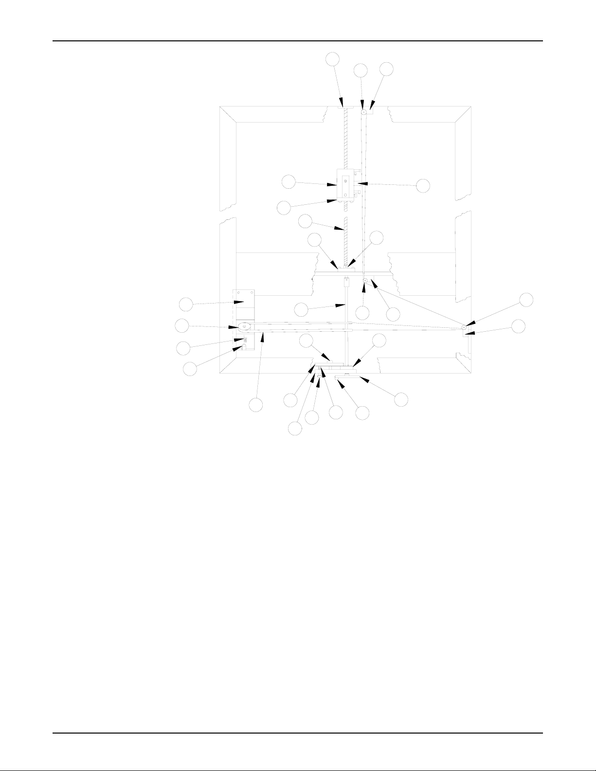
Item Part Number Qty. Description
1. W-O260216 1 Tape Pulley Bracket Assy
2. W-O260217 1 Tape Pulley
3. W-O260219 1 Tape Indicator
4. M-S045148 1 Tape Indicator Lamp, 1141
M-S045146 1 Lamp Socket
5. W-A210220 1 Tape Assy (21" EC)
W-A260220 1 Tape Assy (26" EC)
6. W-O260228 1 Crank Brake Pad
7. W-A260227 1 Crank Brake Plate Assy
M-S013052 1 Flanged Bearing
8. W-O260226 1 Crank Brake Disc
9. M-S005002 1 Thumb Screw, 5/16-18
10. M-S031020 1 Compression Spring
11. M-S032014 1 Crank Knob
M-S006027 1 Shoulder Screw
12. W-O260211 1 Crank Wheel
13. M-O820711 1 1/4-20x1 1/4 Bolt
14. W-O260223 3 Cable Pulley Bracket
15. W-O260222 5 Cable Pulley
17. W-O260212 1 Extension Shaft Assy
18. W-O260113 1 Bearing Hub
M-S020002 1 Ball Bearing
M-S010036 1 Retaining Ring
19. M-S019029 1 12mm Shaft Collar
Item Part Number Qty. Description
20. W-O260112 1 5/8-4,2ST Acme Shaft
21. W-A260210 1 Nut Plate Assy, Manual B/G
M-S007028 1 5/8-4,2ST Acme Nut
22. W-O260104 1 Slider Block
M-S013019 2 Slider Block Bushing (Split)
M-S003032 2 10-32x1 1/4" Cap Screw
M-S003084 2 10-32x1 3/4" Cap Screw
M-S007008 2 10-32 Keps Nut
23. W-O260124 1 Spacer
M-S008005 1 #10 Flat Washer
M-S008004 1 #10 Lock Washer
M-S003032 1 10-32x1 1/4" Cap Crew
24. M-O260120 1 Shock Mount Bushing
Not Illustrated
W-O210100 1 Back Gauge Guide Shaft
(21" EC)
W-O260100 1 Back Gauge Guide Shaft
(26" EC)
W-O260106 1 Front Mounting Block
(Guide Shaft)
PowerLine Operating Instructions
15
7
5
4
3
2
1
17
6
9
10
11
12
14
15
14
15
22
21
20
18
19
23
24
15
14
13
8
Back Gauge Drive
Assembly, Top View
Page 16
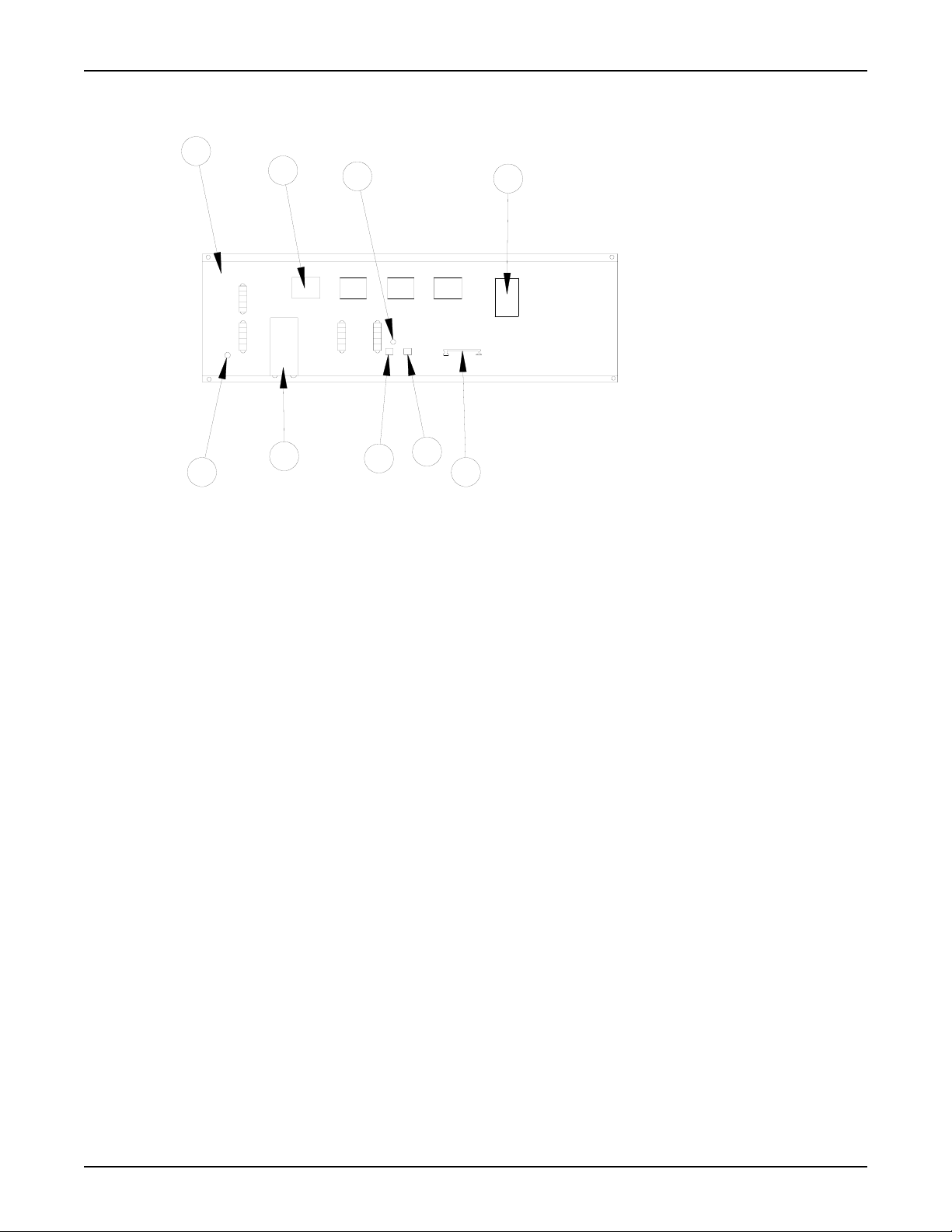
Electric Component Panel
Item Part Number Qty. Description
1. M-O210096 1 Electrical Component Panel (21" EC)
M-O260096 1 Electrical Component Panel (26" EC)
2. M-S045144 4 Contactor
M-S045145 5 Auxiliary Contactor
3. M-S045098 1 2 Amp Slow Blow Fuse, (F1), Main
M-S045065 1 Fuse Holder
5. W-A260144 1 220V Transformer Assy, Control
7. M-S033039 4 5 Position Terminal Block
9. M-O260142 1 Relay Board
12. M-S045142 1 12 Amp Circuit Breaker
13. M-O850421 1 25mfd 440V Capacitor, clamp
14. M-S045050 1 DC Rectifier
15. M-S045143 1 7 Amp Circuit Breaker
Model PL2100
Parts same except for:
2. M-S045144 2 Contactor
M-S045145 2 Auxiliary Contactor
12. Not used for this model.
13. Not used for this model.
PowerLine Operating Instructions
16
1
2
3
5
9
15
12
13
14
Page 17
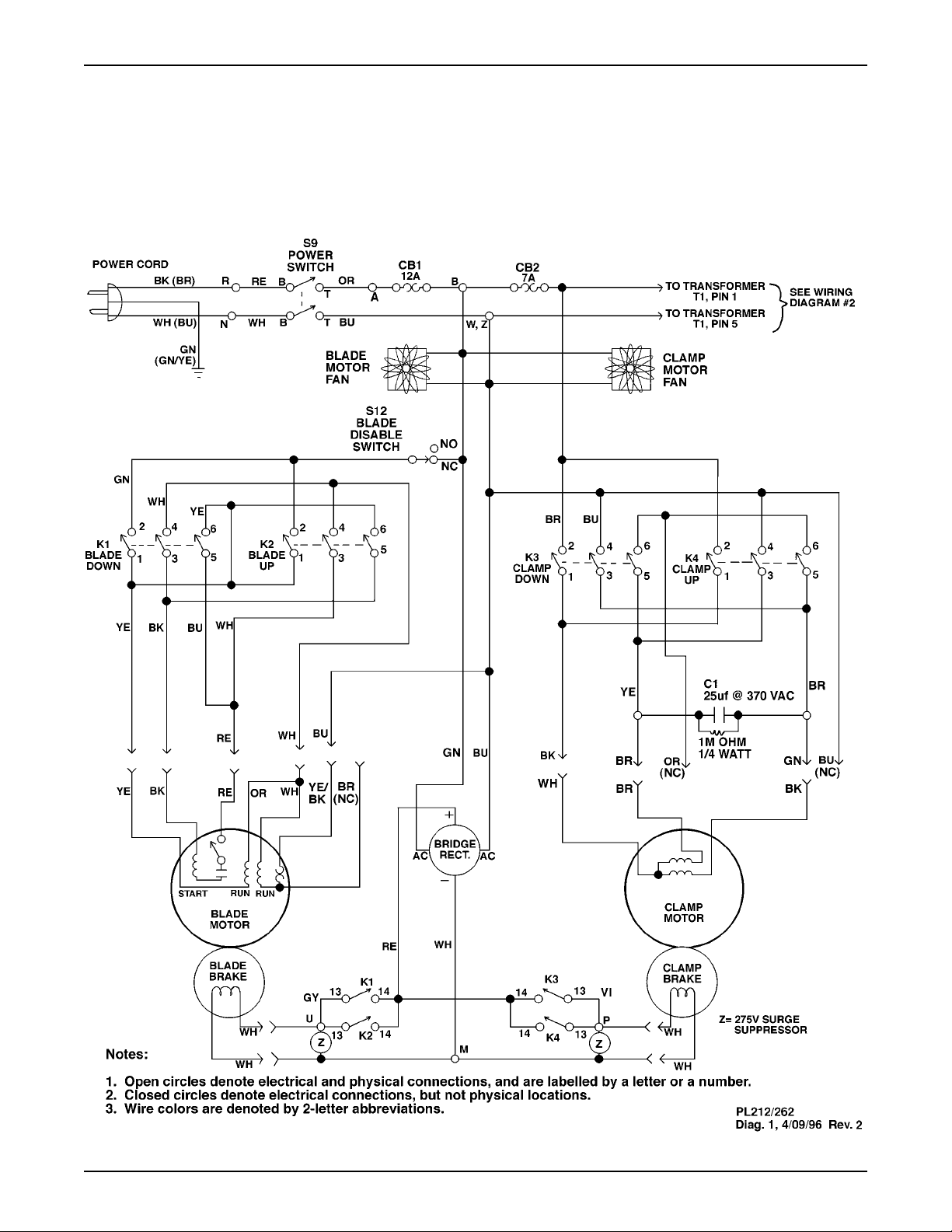
PowerLine Operating Instructions
17
Wiring Diagram 1, Clamp and Blade Motor Section
Models PL2620 and PL2120
Page 18
PowerLine Operating Instructions
18
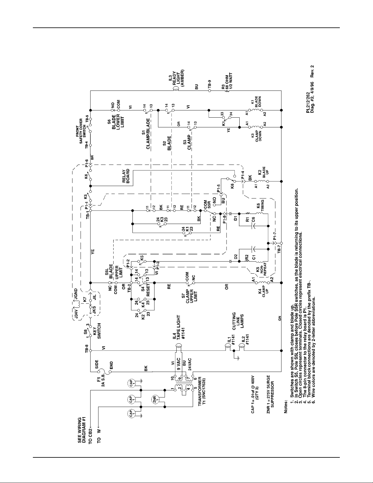
Wiring Diagram 2, Clamp and Blade Controls Section
Models PL2620 and PL2120
Page 19
PowerLine Operating Instructions
19
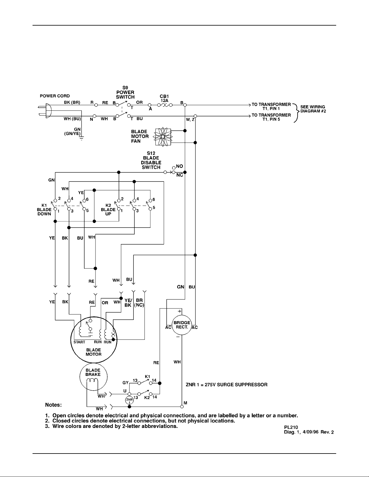
Wiring Diagram 1, Blade Motor Section
Model PL2100
Page 20
PowerLine Operating Instructions
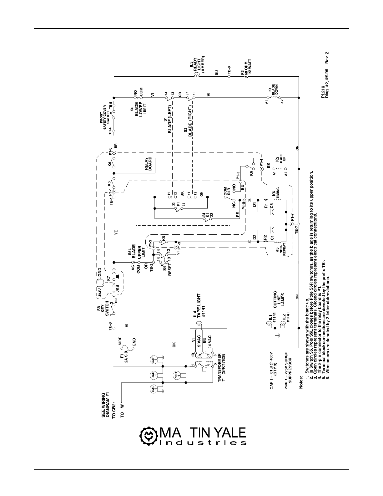
Wiring Diagram 2, Blade Controls Section
Models PL2100
251 Wedcor Ave. Wabash, IN 46992
Phone (260) 563-0641 Fax (260) 563-4575
Website: www.martinyale.com Email: [email protected]
M-S027113 Rev. 1 12/13/06
R
 Loading...