

PowerLift SBL460 Owner's Manual
by
Body-Solid
®
Freeweight Leverage Gym System
OWNER’S MANUAL
&
Mainframe Assembly Instructions
SBL460
Mainframe
Table of Contents
Reference Drawings . . . . . . . . . . . . . . p. 1-2
Safety Instructions . . . . . . . . . . . . . . . . . p. 3
Room Layout Diagrams . . . . . . . . . . . . . p. 4
Preparations . . . . . . . . . . . . . . . . . . . . . . p. 5
Assembly Instructions . . . . . . . . . . . . p .6-25
Safety Guidelines . . . . . . . . . . . . . . . . . p. 26
Warning, Safety & Maintenance . . . p. 27-29
Counter-Balance Warning . . . . . . . . . . . p. 28
Notes . . . . . . . . . . . . . . . . . . . . . . . . . . .p. 30
Phrases, Terms, Tips & Guidelines . .p. 31-32
Nutrition . . . . . . . . . . . . . . . . . . . . . . . . .p. 33
Exercise Prescription . . . . . . . . . . . . . . .p. 34
Training Tips . . . . . . . . . . . . . . . . . . . . .p. 35
Common Training Mistakes . . . . . . . . . .p. 36
Setting Up Your Personal Program . . . . .p.37
Determine Your Training Method . . . . . .p. 38
Exercise Tips . . . . . . . . . . . . . . . . . . . . .p. 39
Anatomy Chart . . . . . . . . . . . . . . . . . . . .p. 40
Fitness Goals . . . . . . . . . . . . . . . . . . . . .p. 41
Exercise Logs . . . . . . . . . . . . . . . . . .p. 42-44
Stretching & Flexibility . . . . . . . . . . . . .p. 45
Stretching: Warm-Up / Cool-Down . .p. 46-55
Build The Ultimate Fitness Center . . . . .p. 56
Mainframe Parts List . . . . . . . . . . . . . . p. 57
Hardware Parts List . . . . . . . . . . . . . p. 58-59
Pads List, Cables List &
Accessories List . . . . . . . . . . . . . . . . . . p. 60
Hardware Diagrams . . . . . . . . . . . . . p. 61-63
Exploded View Diagram . . . . . . . . . . p. 64-65
1
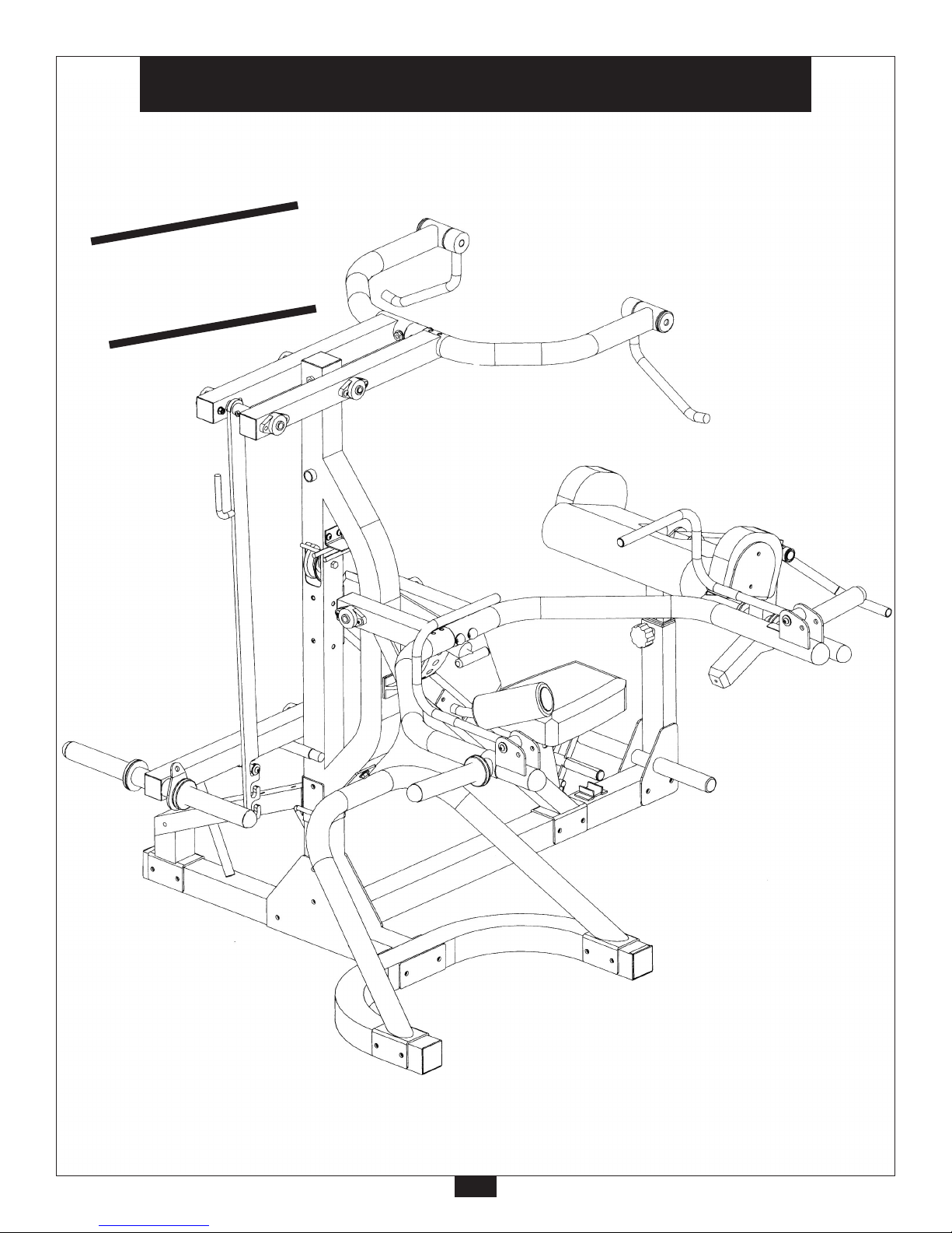
PowerLIFT Mainframe SBL460
Reference Drawings
PATENT
PENDING
2
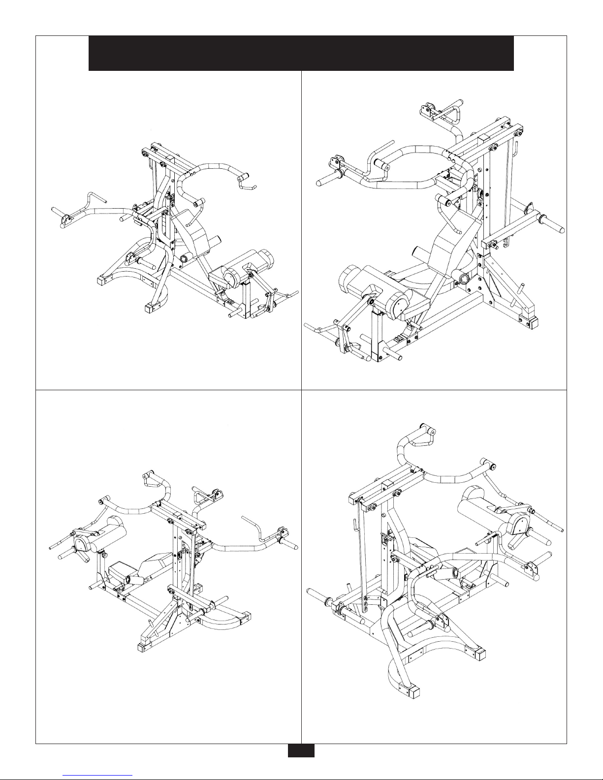
PowerLIFT Mainframe SBL460
Reference Drawings
Note: Due to continuing product improvements, specifications and designs are subject to
change without notice.
Even though we have prepared this manual with extreme care, neither the publisher nor the
author can accept responsibility for any errors in, or omission from, the information given.

Important Safety Instructions
Before beginning any fitness program, you should obtain a complete physical examination from your physician.
Il est conseille de subir un examen medical complet avant d’entreprendre tout programme d’exercise.
Si vous avez des etourdissements ou des faiblesses, arretez les exercices immediatement.
Antes de comenzar cualquier programma de ejercicios, deberias tener un examen fisico con su doctor.
•
•
•
•
•
•
•
•
•
•
•
•
•
•
•
•
When using exercise equipment, you
should always take basic precautions,
including the following:
Read all instructions before using the PowerLIFT
Gym. These instructions are written to ensure your
safety and to protect the unit.
Do not allow children on or near the equipment.
Use the equipment only for its intended purpose as
described in this guide. Do not use accessory
attachments that are not recommended by the
manufacturer. Such attachments might cause injuries.
Wear proper exercise clothing and shoes for your
workout—no loose clothing.
Use care when getting on or off the unit.
Do not overexert yourself or work to exhaustion.
If you feel any pain or abnormal symptoms, stop your
workout immediately and consult your physician.
Never operate unit when it has been dropped or
damaged. Return the equipment to a service center
for examination and repair.
Never drop or insert objects into any opening in the
equipment.
Always check the unit and its cables before each
use. Make sure that all fasteners and cables are
secure and in good working condition.
Do not use the equipment outdoors or near water.
Always use collars on weight plate posts.
Personal Safety During Assembly
It is strongly recommended that a qualified dealer
assemble the equipment.
Assistance is required.
Before beginning assembly, please take the time to
read the instructions thoroughly.
Read each step in the assembly instructions and
follow the steps in sequence. Do not skip ahead. If
you skip ahead, you may learn later that you have to
disassemble components and that you may have
damaged the equipment.
Assemble and operate the PowerLIFT Gym on a
solid, level surface. Locate the unit a few feet from
the walls or furniture to provide easy access.
The PowerLIFT Gym is designed for your enjoyment.
By following these precautions and using common
sense, you will have many safe and pleasurable hours
of healthful exercise with your Body-Solid PowerLIFT Gym.
After assembly, you should check all functions to
ensure correct operation. If you experience problems,
first recheck the assembly instructions to locate any
possible errors made during assembly. If you are unable
to correct the problem, call the dealer from whom
you purchased the machine or call 1-800-556-3113
for the dealer nearest you.
Obtaining Service
Please use this Owner’s Manual to make sure that all
parts have been included in your shipment. When
ordering parts, you must use the part number and
description from this Owner’s Manual. Use only
Body-Solid replacement parts when servicing this
machine. Failure to do so will void your warranty and
could result in personal injury.
For information about product operation or service,
check out the official Body-Solid website at
www.bodysolid.com or contact an authorized
Body-Solid dealer or a Body-Solid factory-authorized
service company or contact Body-Solid customer
service at one of the following:
Toll Free: 1-800-556-3113
Phone: 1-708-427-3555 ext. 5
Fax: 1-708-427-3598
E-mail: service@bodysolid.com
Or write to: Body-Solid, Inc.
Service Department
1900 S. Des Plaines Ave.
Forest Park, IL 60130 USA
Retain this Owner’s Manual for future
reference. Part numbers are required
when ordering parts.
3
Before You Begin
Thank you for purchasing the PowerLIFT Gym. This gym is part of the Body-Solid line of quality strength
training machines, which let you target specific muscle groups to achieve better muscle tone and overall
body conditioning. To maximize your use of the equipment please study this Owner’s Manual thoroughly.
•
Unpacking the Equipment
The PowerLIFT Gym is carefully tested and inspected
before shipment. Body-Solid ships the unit in several
pieces that require assembly. Ask for assistance
during the assembly process.
Carefully unpack the boxes and lay the pieces on
the floor near the place where you plan to use the
equipment.
Be careful to assemble all components in the
sequence presented in this guide.
If any items are missing, contact the dealer from whom
you purchased the unit or call 1-800-556-3113 for
the dealer nearest you.
OPTIONAL Equipment
Optional equipment that you can purchase through
your dealer include the FID46 PowerLIFT Flat / Incline
/ Decline Bench, LSA50 PowerLIFT Squat / Calf
Station, and the WT46 PowerLIFT Six-post Olympic
Weight Tree.
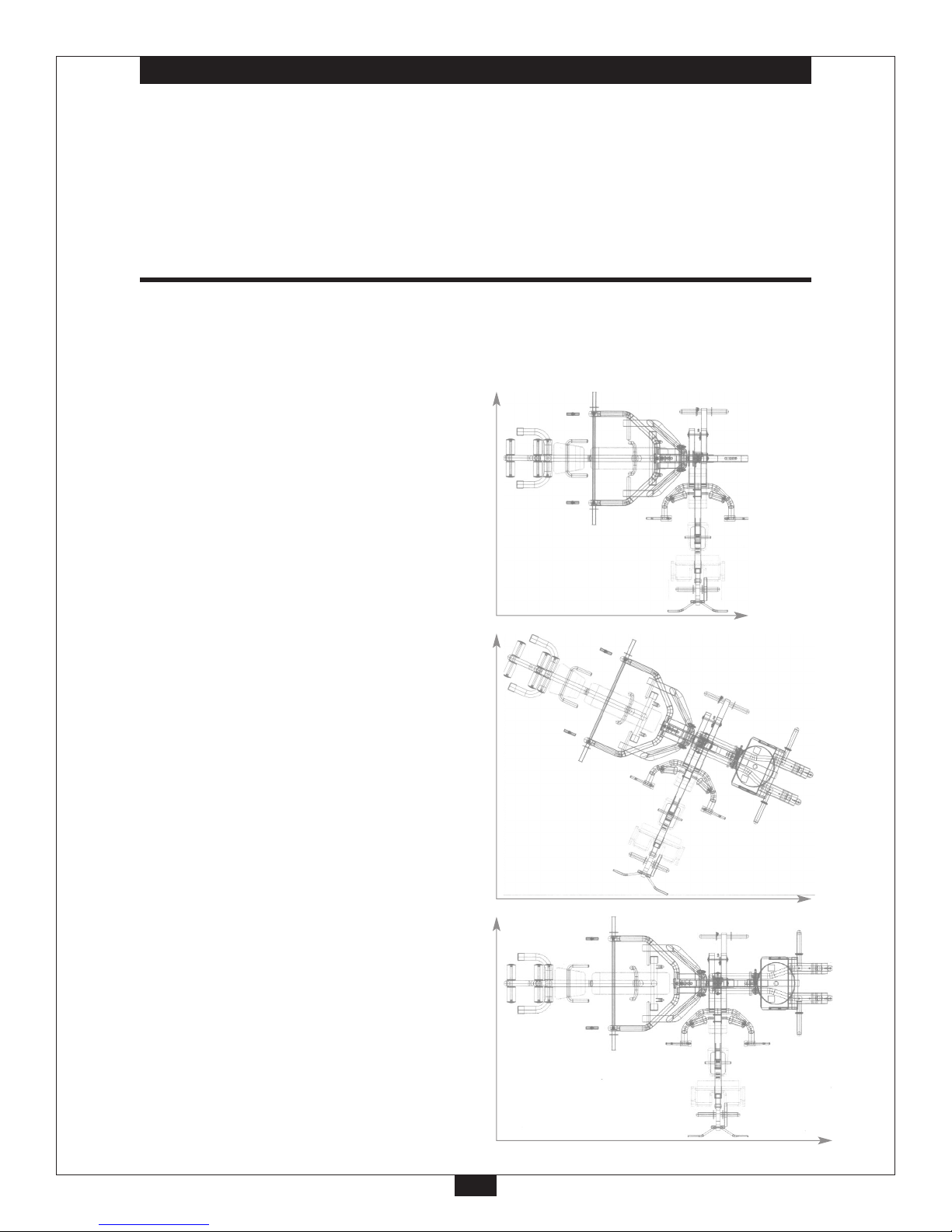
10'
10'
10'
12'
10'
13'
These room layout diagrams will help you decide the best
placement for your PowerLIFT Gym (with or without the
LSA50 Squat / Calf Station).
Without LSA50 PowerLIFT
Squat / Calf Station
With LSA50 PowerLIFT
Squat / Calf Station
With LSA50 PowerLIFT
Squat / Calf Station
4

Preparations
CAUTION: To set up this unit, you will need assistance. Do not attempt assembly by yourself.
You must review and follow the instructions in this Owner’s Manual. If you do not assemble and use the
PowerLIFT Gym according to these guidelines, you could void the Body-Solid warranty.
•
•
•
•
•
Required Tools
The tools that you must obtain before assembling
the PowerLIFT Gym include:
2.5mm Hex Key
5mm Hex Key
6mm Hex Key (You need two)
8mm Open-End Wrench
10mm Open-End Wrench
14mm Open-End Wrench
17mm Open-End Wrench
19mm Open-End Wrench
17mm Box Wrench
19mm Box Wrench
Rubber Mallet
Installation Requirements
Follow these installation requirements when assembling
the PowerLIFT Gym:
Fill out and mail warranty card.
Set up the PowerLIFT Gym on a solid, flat surface.
A smooth, flat surface under the machine helps keep
it level. A level machine has fewer malfunctions.
Provide ample space around the machine. Open
space around the machine allows for easier access.
Insert all bolts in the same direction. For aesthetic
purposes, insert all bolts in the same direction
unless specified (in text or illustrations) to do otherwise.
Leave room for adjustments. Tighten fasteners such as
bolts, nuts, and screws so the unit is stable, but leave
room for adjustments. Do not fully tighten fasteners
until instructed in the assembly steps to do so.
5
CAUTION: Obtain assistance! Do not attempt to
assemble the PowerLIFT Gym by yourself. Review the
Installation Requirements before proceeding with the
following steps.
The PowerLIFT Gym mainframe unit comes in four
boxes. Be careful to assemble components in the
sequence presented in this guide.
NOTE: With so many assembled parts, proper alignment
and adjustment is critical. While tightening the nuts
and bolts, be sure to leave room for adjustments.

•
•
•
Assembly Instructions
Assembly of the PowerLIFT Gym takes professional installers about 2.5 hours to complete. If this is the first
time you have assembled this type of equipment, plan on significantly more time.
Professional installers are highly recommended!
However, if you acquire the appropriate tools, obtain assistance, and follow the assembly steps sequentially,
the process will take time, but is fairly easy.
IMPORTANT!
Before you begin you should fold-out pages 61, 62 and 63.
This is a quick reference guide that shows all hardware
parts (in actual size) along with the corresponding key
numbers on the assembly instructions.
6
Assembly Tips
Read all “Notes” on each page before beginning each step.
While you may be able to assemble the PowerLIFT Gym
using the illustrations only, important safety notes and other
tips are included in the text.
Some pieces may have extra holes that you will not use. Use
onlythose holes indicated in the instructions and illustrations.
NOTE: To find out the length of a particular bolt, measure its
shank (the long, narrow part beneath the head). Refer to the
following diagram:
Do not fully tighten bolts until instructed to do so.
Note: After assembly, you should check all functions
to ensure correct operation. If you experience
problems, first recheck the assembly instructions
to locate any possible errors made during assembly.
If you are unable to correct the problem, call the
dealer from whom you purchased the machine or
call 1-800-556-3113 for the dealer nearest you.
mm
Inch

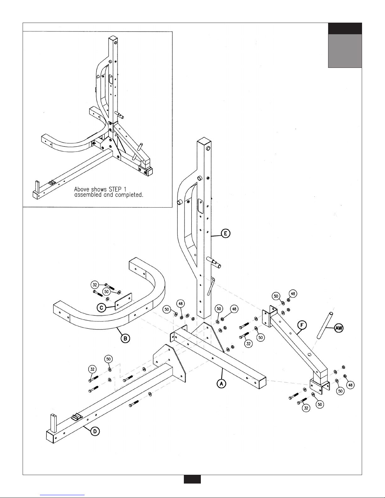
STEP
1
Be careful to assemble all components
in the sequence they are presented.
IMPORTANT! Before you begin you should
fold-out pages 61, 62 and 63.
This is a quick reference guide that shows all hardware parts (in actual size)
along with the corresponding key numbers on the assembly instructions.
Note:
Finger tighten all hardware in this step. Do not wrench tighten until the end of Step 2.
A. Open hardware package labeled “Step 1”.
B. Attach main base frame (A) to U base frame (B) using brace plate (C) and the following hardware.
two 32 (hex bolt 12mm x 105mm partial thread)
four 50 (flat washer 12mm)
two 48 (nylon lock nut 12mm)
C. Obtain assistance for this step.
Have assistant hold vertical mainframe (E) in place on top of main base frame (A).
Connect lat base frame (D) to vertical mainframe (E) and main base frame (A) as shown using:
four 32 (hex bolt 12mm x 105mm partial thread)
eight 50 (flat washer 12mm)
four 48 (nylon lock nut 12mm)
D. Attach squat support frame (F) to vertical mainframe (E) and main base frame (A) using:
four 32 (hex bolt 12mm x 105mm partial thread)
eight 50 (flat washer 12mm)
four 48 (nylon lock nut 12mm)
E. Slide counter-balance weight post (AW) into squat support frame (F) as shown.
7
mm
Inch
STEP
1
8

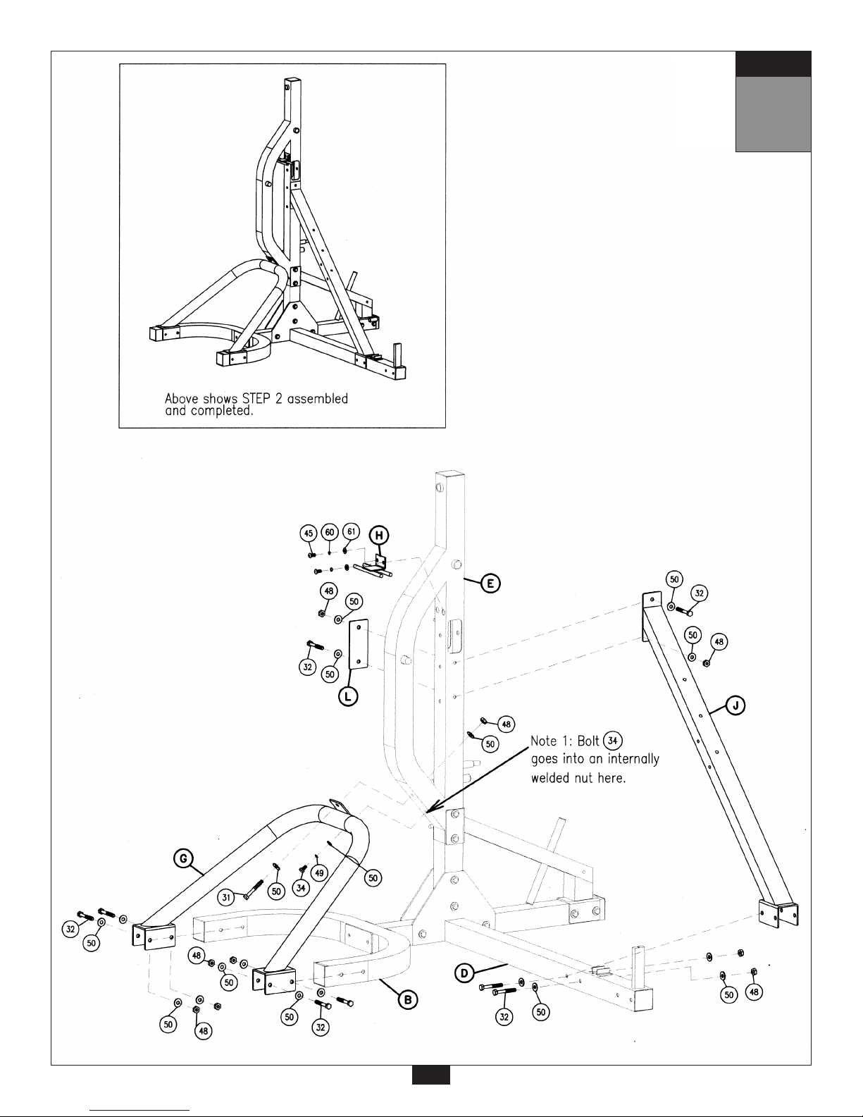
STEP
2
Be careful to assemble all components
in the sequence they are presented.
A. Open hardware package labeled “Step 2”.
B. Attach press support frame (G) to U base frame (B) and vertical mainframe (E) as shown using:
four 32 (hex bolt 12mm x 105mm partial thread)
eight 50 (flat washer 12mm)
four 48 (nylon lock nut 12mm)
one 31 (hex bolt 12mm x 100mm partial thread)
three 50 (flat washer 12mm)
one 48 (nylon lock nut 12mm)
one 34 See Note 1. (hex bolt 12mm x 25mm full thread)
one 49 (spring lock washer 12mm)
C. Attach accessory holder (H) to vertical mainframe (E) as shown using:
two 45 (round allen head 8mm x 20mm full thread bolt)
two 60 (spring lock washer 8mm)
two 61 (flat washer 8mm)
D. Attach lat support frame (J) to lat base frame (D) and vertical mainframe (E) using brace plate (L)
and the following hardware:
four 32 (hex bolt 12mm x 105mm partial thread)
eight 50 (flat washer 12mm)
four 48 (nylon lock nut 12mm)
Note: At this point you must make sure that the gym is level, stable and in the right location.
You should now wr
ench tighten
all bolts and nuts on the mainframe unit.
Note: After assembly, you should check all functions to ensure correct operation. If you
experience problems, first recheck the assembly instructions to locate any possible errors
made during assembly. If you are unable to correct the problem, call the dealer from whom you
purchased the machine or call 1-800-556-3113 for the dealer nearest you.
9
mm
Inch
10
STEP
2

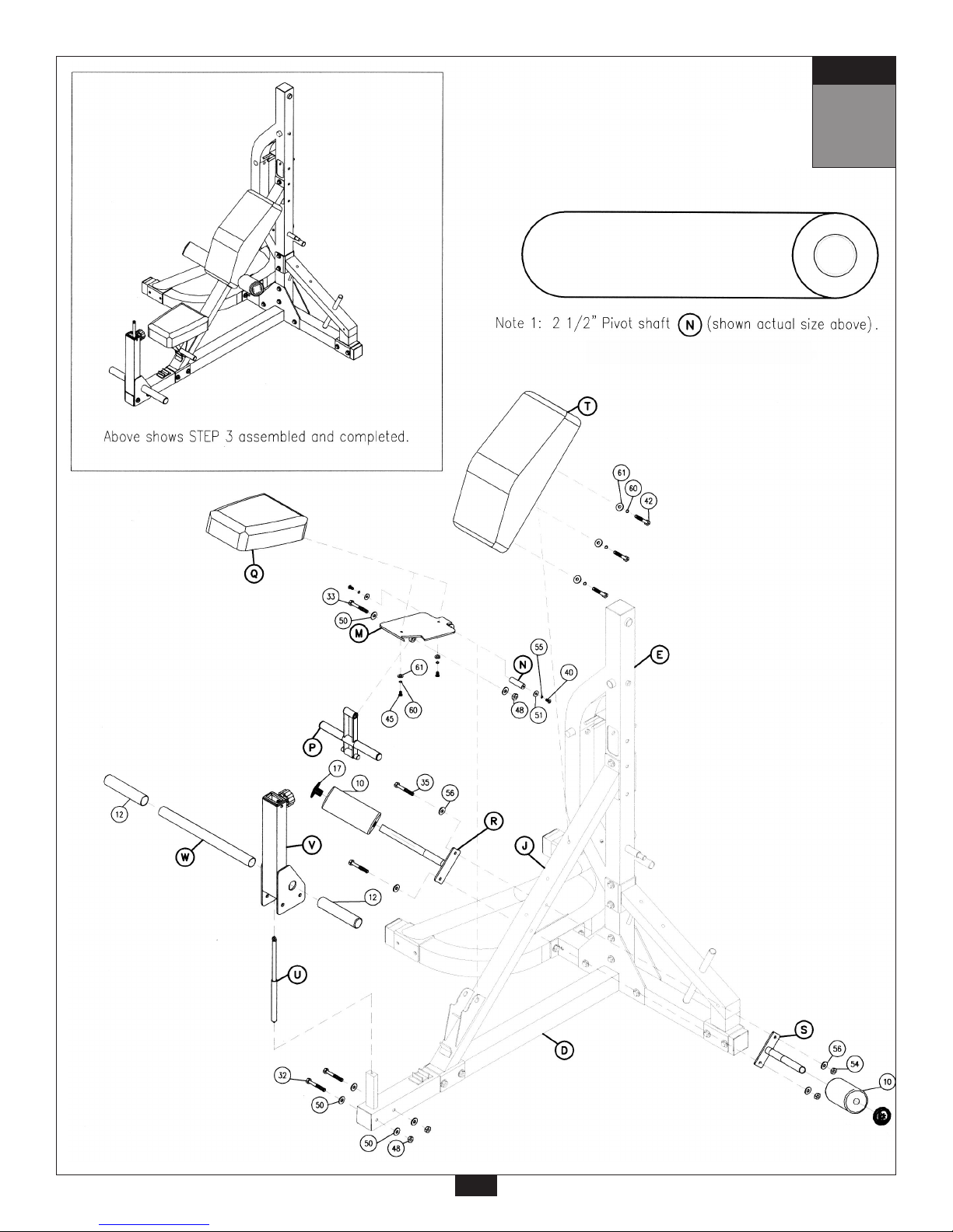
STEP
3
Be careful to assemble all components
in the sequence they are presented.
A. Open hardware package labeled “Step 3”.
B. Install seat pad frame (M) into lat support frame (J). See Note 1. Install 2 1/2” pivot shaft (N) to connect the
seat pad frame and the lat support frame. Secure as shown by using:
two 40 (round allen head10mm x 20mm full thread bolt)
two 55 (spring lock washer 10mm)
two 51 (flat washer 10mm x 30mm)
C. Attach seat adjustor (P) to the flanges beneath the seat pad frame (M) using:
one 33 (hex bolt 12mm x 95mm partial thread)
two 50 (flat washer 12mm)
one 48 (nylon lock nut 12mm)
D. Attach hold down brackets (R) and (S) to lat support frame (J).
Note: hold down brackets should be angled UP (not down). Install using:
two 35 (hex bolt 10mm x 100mm partial thread)
four 56 (flat washer 10mm)
two 54 (nylon lock nut 10mm)
E. There is a threaded end at the bottom of shock cylinder (U). Screw the threaded end of the shock
cylinder (U) into the post protruding from the lat base frame (D) as shown. Tighten by hand until snug.
F. Install preacher support (V) over the shock cylinder (U) and secure it to lat base frame (D) as shown using:
two 32 (hex bolt 12mm x 105mm partial thread)
four 50 (flat washer 12mm)
two 48 (nylon lock nut 12mm)
G. Insert foot hold down bar (W) thru the base of the preacher support (V) and hold in place by installing
both rubber foot covers (12) as shown.
H. Install back pad (T) on to lat support frame (J). Tighten pad bolts to a snug fit. Do not over-tighten any pad
bolts. Over - tightening pad bolts will cause T - nuts in pads to strip out. Install using:
three 42 (hex bolt 8mm x 70mm full thread)
three 60 (spring lock washer 8mm)
three 61 (flat washer 8mm)
I. Install seat pad (Q) on to seat pad frame (M). Tighten pad bolts to a snug fit. Do not over - tighten any pad
bolts. Over - tightening pad bolts will cause T - nuts in pad to strip out. Install using:
two 45 (round allen head 8mm x 20mm full thread bolt)
two 60 (spring lock washer 8mm)
two 61 (flat washer 8mm)
J. Slide both foam rollers (10) on to hold down brackets (R) and (S). Secure each foam roller in place by
inserting a round plastic end cap (17).
Note: At this point you should wrench tighten all hardware in Step 3 except the seat pad and
back pad bolts. Never wrench tighten any pad bolts.
11
mm
Inch
12
STEP
3

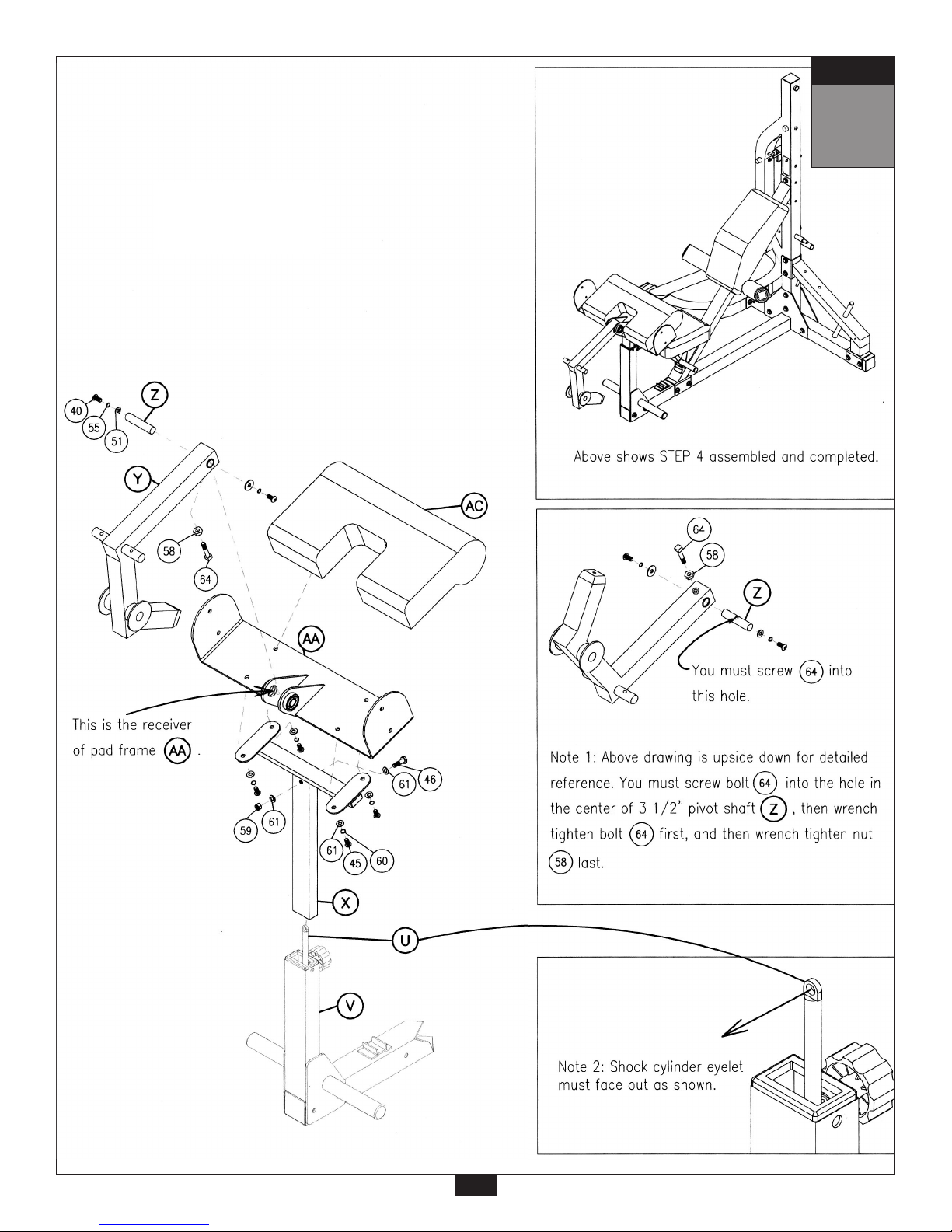
STEP
4
Be careful to assemble all components
in the sequence they are presented.
A Open hardware package labeled “Step 4”.
B. See Note 1. Install preacher pivot arm (Y) in to receiver of pad frame (AA). Install 3 1/2” pivot shaft (Z) to
connect the preacher pivot arm and the pad frame. Secure as shown using:
two 40 (round allen head 10mm x 20mm full thread bolt)
two 55 (spring lock washer 10mm)
two 51 (flat washer 10mm x 30mm)
one 58 (standard nut 8mm)
one 64 (square head bolt 8mm x 30mm with dog point)
C. Obtain assistance for this step. Align preacher post (X) with pad frame (AA) and preacher pad (AC).
Bolt together using:
four 45 (round allen head 8mm x 20mm full thread bolt) *
four 60 (spring lock washer 8mm)
four 61 (flat washer 8mm)
*
Note: Do not over-tighten these bolts. Tighten these bolts to a snug fit. Over - tightening these
bolts will cause T - nuts in pads to strip out.
See Note 1
D. See Note 2. Obtain assistance for this step. Insert preacher post (X) into preacher support (V).
Install bolt (46) (hex bolt 8mm x 40mm full thread) all the way thru preacher post eyelet of shock cylinder
and lock in place using two (61) (flat washer 8mm) and one (59) (nylon lock nut 8mm).
Note: After assembly, you should check all functions to ensure correct operation. If you experience problems, first recheck the assembly instructions to locate any possible errors made during assembly. If you are unable to correct the problem, call the dealer from whom you purchased
the machine or call 1-800-556-3113 for the dealer nearest you.
13
mm
Inch
14
STEP
4

STEP
5
Be careful to assemble all components
in the sequence they are presented.
A. Open hardware package labeled “Step 5”.
B. Attach both side arm pads (AB) to pad frame (AA) as shown using:
four 45 (round allen head 8mm x 20mm full thread bolt) *
four 60 (spring lock washer 8mm)
four 61 (flat washer 8mm)
*
Note: Tighten these bolts to a snug fit. Never wrench tighten any pad bolts.
C. Slide both preacher handles (AD) over welded shaft on preacher pivot arm (Y) as shown.
D. Secure preacher handles (AD) on to welded shaft by installing two (47) (flat allen head 8mm x 20mm full
thread bolt) in the direction shown into the threaded holes of the welded shaft on the preacher pivot arm (Y).
E. At this point you should lock preacher handles to preacher pivot arm by installing as shown;
two 40 (round allen head 10mm x 20mm full thread bolt)
two 55 (spring lock washer 10mm)
two 51 (flat washer 10mm x 30mm)
F. Slide 20" preacher weight post (AX) into preacher pivot arm (Y) as shown.
G. Slide both Olympic adapter sleeves (4) over the 20" preacher weight post (AX) as shown and
lock in place using:
two 51 (flat washer 10mm x 30mm)
two 55 (spring lock washer 10mm)
two 40 (round allen head 10mm x 25mm full thread bolt) *
*
Note: You should wr
ench tighten
these bolts now. You will need two (6mm) allen wrenches for this step.
To lock Olympic adapter sleeves in place, use both allen wrenches at the same time and turn them
in opposite directions to tighten.
H. Slide both rubber donuts (21) over Olympic adapter sleeves and press both plastic ball-end caps 2” (5)
into the ends as shown.
Note: After assembly, you should check all functions to ensure correct operation. If you
experience problems, first recheck the assembly instructions to locate any possible errors made
during assembly. If you are unable to correct the problem, call the dealer from whom you
purchased the machine or call 1-800-556-3113 for the dealer nearest you.
15
mm
Inch
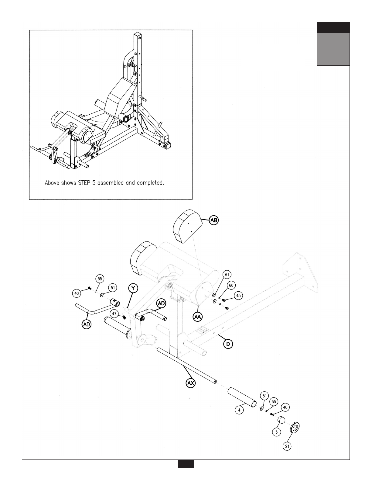
STEP
5
16

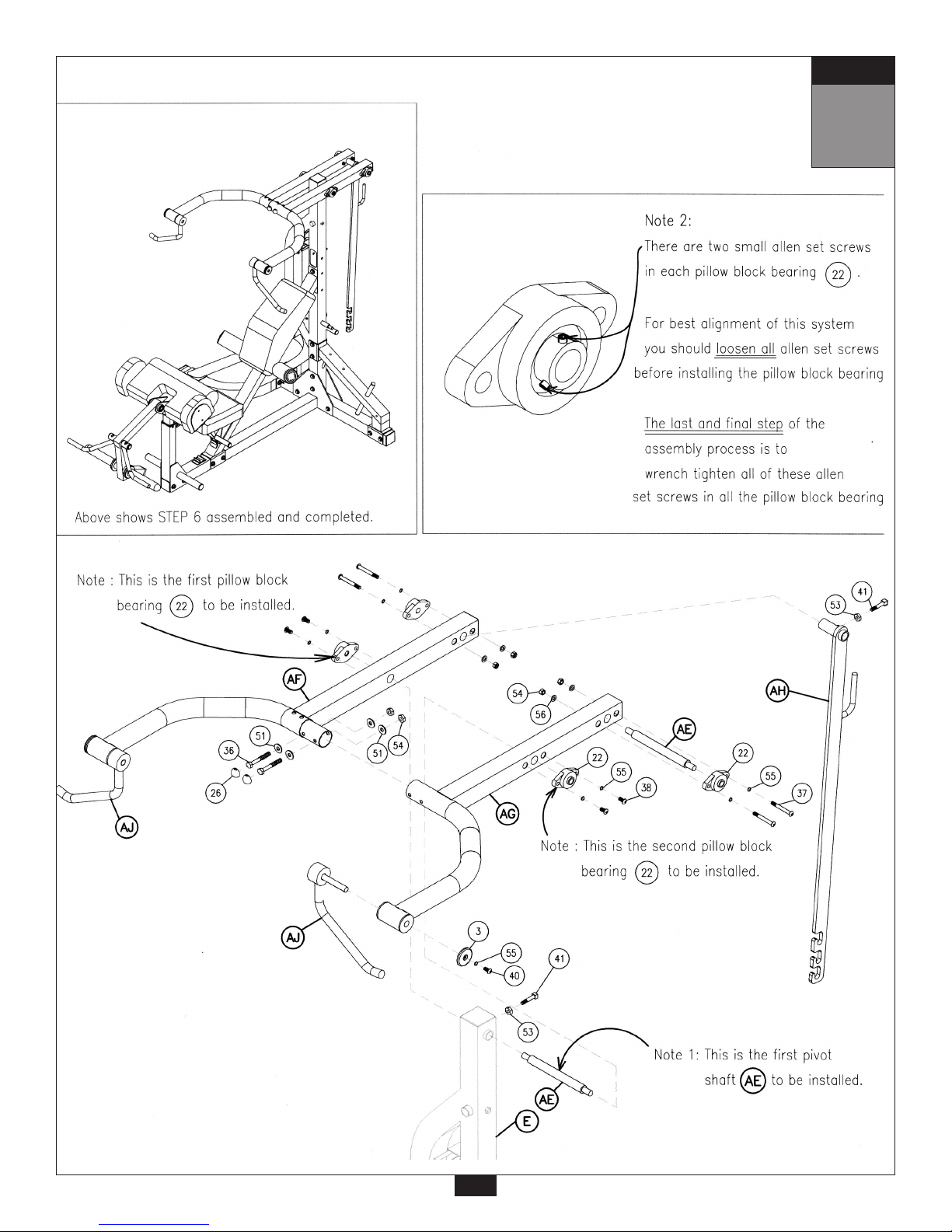
STEP
6
Be careful to assemble all components
in the sequence they are presented.
A. Open hardware package labeled “Step 6”.
B. See Note 1. Insert front pivot shaft (AE) into vertical mainframe (E) as show using:
one 41 (square head bolt 10mm x 55mm with dog point) *
one 53 (standard nut 10mm)
* Note: Be sure that (41) bolt goes into the hole in the center of the front pivot shaft (AE) and wrench
tighten (41) bolt first and then wrench tighten (53) nut last. It may be necessary to “feel” for the hole
in the center of the shaft by sliding a very small diameter allen wrench all the way thru first to help
you line up the parts.
C. Slide left lat beam (AF) on to the front pivot shaft (AE). See Note 2. Install pillow block bearing (22) on
to left lat beam (AF) as shown using:
two 38 (round allen head 10mm x 30mm full thread bolt)
two 55 (spring lock washer 10mm)
D. Slide right lat beam (AG) on to the front pivot shaft (AE). See Note 2. Install the other pillow block bearing (22)
on to the right lat beam (AG) as shown using:
two 38 (round allen head 10mm x 30mm full thread bolt)
two 55 (spring lock washer 10mm)
E. Secure left and right lat beams together (finger tighten only) by using:
two 36 (hex bolt 10mm x 75mm partial thread)
four 51 (flat washer 10mm)
two 54 (nylon lock nut 10mm)
F. Center the chrome lat adjustment bar (AH) between the left lat beam and right lat beam. Slide the rear
pivot shaft (AE) thru the right lat beam (AG) and then thru the chrome lat adjustment bar (AH), and then
thru the left lat beam (AF).
G. Install bolt (41) (square head bolt 10mm x 55mm with dog point) and nut (53) (standard nut 10mm) into the
threaded hole on the back side of the chrome lat adjustment bar (AH) as shown. *
* Note: Be sure that (63) bolt goes into
the hole in the center of the rear pivot shaft (AE) and wrench
tighten (63) bolt first and then wrench tighten (53) nut last. It may be necessary to “feel” for the hole
in the center of the shaft by sliding a very small diameter allen wrench all the way thru first to help
you line up the parts.
H. See Note 2. Install both pillow block bearings (22) onto each side of the rear pivot shaft (AE) as shown using:
four 37 (hex bolt 10mm x 85mm partial thread)
four 55 (spring lock washer 10mm)
four 56 (flat washer 10mm)
four 54 (nylon lock nut 10mm)
I. Install both lat handles (AJ) into left and right lat beams as shown using:
two 3 (black lat end cap 2.75” x 0.375”)
two 55 (spring lock washer 10mm)
two 40 (round allen head 10mm x 20mm full thread bolt)
Note: At this point you should close the gap between the left and right lat beams at their connection
point. Use a rubber mallet to knock the two parts together tightly.
You should now wrench tighten all bolts in this step.
J. Install two plastic bolt end covers (26) over bolts (36).
17
mm
Inch
Note:
You will need assistance in doing this step to properly align all parts.
Do not wrench tighten until instructed to do so.
18
STEP
6

STEP
7
Be careful to assemble all components
in the sequence they are presented.
A. Open hardware package labeled “Step 7”.
B. See Note 1. Install weight carriage (AK) onto pivot shaft that is welded to vertical mainframe (E).
C. See Note 2. Install pillow block bearing (22) on to weight carriage (AK). Secure as shown using:
two 38 (round allen head 10mm x 30mm full thread bolt)
two 55 (spring lock washer 10mm)
D. Slide 23" lat weight post (AY) into weight carriage (AK).
E. Slide both Olympic adapter sleeves (4) over 23" lat weight post (AY). Install as shown by using:
two 51 (flat washer 10mm x30mm)
two 55 (spring lock washer 10mm)
two 40 (round allen head 10mm x 20mm full thread bolt) *
two 5 (plastic ball-end cap 2")
two 21 (rubber donut)
* Note: You should wr
ench tighten these bolts now. You will need two (6mm) allen wrenches for this step.
To lock Olympic adapter sleeves in place, use both allen wrenches at the same time and turn them in
opposite directions to tighten.
F. Install pulley (9) into opening of vertical mainframe (E) as shown. Impor
tant: be sure that pulley spacers
are in place and are flush on each side of the pulley. Install using:
one 66 (hex bolt 10mm x 90mm partial thread)
two 56 (flat washer 10mm)
two 52 (zinc bushing 10mm)
one 54 (nylon lock nut 10mm)
G. Install cable (62) by feeding the plain eye end of the cable over the pulley as shown.
Then, attach snap link to plain eye end of cable and to hole in flange of weight carriage (AK).
Note: After assembly, you should check all functions to ensure correct operation. If you
experience problems, first recheck the assembly instructions to locate any possible errors made
during assembly. If you are unable to correct the problem, call the dealer from whom you
purchased the machine or call 1-800-556-3113 for the dealer nearest you.
19
mm
Inch
 Loading...