

Page 1

©2017 Powerley, LLC. or it s affi liates. All ri ghts reser ved. Powerley and
the Powerle y logo are trad emarks of Pow erley, LLC. and its af fi liates.
i
Powerley Thermostat
Installation & Operation Guide
Page 2

After a quick installation, your new Powerley Thermostat will allow you
to monitor and control your HVAC system from any where in the world.
The average homeowner spends up to 50% of their energy costs on
HVAC use. With the Powerley Thermostat , you'll have a great opportunit y
to reduce those costs by intelligently managing temperature setpoints .
To take full advantage of features such as setpoint scheduling, use the
companion app on your iOS or Android device to connect your Powerley
Thermostat to your Energy Bridge.
It is recommended to hire a profes sional HVAC installer. However, if you
do opt to install on your own, we'll guide you along the entire process.
Let's get started!
Welcome!
21
Page 3

Powerley Thermostat Installation & Operation Guide 20
Contents
Quick Start
Getting to Know your Thermostat 2
Installation 4
Thermostat Setup 10
Setup Troubleshooting 11
Compatibility 12
Step 4
Set up your therm ostat
schedule in th e app
Step 3
Use app to includ e the
Powerley Thermostat
Step 1
Take photo of existing
thermostat wiring
Step 2
Install Powerley Thermostat
Page 4
Powerley Thermostat Installation & Operation Guide 2
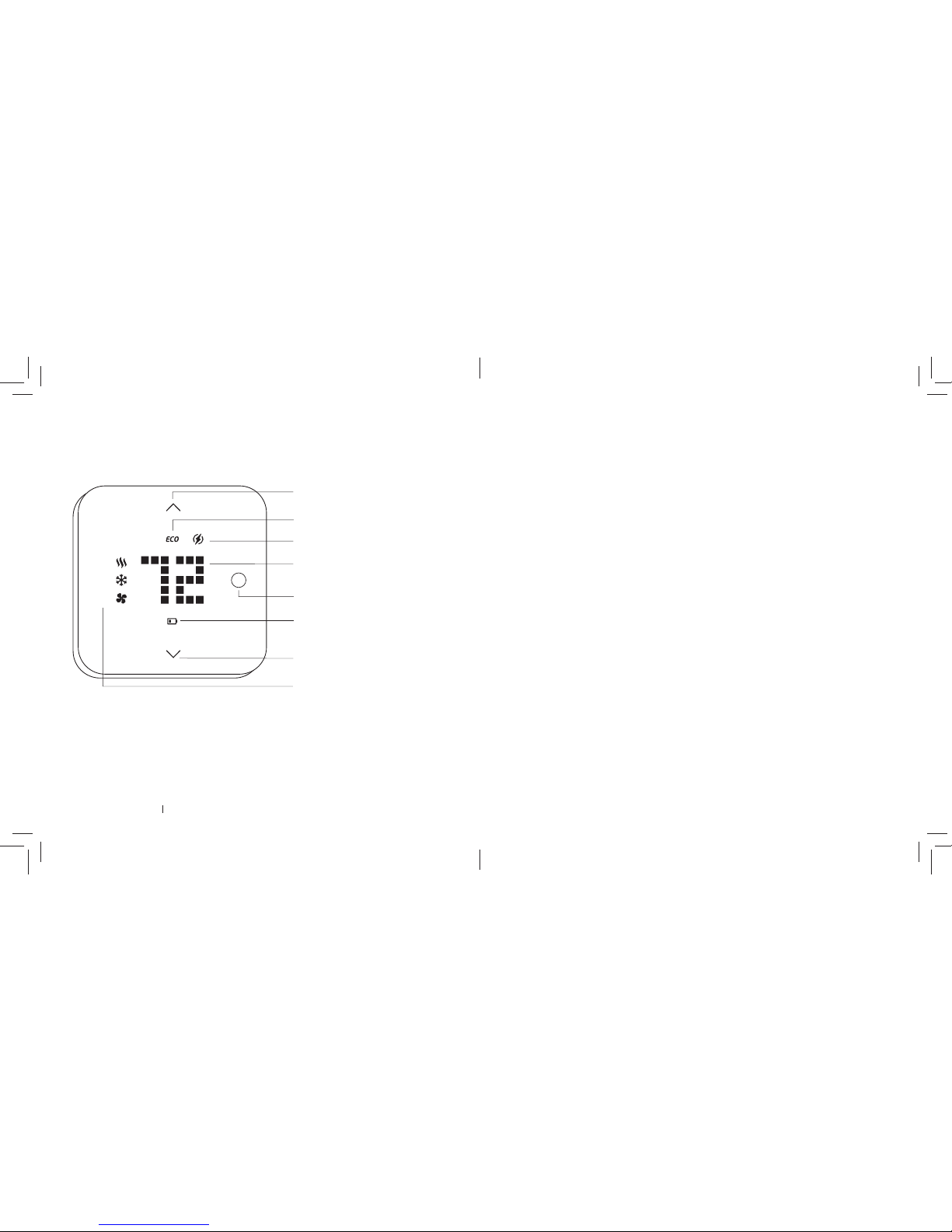
1.
2.
3.
Setpoint Down
Setpoint Up
Eco Mode Indic ator
Peak Demand Indicator
Temperature Display
Low Batter y Indicator
Mode
Mode Indicator:
1. Heat 2. Coo l 3. Fan
Getting to know your thermostat
19
Limitation of Damages
In addition to the ab ove warranty disclaime rs, in no event w ill Powerley be lia ble for any
conseque ntial, incidental , exe mplary, or special damag es, including any damage s for lost
data or lost p rofi ts, arisin g from or relating to this limited w arranty or the produc t, and
Powerley tot al cumulative liabilit y arising from or related to thi s limited warrant y or the
product w ill not exceed the am ount actually paid for the p roduct by the original pur chaser.
Disclaimer of Warranties
Except as state d above in this limited warrant y, and to the maximum extent perm itted
by applicable la w, Powerley discla ims all express , implied, and statutor y warranties and
conditions wit h respect to th e product, including the imp lied warranties of mercha ntability,
fi tness for a particula r purpose. To the max imum extent perm itted by applica ble law,
Powerley al so limits the dur ation of any implied w arranties or conditions to th e duration
of this limited war ranty.
Page 5

Powerley Thermostat Installation & Operation Guide 18
Limitation of Liability
Powerley dis claims all liability of a ny kind of Powerle y’s suppliers . The Powerley Thermos tat
Installation & O peration Guide contains an onlin e link for updated versions of t he operation
guide and sof tware product s/and or application(s) are availab le for added functio nality
(“Ser vices”) both of which provi de you differ ent information ( “Product Informatio n”) and
compatibility in formation reg arding use of the Powerley Th ermostat an d your HVAC
system in cluding the ty pe of product s that may be connected to y our thermos tat which
may change fr om time to time. The s ervices may be use d to control compatible H VAC
system vi a the product . Without limiting the gener ality of the disclaimers ab ove, all produc t
information i s provided fo r your convenience, “as is”, and “as av ailable”. Powerley does not
represent , warrant, or guarante e that product inf ormation will be available, a ccurate, or
reliable or that pr oduct information or use o f the serv ices or produc t will decrease the
energy con sumption of your home. You are so lely respo nsible for all en ergy bills incurred
by your home. You us e all product informatio n, the ser vices, and th e product at your own
discretion an d risk. You will be so lely respon sible for (and Powerley dis claims) any and
all loss, lia bility, or damage s, including to your HVAC system , plumbing, hom e, product,
product p eripherals, computer, mo bile device, an d all other items and p ets in your
home, res ulting from your u se of the produ ct information , services, or pro duct. Product
information p rovided by the s ervices is not intend ed as a substitu te for direct me ans of
obtaining the inf ormation. For example, a tem perature rea ding in the produc t information
provided b y the serv ices is not intend ed as a substit ute for reading t he temperatur e as
directly displ ayed by the produ ct.
3
• Setpoint Up/Down: All ow you to adjust yo ur thermost at setpoint.
• Eco Mode Indicat or: This LED will appe ar when you are in e nergy ef fi ciency mode.
• Peak Demand Indicator: This LED will appear when y ou are in a Peak De mand event.
• Mode: Press Mo de to wake the ther mostat up and c ycle betwe en modes.
• Low Batter y Indicator: If your therm ostat is oper ated on batteri es, this LED will ap pear
when batte ries need to b e replaced .
• Mode Indicators: The thermost at's current m ode will display he re.
Waking Up
To wake up your thermos tat, press M ode once. The di splay will light up with th e ambient
temperature a nd the Heat or Coo l mode indicator i f either is activ e.
Selecting Modes
To select a mod e, press Mo de repeatedly to c ycle between Heat , Cool , and Off mode.
Adjusting Setpoint s
To adjust the setpo int, fi rst make sure yo ur thermost at is in Heat or Cool mode
as indicated by t he mode indicato r. Tap the setpoint up or down arr ows to adjust to
your target s etpoint. Th e temperature di splay and mode in dicator will blink dur ing the
setpoint adjustm ent.
Once you' ve settled o n a mode and setp oint, you can ei ther press M ode (while the
display is blinkin g) to confi rm your selec tion or simply w ait for a few se conds to
automatically confi rm your sele ction and retur n to displaying ambi ent temperature .
Page 6

Powerley Thermostat Installation & Operation Guide 4
Installation
1. Important! Shut off power to HVAC system
Put your exist ing thermos tat in Off mo de, then shut of f power to your H VAC system
either at the circuit b reaker or the sy stem switch.
2. Take a picture of wiring for existing thermostat before removing it
Remove the fr ont of your existi ng thermos tat and take a pict ure of the wire
confi guration. Thi s will be your guide w hen installin g your new therm ostat. If
any wires are th e same color, be su re to mark them with t ape to identif y them.
CAUTION: Shut off main power to prot ect yours elf and your equi pment!
17
FCC Notice
This device com plies with Par t 15 of the FCC Rules . Operation i s subject to the f ollowing
two conditions:
1. This device m ay not cause har mful interf erence, and
2. T his device mus t accept any inter ference rece ived, includin g interfere nce that may
cause undesired operation.
Note
This equipme nt has been tested and f ound to comply wit h the limits for a Cla ss B digital
device, pur suant to Part 15 of the FCC Rules . These limits are desi gned to provid e reasonable
protectio n against harmful inter ference in a residenti al installatio n. This equipment gene rates,
uses and ca n radiate radio fr equency en ergy and, if not in stalled and used in accor dance with
the instruc tions, may cause harmf ul interference to radio co mmunications . However, there
is no guarante e that interference will not o ccur in a particular installati on. If this equipment
does caus e harmful interferenc e to radio or televi sion reception, which can b e determined by
turning the e quipment off a nd on, the user is encour aged to try to correct t he interfer ence by
one or more of th e following measure s:
• Reorient or r elocate the re ceiving antenn a.
• Increase th e separation b etween th e equipment and r eceiver.
• Connect th e equipment into an o utlet on a circuit diff erent from that to w hich the
receiver is connec ted.
• Consult the dea ler or an experie nced radio/ TV technici an for help.
Information to User
The users m anual or instru ction manual f or an intentional or unint entional radiator s hall
caution the us er that changes o r modifi cations no t expressly a pproved by the p arty
respons ible for complian ce could void the us er’s authorit y to operate the equipment .
Page 7
Powerley Thermostat Installation & Operation Guide 16
Installation Location
This thermo stat is for ind oor use only. It sh ould be mounte d on an inner wall ab out 5ft
(1.5m) abov e the fl oor at a positio n where it is read ily affec ted by changes of t he general
room temper ature with free ly circulating air. Avoid mo unting above or ne ar hot surfa ces
or equipment (e .g. TV, heater, refri gerator). Avoid mo unting where it w ill be expose d to
direct sunsh ine, draft s, or in a laundr y room or other e nclosed spa ce. Do not expos e this
unit to dripping or spla shing liquids .
Device Information
Purpose of Co ntrol: Operatin g Control
Construction of Control: Independently Mo unted Control
Pollution De gree: 2
Impulse Voltag e: 330 V
Room Thermostat
EN485122
5
3. Check Compatibility
Before contin uing to Step 4, check yo ur HVAC system compatibilit y on page 12. Once
you're sure yo ur system is co mpatible, remo ve the existing th ermostat fr om the wall.
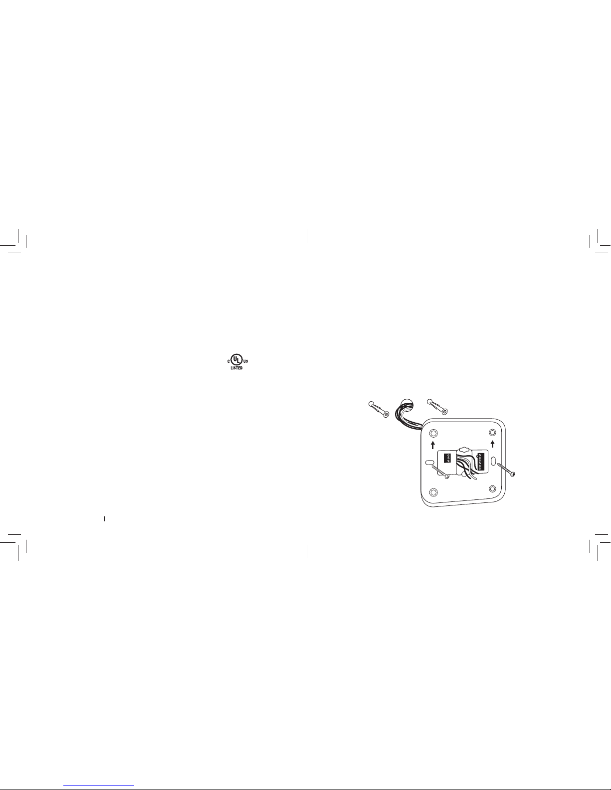
4. Mount Wallplate
To separate the wallpl ate from the ther mostat front , grasp the si des of the front w hile
holding the op ening in wallplate a nd pull apart .
Mount the wallpl ate using the scre ws and anchor s provided. I f necessar y, drill a 1/4-in
hole for dr ywall or 5/ 32-in h ole for plast er.
NOTE: Make sure the arrows o n the wallplate are fa cing up.
Page 8

Powerley Thermostat Installation & Operation Guide 6
5. Connect W ires (Conventional System)
A conventional o ne-stag e system usually has 4 -5 wires, wh ile a conventional m ulti-stage
system ha s 6-7 wires. U se the picture y ou took in Step 2 to dete rmine which colo r wire
goes to which ter minal. Refer to the w iring guide on th e next page to c onfi rm your
wiring confi guration.
Loosen the s crew by turning it co unterclockw ise and ins ert the wire on i nside edge
of the terminal b lock. Tighten t he screw by turnin g clockwis e to secure the w ire in its
terminal. Rep eat for remaini ng wires.
If you have a heat p ump system , refer to its us er manual for co rrect wire con fi guration.
See pg. 8 fo r the heat pump jump er confi guration g uide. You should confi gur e the heat
pump jumper pr ior to providing p ower to your The rmostat.
NOTE: Do not remove the m etal jumper b etween ter minal blocks RH an d RC unless you
have both RH and RC wires conne cted.
RH
RC
C
Y
Y2
G
W
W2
O/B
AUX
15
Caution!
• Do not modif y the unit in any way: Risk of fi re, electr ical shock, o r burns if modifi ed.
• Do not dispo se of electri cal appliances a nd unsorte d municipal was te, use separ ate
collection f acilities. Cont act your loca l government fo r information re garding the
collection s ystems ava ilable.
• There are no us er serv iceable par ts in this unit.
• Risk of explos ion if batter y is replace d by an incorrec t type. Di spose of us ed batterie s
according to th e instructi ons.
• Installatio n by a trained HVAC Technician is re commende d.
• Read all enclos ed instruc tions thoro ughly before i nstalling your n ew thermost at.
• Give specia l attention to all war nings, note s and installati on steps to minimize ri sk of
damaging the t hermostat o r the HVAC system.
• Label all wire s before dis connecting . Taking a picture is al so recommen ded in case
the old therm ostat must b e re-insta lled.
• Switch off pow er to your HVAC system e ither at the circuit bre aker or the sys tem
switch before installing.
Battery Safety
• Use new bat teries, pe r the specifi cation sheet.
• Never mix old an d new batter ies.
• Prevent leak ing by removin g dead batteri es when notifi ed.
• Recycle and s ave the environ ment.
Page 9

Powerley Thermostat Installation & Operation Guide 14
Wireless Information
This device ha s an open-air lin e-of-sight t ransmiss ion distance of 132 f eet (40m) which
complies with Z-Wave st andards. Pe rforman ce can vary d epending on th e amount of
object s in betwee n Z-Wave devices such as wa lls and furnitur e.
This produ ct can be oper ated in any Z-Wave netwo rk with other Z-Wave cert ifi ed
devices fr om other manuf acturers . All non-bat tery oper ated nodes w ithin the netw ork
will act as rep eaters regar dless of vendo r to increase relia bility of the net work.
Radio Freque ncy Limitations:
1. Each wall or obje ct (i.e.: ref rigerator, boo kshelf, large T V, etc) can re duce the
maximum ran ge of 65 feet (20 m) by up to 20 to 30%.
2. P lasterboa rd and woode n walls block les s radio signal than concrete, b rick or tile
walls which will h ave more of an ef fect on sig nal strength .
3. Wall mounted Z-Wave devi ces will also s uffer ran ge loss wh en housed i n metal
junction boxe s and could red uce the range by up to 20 -30%.
Maintenance
• Do not expos e your unit to dust , strong sunlight , humidity, high tem peratures or
mechanical shock.
• Do not use ol d and new batte ries togeth er as old batte ries tend to lea k.
• Do not use cor rosive or abr asive cleans ers on your unit .
• Use a water wet cl oth to clean the sof t plastic surface.
• Keep the unit dust f ree by wiping it w ith a soft, dr y cloth.
• Do not disas semble the unit .
7
Wiring Guide
*NOTE: If you do not have a C-wire, the t hermostat m ay be powere d by
installing (4) AA b atteries.
Symbols
Cool Change over (Heat Pump)
Heat Change over (Heat Pump)
1st Stage Heater
2nd Stage Heater
24Vac Power for Heatin g
24Vac Power for Cool ing
24Vac Com mon *
1st Stage Compr essor
2nd Stage Compr essor
1st Stage Fan
O
B
W1 or W
W2
RH
RC
C *
Y1 or Y
Y2
G
Ter mina ls
CAUTION: DO N OT install batteries with C-wire connected.
Page 10

Powerley Thermostat Installation & Operation Guide 8
6. Heat Pump Confi guration
If you have a heat p ump, you should c onfi gure the heat pum p jumper prior to p roviding
power to your T hermostat . The jumper is l ocated on the ba ck of the Thermo stat face,
in the lower lef t of the right-side opening . Pull the jumper s traight out to rem ove, then
confi gure according to yo ur heat pump t ype. See confi guration options below.
HEAT PUMP "B"
HEAT PUMP "B"
HEAT PUMP "0"
HEAT PUMP "0"
CONFIG 1: Ground Connection (Def ault)
Jumper
Jumper
Jumper
CONFIG 3: "B" ConnectionCONFIG 2: "0" Connection
13
Tec hn ic al Sp ecifi cations
• RF Frequenc y 915MHz (US)
• RF Operating D istance:
Up to 132ft (40m) outdo or line of sight, in u nobstruc ted environm ent
• Capacitive tou ch with white LEDs displ ay
• Status icons: 6
•
, , control butto ns and LEDs
• Powered B y: Dry bat tery AA x 4 pcs or 24 VAC +/20% 50/60 Hz
• Relay Contact Volt age: 24 VAC 50/60 Hz
• Current: 1A Max . (inductiv e)
• Temp Unit: °F / °C
• Temp Measurable Ran ge: -4°F to 185°F, -20°C to 85°C
• Humidity Rang e: 0 to 100% relative h umidity
• Temp Setting Range : 45°F to 90°F, 7°C to 32°C
• Temp Dead Band: 3° F, 4°F, 5°F or 6°F
• Operating Temp: 32° F to 131°F, 0°C to 55°C
• Storage: Temp: - 4°F to 176°F, -20°C to 80°C
• Dimensio n (L x H x T): 120mm x 120mm x 30m m
• Weight: 255g (B atteries exclu ded)
Page 11

Powerley Thermostat Installation & Operation Guide 12
Compatible HVAC Systems
• 24Vac single & 2-stage co nventional heat ing system s (gas, oil or el ectric)
• Heat pump sy stems with up to 2 st ages of heatin g (electric or g as)
• Boiler systems
• One or two s tage coolin g systems
Incompatible HVAC Systems
• Radiant fl oor and wall h eating syste ms
• Zoned forc ed air and zoned h ot water (2 or 3 wire)
• Hybrid sy stems/Du al-fuel sys tems
• Geotherm al systems
• Multi-zoned syste ms
• 110V or higher line vo ltage syst ems (e.g. elec tric baseb oard heaters)
• Millivolt sys tems (12-24Vac or DC source)
NOTE: Thick black, red , or white wires con nected with w ire nuts runni ng to existing
thermost at typicall y mean high volta ge system .
Compatibility
9
RC
RH
C
y2
Y
g
8. Switch on main power to your HVAC system
Once you have yo ur new thermo stat in place, p ower your HVAC syste m back on at
the circuit breaker o r system sw itch.
Press Mod e on your thermo stat to wake it up. It will dis play the current amb ient
temperature o nce it has power.
7. Attach thermostat to wallplate
Align the guide s from the ther mostat to the wa llplate and gently pr ess into place.
The magneti c closure will kee p the two pie ces secured .
CAUTION: DO N OT install batteries with C-wire connected.
Page 12

Powerley Thermostat Installation & Operation Guide 10
Thermostat Setup
1. Launch Setup
You're now read y to connect your P owerley The rmostat to you r Energy Bridg e! Launch
the app and be gin thermos tat setup, which w ill guide you thro ugh the setup pr ocess.
2. Z-Wave Inclusion Process
First, b e sure your Energ y Bridge has p ower and the gre en light is illuminated. Follow the
in-app instr uctions alo ng with the step s below to include y our Thermos tat.
To put your thermos tat into inclusio n mode, pres s and hold Mo de for 5 secon ds.
• CONNECT will scroll acro ss the therm ostat display on ce in inclusion mo de.
• SUCCESS will scroll acros s the thermo stat display once i ncluded.
• FAIL wi ll scroll acros s the thermos tat display if inclus ion is unsucce ssful, or if pr ocess
takes long er than 1 minute. Se e the next pag e for trouble shooting.
To learn more abo ut which Z-Wave command clas ses this the rmostat sup ports , visit:
www.powerley.com/thermostat/command-classes
Hold for 5 se conds
11
Setup Troubleshooting
If you are exper iencing issu es with connec tivity and/o r controlling the the rmostat
from the app, it m ay be neces sary to exclud e and re-includ e the thermos tat to your
Z-Wave network. I f these iss ues persi st, fact ory rese t the thermos tat and retr y the
inclusion proces s.
Z-Wave Exclusion Process
To exclude your Therm ostat, pre ss and hold Mo de for 5 seco nds to initiate Z-Wave
exclusion proces s.
• DELETE will scroll across th e thermost at display once in exclu sion mode.
• To cancel the exclusio n process , press Mod e.
• To complete exclusion p ress either o f the up/down arrow s.
• SUCCESS will scroll acros s the thermo stat display once ex cluded.
NOTE: Excluding the the rmostat will r estore it to the def ault state for Z-Wave and
temperature s et points.
Factor y Reset
Please us e Factory Re set only when th e network p rimary contr oller is missin g or
otherw ise inoper able. To reset to fac tory def aults, turn th e thermost at off by pres sing
Mode repeat edly until OFF scrolls acr oss the displa y, then press and h old the down an d
up Setpoint arro ws at the same tim e for 5 sec. If su ccessful , RESET will scroll acro ss the
display and the d evice will be res tored to its def ault settings.
NOTE: If a reset to fac tory def ault setting s is perfor med, all set tings includin g Z-Wave
confi guration param eter values an d temperature s etpoints will re turn to default val ues:
Heat: 68 Cool: 78 Measure: Fahrenheit Swing : +/- 1 Multi-stage temp differential: 3
System Type: 2-stage conventio nal heating & cooli ng
 Loading...