

PowerLand PD3G4400E, PD3G10000E, PD3G6500E, PD3G8500E Owner's Manual
Owner’s Manual
Full Power Output Panel
SERIES GASOLINE, LPG, NG POWER
This manual provides information regarding the operation and maintenance of these
products. We have made every effort to ensure the accuracy of the information in this manual.
We reserve the right to change this product at any time without prior notice.
Please keep this manual available to all users during the entire life of the GASOLINE, LPG,
NGgenerator.

SPECIFICATIONS
ItemPD3G4400EPD3G6500EPD3G8500EPD3G10000E
Rated Wattage3500W5500W7000 W8000W
Surge Wattage4400W6500W8500W10000W
Rated Voltage120/240V
Rated Frequency60Hz
PhaseSingle
G e n e r a t o r
DC OutputDC 12V/8.3 A
Engine type4-stroke OHV single cylinder with forced air cooling system
Ignition systemTransistorized magneto
Spark Plug NGK BPR6ES, F7RTC
Engine Speed3600 rpm
Compression Ratio8.5 : 18.0 : 1
Displacement208 cc419 cc
Starting typeElectric start /Recoil
Use clean, fresh, regular LPG with LPG gaspressurearea: 10~15
PSI.
Use clean, fresh, regular Natural Gaswith NG gas pressurearea:
0.25 PSI.
Fuel
Use gasoline with a pump octane rating of 86 or higher
Oil capacity
0.63 US qt
(0.6 L)
1.2 US qt (1.1 L)
Engine oil gradeSAE 10W30 SG or SF or SN
Valve Clearance
Intake 0.10-0.15 mm (0.004– 0.006 in.)
Exhaust 0.15-0.20 mm (0.006– 0.008 in.)
E n g i n e
Noise Level75 dB @ 7 m (22 feet)
Dimensions (in):
28"×21.6"×
22.6"
30.2"×22.5"×24.2"
30.3"X28.7"X
25.2"

WARNING:
The generator is a potential source of electrical shock if misused. Do not expose the
generator to moisture, rain or snow. Do not let the generator get wet, and do not operate
it with wet hands.
Keep this owner's manual handy, so you can refer to it at any time. This owner’s manual is
considered a permanent part of the generator and should remain with the generator if resold.
Congratulations on your selection of our generator. We are certain you will be pleased with your
purchase of one of the finest generators on the market.
We want to help you get the best results from your new generator and to operate it safely. This
manual contains the information on how to do that, please read it carefully.
As you read this manual, you will find information preceded by a symbol. That information is
intended to help you avoid damage to your generator, other property, or the environment.
When your generator needs scheduled maintenance, keep in mind that our servicing dealer is
specially trained in servicing our generators. Your authorized our servicing dealer is dedicated
to your satisfaction and will be pleased to answer your questions and concerns.
A FEW WORDS ABOUT SAFETY
Your safety and the safety of others is very important. And using this generator safely is an
important responsibility.
To help you make informed decisions about safety, we have provided operating procedures
and other information on labels and in this manual. This information alerts you to potential
hazards that could hurt you or others.
Of course, it is not practical or possible to warn you about all the hazards associated with
operating or maintaining a generator. You must use your own good judgment.
You will find important safety information in a variety of forms, including;
·Safety Labels—on the generator.
·Safety Messages —Preceded by a safety alert symbol and one of three signal words,
DANGER, WARNING, or CAUTION.
These signal words mean:
DANGER: You WILL be KILLED or SERIOUSLY HURT if you don't follow instructions.
WARNING: You WILL be KILLED or SERIOUSLY HURT if you don't follow instructions.
CAUTION: You CAN be HURT if you don't follow instructions.
·Safety Headings — such as IMPORTANT SAFETY INFORMATION.
·Safety Section— such as GENERTOR SAPETY.
·Instructions — how to use this generator correctly and safely.
This entire book is filled with important safety information — please read it carefully.
Theengineexhaustfromthisproduct
containschemicalsknowntotheState of
Californiatocausecancer,birth defects
orotherreproductiveharm.

CONTENTS
SAFETY ........................……………………………………………………………………........ 1
Safety Label Locations ...................... …………………………………………………..........1
Safety Information ............................ …………………………………………………………....1
COMPONENT IDENTIFICA TION ......................…………………………………………………3
CONTROLS ..................…………………………………………………………………………..4
Engine Switch ................………………………………………………………………………..4
Recoil Starter ………………………………………………………....................... …….........…4
Fuel Valve Lever ……………………………………………………………………………………4
Choke Rod ..…………………………………………………………………………………..... 5
Voltage Selector Switch (Dual V oltage System) ............... ……………………….............. 5
Ground Terminal ................................................................................ ………….............. 6
DC T erminal ........................................................................................ …………..............6
DC Circuit Protector ...............……………………………………………………………………..6
Oil Alert System ................... ……………………………………………………………..........6
AC Circuit Breaker.... ………………………………………………………………………………7
AC Circuit Protector…………………………………………………………………………………8
Auto Throttle System…………………………………………………………………………………8
GENERATOR USE ................................…………………………………………………………9
Connections to a Building Electrical System..........................…………………………………9
Ground System ................................................................................... ………………………9
AC Applications .................................................................................. ………………………9
AC Operation ...................................................................................... ………………………9
AC Receptacle Selection .................................................................... ……………………… 10
DC Operation ...................................................................................... ……………………… 11
PRE-OPERATION CHECK........................... …………………………………………………12
Engine Oil ................................ …………………………………………………………………12
Fuel Recommendation ................................ …………………………………………………13
STARTING THE ENGINE/STOPPING THE ENGINE .............. ………………….................17
MAINTENANCE ................................ ……………………………………………………………19
The Importance of Maintenance ................................ ………………………………………19
Maintenance Safety ................................ ………………………………………………………20
Emission Control System Information ................................ …………………………………20
Air Index ........................................................ ………………………………………...............22
Maintenance Schedule ................................ …………………………………………………22
Engine Oil Change ................................ ………………………………………………………23
Air Cleaner Service ................................………………………………………………………23
Fuel Sediment Cup Cleaning ..............................………………………………………………24
Spark Plug Service ................................ ………………………………………………………24
Spark Arrester Maintenance................... ………………………………………………………25
TRANSPORTING/STORAGE............ ……………………………………………………………26
ASSEMBLY ....…………………………………………………………………………………………28
TROUBLESHOOTING...............................…………………………………………………………29
Grounding Requirements for Power Land Portable Generators…………………………………31
WIRING DIAGRAM ................................ …………………………………………………………34
EXPLODED VIEW AND P ARTS LIST ....... …………………………………………………………38

1
SAFETY
SAFETY INFORMATION
Our generators are designed to give safe and dependable service if operated according to
instructions. Reed and understand this owner's manual before operating your generator. You
can help prevent accidents by being familiar with your generator's controls, and by observing
safe operating procedures.
Operator Responsibility
·Know how to stop the generator quickly in case of emergency.
·Understand the use of all generator controls, output receptacles, and connections.
·Be sure that anyone who operates the generator receives proper instruction. Do not let
children operate the generator without parental supervision.
Carbon Monoxide Hazards
·Exhaust contains poisonous carbon monoxide, a colorless and odorless gas. Breathing
exhaust can cause loss of consciousness and may lead to death.
·If you run the generator in an area that is confined, or even partially enclosed, the air you
breathe could contain a dangerous amount of exhaust gas. To keep exhaust gas from
building up, provide adequate ventilation.
Electric Shock Hazards
·The generator produces enough electric power to cause a serious shock or electrocution if
misused.
·Using a generator or electrical appliance in wet conditions, such as rain or snow, or near a
pool or sprinkler system, or when your hands are wet, could result in electrocution. Keep the
generator dry.
·If the generator is stored outdoors, unprotected from the weather, check all electrical
components on the control panel, before each use. Moisture or ice can cause a malfunction
or short circuit in electrical components which could result in electrocution.
·Do not connect to a building's electrical system unless an isolation switch has been installed
by a qualified electrician.

2
Fire and Burn Hazards
·The exhaust system gets hot enough to ignite some materials.
— Keep the generator at least 1 meter (3 feet) away from buildings and other equipment
during operation.
— Do not enclose the generator in any structure.
— Keep flammable materials away from the generator.
·The muffler becomes very hot during operation and remains hot for a while after stopping the
engine. Be careful not to touch the muffler while it is hot. Let the engine cool before storing
the generator indoors.
·Gasoline is extremely flammable and is explosive under certain conditions. Do not smoke or
allow flames or sparks where the generator is refueled or where gasoline is stored. Refuel in
a well-ventilated area with the engine stopped.
·Fuel vapors are extremely flammable and may ignite after the engine has started. Make sure
that any spilled fuel has been wiped up before starting the generator.
·Always keep fuel away from sparks, open flames,pilot lights, heat and other sources of
ignition.
·DO NOT light or smoke cigarettes.
WARNING:When use the LPG generator, if find any problems(LPG leakage or strange
smells), please turn off the gas source immediately and then check the connection
hose to insure the safely.
WARNING: 1. When using the LPG/Gasoline generator, please be sure that there is at least 5
feet distance between LGP tank connecting hose and the generator, to prevent
unnecessary danger because of high temperature surface of LGP tank.
2. When using the unit, please check the surface temperature of LPG tank.
3.Don't place the LPG tank in one place where ambient temperatureabove35℃
and use LPG for electricity generating.
3
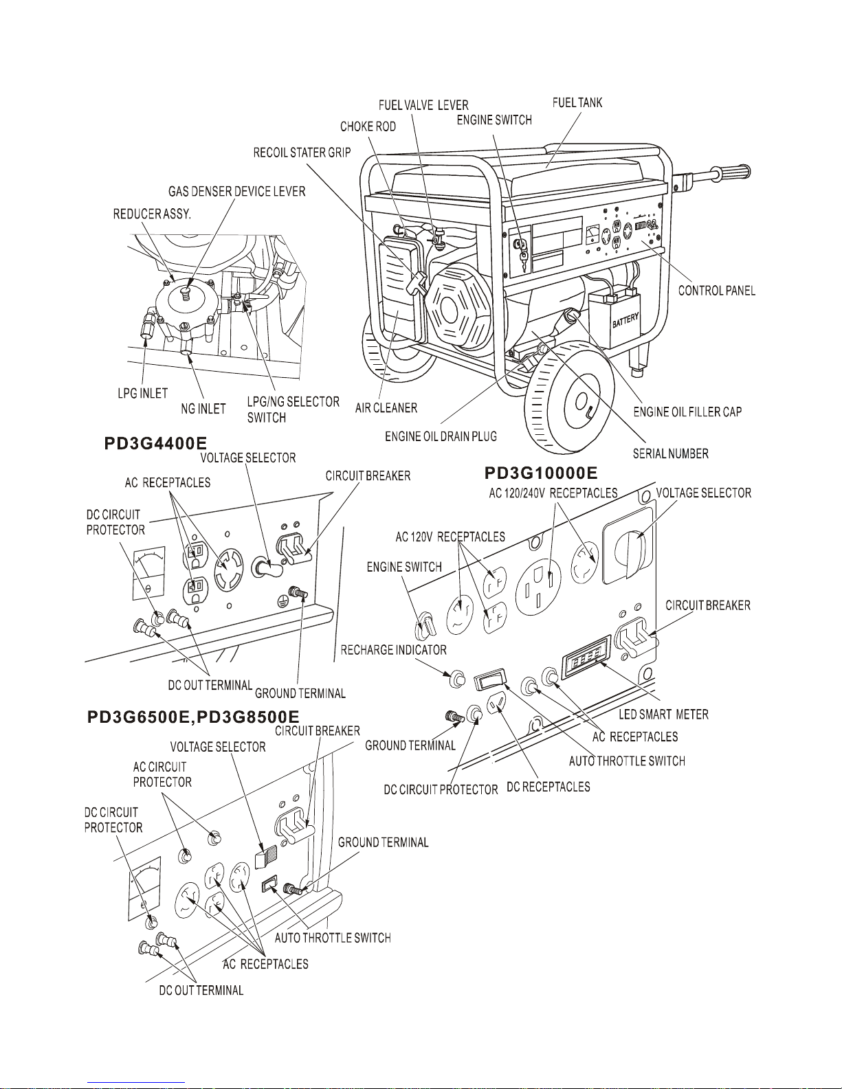
COMPONENT IDENTIFICATION
Record the engine and frame serial
numbers for your future reference. Refer
to these serial numbers when ordering
parts, and when making technical or
warranty inquiries.
4
CONTROLS
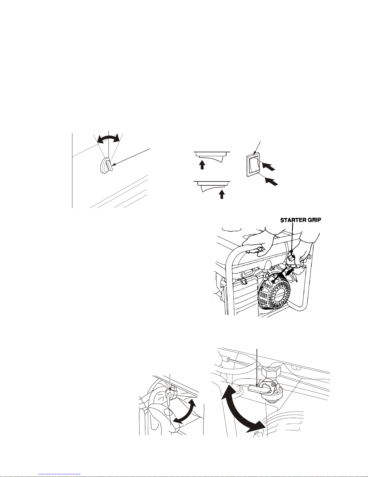
Engine Switch
To start and stop the engine
Switch position:
OFF: To stop the engine. Keycanbe
r
e m o v e d / i n s e r t e d .
O N :
T o r u n t h e e n g i n e a f t e r s t a r t i n g .
START: To start the engine by operating the starter motor.
O F F
O N
O F F
O N
E N G I N E S W I T C H
O F F
E N G I N E S W I T C H
O F F
O N
S T A R T
Recoil Starter
Turn engine switch to “ON”
To start the engine, pull the starter grip lightly until
resistance is felt, then pull briskly.
NOTICE:Do not allow the starter grip to snap back
against the engine. Return it gently to
prevent damage to the starter.
The recoil starter is used to start the engine if the
generator is not equipped with a 12 volt battery to
operate the starter motor, or if the battery does not
contain adequate charge to operate the starter motor.
Fuel Valve Lever
The fuel valve is located
between the fuel tank and
carburetor. When the fuel
valve lever is in the ON
position, fuel is allowed to flow
from the fuel tank to the
carburetor. Be sure to return
the fuel lever to the OFF
position after stopping the
engine.
O N
F U E L V A L V E L E V E R
O F F
O F F
O N
F U E L V A L V E L E V E R
5
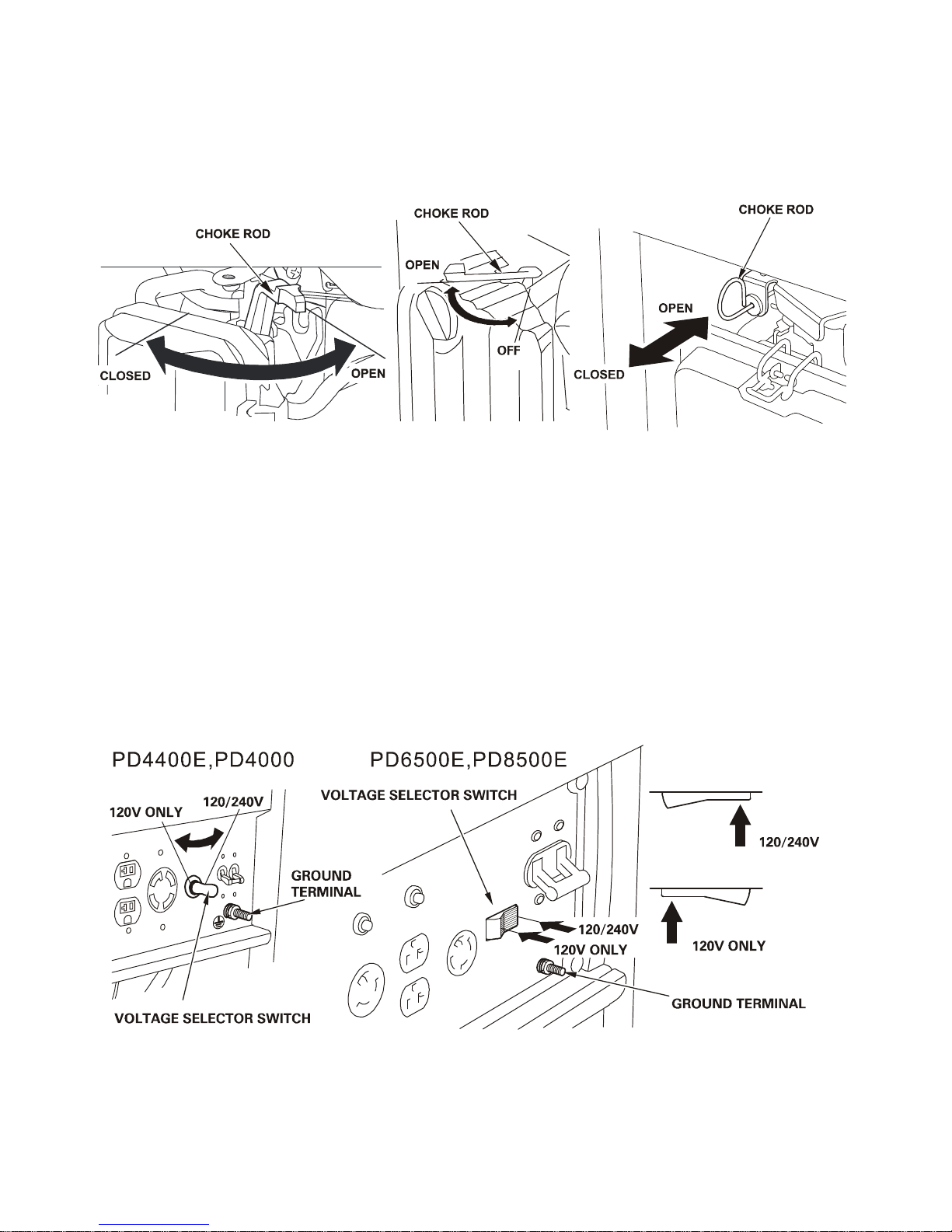
Choke Rod
The choke is used to provide an enriched fuel mixture when starting a cold engine. It can be
opened and closed by operating the choke lever manually. Move the chokeleveror pull the
choke rod out to the CLOSED position to enrich the mixture for cold starting.
Voltage Selector Switch
The voltage selector switches the main power carrying windings of thegenerator to produce
"120V ONLY" or "120/240V". If a 240V applianceis connected to the 4-prong receptacle, the
switch must be in the "120/240V" position. If only a 120V appliance is being connected to any
ofthe 120V 3-prong receptacles, select the "120V ONLY" position.
120/240V: The 120V and 120/240V receptacles can be used simultaneously.120V
Receptacles only can output half of the rated power.
120V ONLY: ONLY the 120V receptacles can be used. Do not use the 120/240V receptacle
in this position. Rated power will be available at the 120V twist lock receptacle.
The most power will be available at the 30A 120V locking plugreceptacle.
WARNING:Change the Voltage Selector Switch after turning the AC circuit
breaker to OFF. The generator may be damaged.

6
Before using the ground
terminal, consult a qualified
electrician, electrical
inspector or local agency
having jurisdiction for local
codes or ordinances that
apply to the intended use of
the generator.
DC Terminals
The DC terminals may ONLY
be used for charging 12 volt automotivetype batteries.
The terminals are colored, red will identify the positive (+) terminal and black will identify the
negative (-) terminal. The battery must be connected to the generator DC terminals with the
proper polarity (battery positive must be connected to the generator red terminal and battery
negative must be connected to the generator black terminal).
N E G A T I V E T E R M I N A L
( B L A C K )
P O S I T I V E T E R M I N A L
( R E D )
D C C I R C U I T
P R O T E C T O R
O F F
O N
O F F
O N
D C C I R C U I T
P R O T E C T O R
N E G A T I V E T E R M I N A L
( B L A C K )
P O S I T I V E T E R M I N A L
( R E D )
DC Circuit Protector
The DC circuit protector automatically shuts off the DC battery charging circuit when the DC
charging circuit is overloaded, when there is a problem with the battery, or when the connections
between the battery and the generator are improper.
Oil Alert System
The Oil Alert System is designed to prevent engine damage caused by an insufficient of oil in
the crankcase. Before the oil level in the crankcase can fall below a safety limit, the oil alert
system will automatically stop the engine (the engine switch will remain in the ON position). If
the engine stops and will not restart, check the engine oil level before troubleshooting in other
areas.
1 2 0 / 2 4 0 V
1 2 0 V O N L Y
V O L T A G E S E L E C T O R S W I T C H
1 2 0 V O N L Y
1 2 0 / 2 4 0 V
G R O U N D T E R M I N A L
7
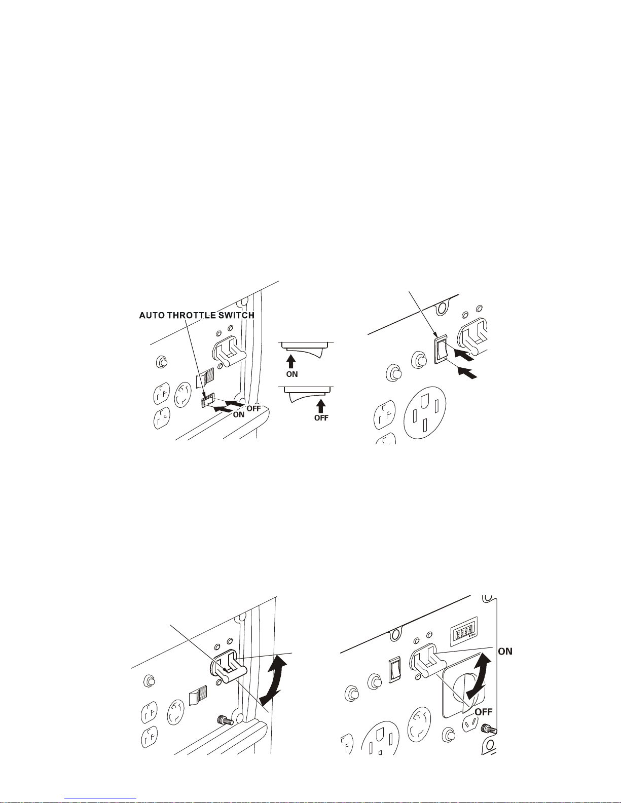
Auto Throttle System
The auto throttle system automatically reduces engine speed when allloads (i.e.: tools and
appliances) are turned off or disconnected. When loads are turned onor reconnected, the
engine returns to the rated speed.
Switch Position
ON: Recommended to minimize fuel consumption and further reduce noise levels when no
load is applied to the generator. The auto throttle system does not operate.
OFF: Recommended to minimize warm-up time when the generator is started and starting load
with large start-up power equipments.
*NOTICE: If connect to a residence, it is recommended that the auto throttle be kept in the
“ON” position if less than 50% load is being used. If the generator will be running over
50% it is recommended that you switch to the “OFF” position.
O F F
O N
A U T O T H R O T T L E S W I T C H
AC Circuit Breaker
The circuit breaker must be in the “ON” position in order to start running a load, but it will
automatically switch “OFF” if there is a short circuit or a significant overload of the generator at
the receptacle. If the circuit breaker is switched OFF automatically, check that the appliance is
working properly and does not exceed the rated load capacity of the circuit before switching the
circuit breaker ON again.
*The circuit breaker may be used to switch the generator power ON or OFF.
O F F
O N
A C C I R C U I T B R E A K E R
PD3G4400E
PD3G10000E

8
AC Circuit Protector
The AC circuit protectors will
automatically switch OFF if there is a
short circuit or a significant overload of
the generator at the 20A 120V,30A 120V
locking plug, or 120/240V locking plug
receptacle. If a ACcircuit protector
switches OFF automatically, check that
the applianceis working properly and
does not exceed the rated load capacity
of thecircuit before resetting the AC
circuit protector ON.
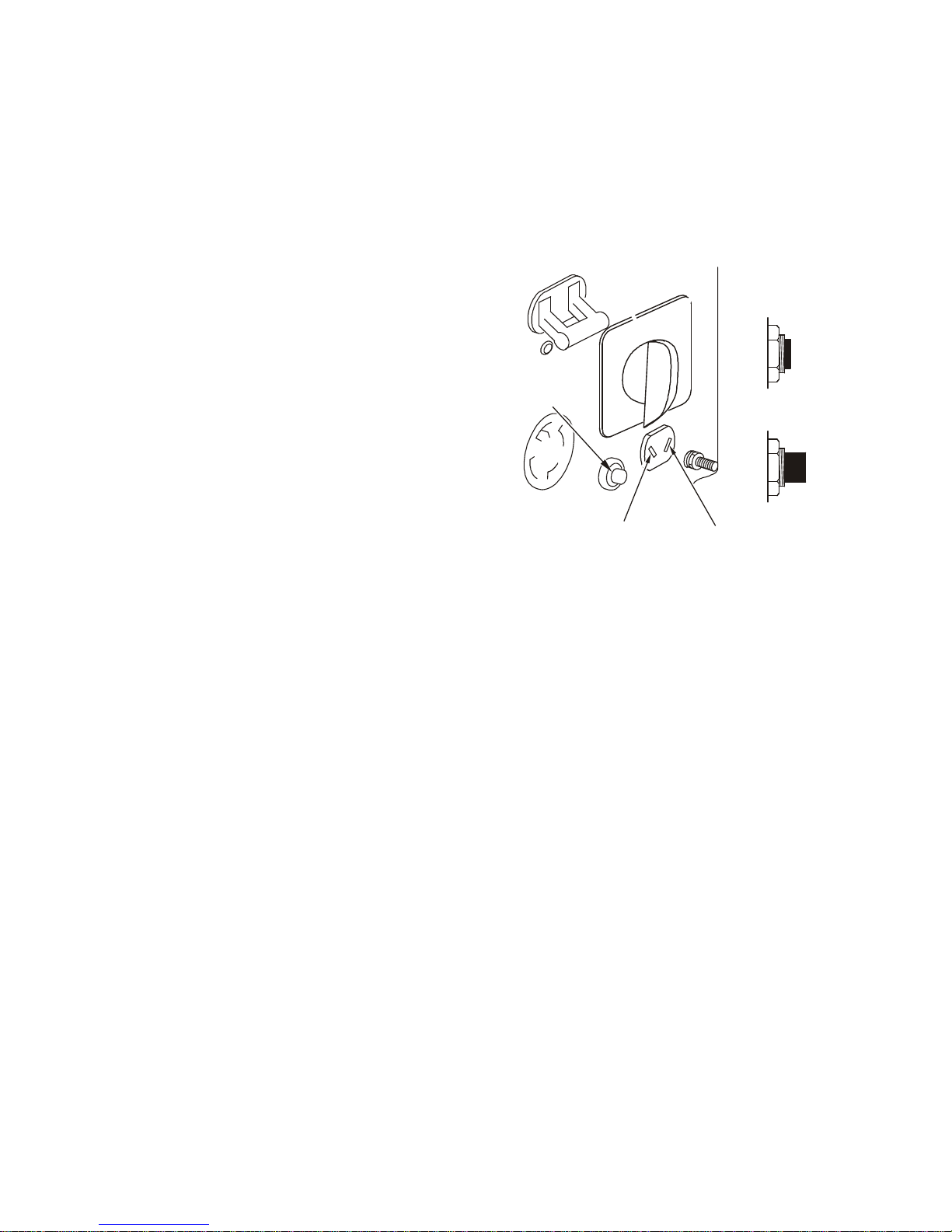
Gas Denser Device
To develop cold start performance of LPG/NG generator unit, the air REDUCER ASSY includes
one gas denser device lever, the detailed operation of the bottom is as below.
Choose the connector according to the gas you use:
●If you use LPG, you need to put the LPG hose to the LPG inlet, make the NG inlet screw
and seal well with the nut and turn the LPG/NG selector switch to LPG position.
●If you use NG, you need to put the NG
hose to the NG inlet, make the LPG inlet
screw and seal well with the nut and turn
the LPG/NG selector switch to the NG
position.
When start the cold LPG/NG generator unit,
open the valve of LPG tank orNGsource, close
the resistance air valve handle, push the gas
denser device lever lightly, and keep 1-2
seconds, then stop,and thenstart the engine
normally.
CAUTION: Improper treatment or use of the
generator candamage it, shorten its
life and void yourwarranty
●Thegas denser device lever only does
work after turning on the gas source valve, if start normally, no need pull the lever,
otherwise it will cause generator unit work abnormally;
●When push the gas denser device lever, the keeping time must not over 2 seconds,
otherwise it is not good for start;No need to push the gas denser device lever at every
start, only need to use when the first start of the cold generator unit or when need to
change Gas;
●If with abnormality, please contact us;
●Prohibit adjusting the LPG gas-pressure adjusting screw and gas flow adjusting screw.
PD3G8500E

9
GENERATOR USE
Connections to a Building Electrical System
Connections for standby power to a building electrical system must be made by a qualified
electrician. The connection must isolate the generator power from utility power, and must
comply with all applicable laws and electrical codes.
WARNING: Improper connections to a building electrical system will allow electrical current from
the generator to back feed into the utility lines. Such back feedwill electrocute utility
company workers or others who contact the lines during a power outage, and the
generator may explode, burn, or cause fires when utility power is restored. Consult the
utility company or a qualified electrician.
Ground System
Generators have a system circuit that connects generator frame components to the ground
terminals in the AC output receptacles. The system circuit is not connected to the AC neutral
wire. If the generator is tested by a receptacle tester, it will show the same ground circuit
condition as for a home receptacle.
AC Applications
Before connecting an appliance or power cord to the generator:
•Make sure that it is in good working order. Faulty appliances or power cords can become
hazardous and cause electrocution.
•If an appliance begins to operate abnormally, operates sluggish or stops suddenly, turn it
off immediately. Disconnect the appliance, and determine whether the problem is the
appliance, or if the rated load capacity of the generator has been exceeded.
•Make sure that the electrical rating of the tool or appliance does not exceed that of the
generator. Never exceed the maximum power rating of the generator. Power levels
between rated and maximum may be used for no more than 30 minutes
NOTICE:Substantial overloading will open the circuit breaker. Exceeding the time limit for
maximum power operation or slightly overloading the generator may not switch the
circuit breaker or circuit protector OFF, but will shorten the service life of the
generator.
Limit operation requiring maximum power to 30 minutes. For continuous operation (longer than
30 minutes), do not exceed the rated power.The total power requirements (kW) of all
appliances connected must be considered. Appliance and power tool manufacturers usually list
rating information near the model number or serial number.
AC Operation
1. Start the engine.
2. Turn the voltage selector switch to either position.
10
With the voltage selector switch in the ‘‘120/240V’’ position, you can use the 120V and
120/240V receptacles simultaneously. If you are NOT using the 120/240V receptacle, but
require more power from the 120V locking plug receptacle, then select the ‘‘120V ONLY’’
position.
3. Switch the AC circuit breaker ON.
4. Plug in the appliance.
Most motorized appliances require more than their rated power for startup.
Do not exceed the current limit specified for any one receptacle. If an overloaded circuit causes
the AC circuit breaker or AC circuit protector to switch OFF, reduce the electrical load on the
circuit, wait a few minutes and then reset the AC circuit breaker or AC circuit protector.
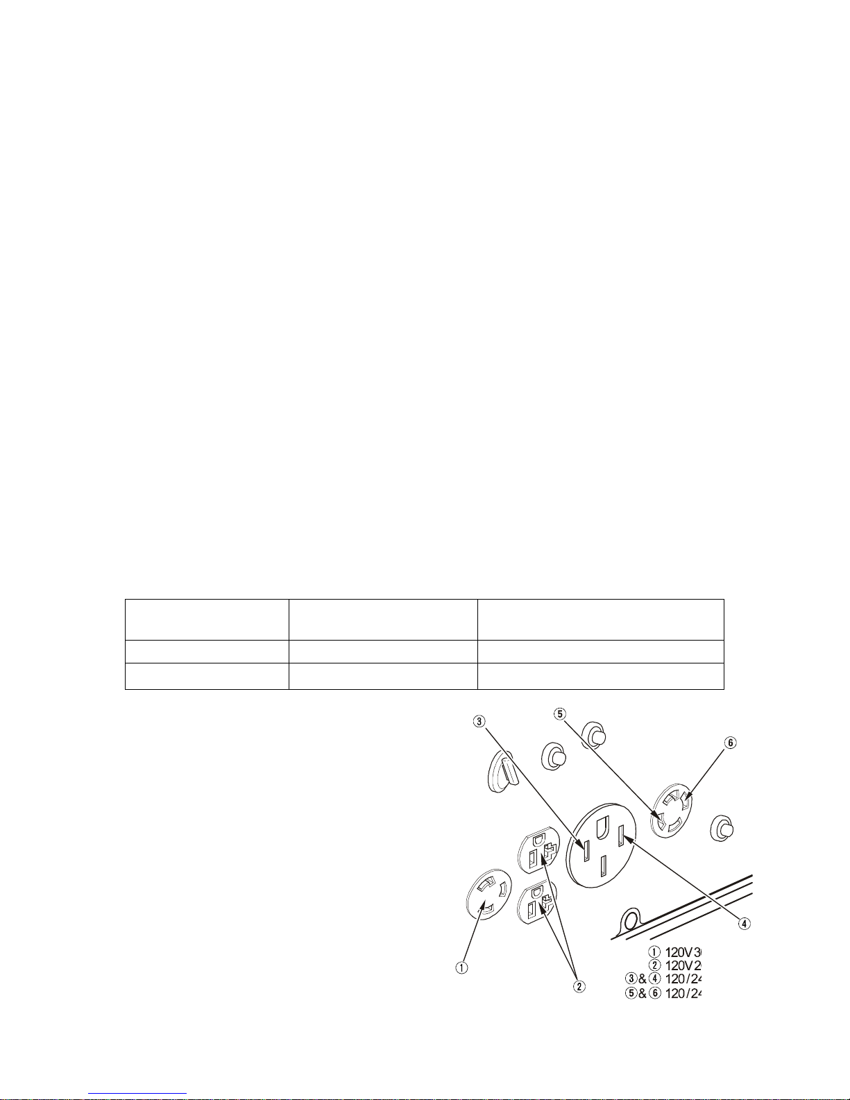
AC Receptacle Selection
The generator has two separate main power producing circuits. These two circuits supply equal
power to different receptacles shown when the voltage selector switch is in the 120/240V
position.
When two or more receptacles are used; to prevent overloading, dividing the load between the
two power circuits.
Example:
The chart below shows the rated load in amperes that can be connected to each receptacle to
balance the generator.
For Example, we have one model of generator whose total rated ampere draws65A.
Main power circuit
Receptacles powered by
each main circuit
Power distribution
Main Circuit I2, 4 and 6
2+4+6=32.5A rated.
Main Circuit II1,3 and 5
1+3+5=32.5A rated.
The table shows the specifications when the
120/240V locking plug receptacle is used for
120V.
Receptacle 1 has a 20A load connected to it.
Receptacle 3 has a 15A load connected to it. Both
receptacles are powered by mainpower circuit II.
The equation tells us that the total power draw on
circuit II is 35A. This is a substantial overload of
this circuit. Toeliminate the excess power draw on
circuit II, the load fromreceptacle 3 should be
switched to receptacle 2. Now circuit I ispowering
the 20A load (less than 32.5A) and circuit II is
powering
a
1 5 A
load(lessthan32.5A).
11
DC Operation
The DC terminals may ONLY be used for charging 12 volt automotivetype batteries.
Connecting the battery cables:
1. Before connecting the battery charging cables to a battery that is
installed in a vehicle battery, disconnect the vehicle ground battery cable from the battery
negative (-) terminal.
WARNING:The battery gives off explosive
gases; keep sparks, flames and
cigarettes away. Provide adequate
ventilation when charging or using
batteries.
Battery posts, terminals and related
accessories contain lead and lead
compounds. Wash hands after
handling.
2. Connect the positive (+) battery cable to
the automotive battery positive (+)terminal.
3. Connect the negative (-) battery cable to
the automotive battery negative (-)terminal.
4. Make sure circuit breaker is off.
5. Start the generator.
NOTICE:Do not start the vehicle while the battery charging cable isconnected and the
generator is running. The vehicle or the generator may be damaged.
An overloaded DC circuit, excessive current draw by the battery, or a wiring problem will trip the
DC circuit protector (PUSH button extends out). If this happens, wait a few minutes before
pushing in the circuit protector to resume operation. If the DC circuit protector continues to go
OFF, discontinue charging and see your authorized generator dealer.
Disconnecting the battery cables:
1. Stop the engine.
2. Disconnect the negative (-) battery cable from battery.
3. Disconnect the positive (+) battery cable from battery.
Auto Throttle System
With the switch in the ON position, engine speed is automaticallyreduced when ALL loads are
turned OFF or disconnected. Whenappliances are turned ON or reconnected, the engine
returns to ratedspeed. In the OFF position, the auto throttle system does not operate.
O F F
O N
D C C I R C U I T
P R O T E C T O R
N E G A T I V E T E R M I N A L
( B L A C K )
P O S I T I V E T E R M I N A L
( R E D )
 Loading...