

Page 1

CUBIC MACHINE SCREW JACK
HIGH DUTY, METRIC
“SYM-METRIC” - SERIES
(MECHANICAL LINEAR ACTUATORS)
SPARES LIST &
MAINTENANCE
INSTRUCTIONS
MANUAL : MM-SMS-E-02
SUPPLIED BY: POWER JACKS LIMITED
Page 2
Sym-metric Series – Screw Jacks
CONTENTS
1 UNIT DETAILS ....................................................................................................................................................................... 2
2 PERFORMANCE RATINGS ................................................................................................................................................. 3
2.1 P
ERFORMANCE OF STANDARD SYM-METRIC ACTUATORS ...................................................................................................... 3
2.2 S
YM-METRICACTUATOR EFFICIENCIES ................................................................................................................................... 3
3 GENERAL INSTRUCTIONS ................................................................................................................................................. 4
3.1 M
4 RECOMMENDED LUBRICANTS ........................................................................................................................................ 4
5 GENERAL ASSEMBLY & PARTS LIST ............................................................................................................................. 5
5.1 G
5.2
5.3 PARTS LIST ............................................................................................................................................................................. 6
6 DISASSEMBLY / ASSEMBLY INSTRUCTIONS (D.A.I.) ................................................................................................. 7
6.1 T
6.2 ROTATING SCREW D.A.I. ....................................................................................................................................................... 8
7 WARRANTY INFORMATION ............................................................................................................................................. 9
7.1 L
7.2 WARRANTY ............................................................................................................................................................................ 9
AINTENANCE AND INSTALLATION RECOMMENDATIONS. ..................................................................................................... 4
ENERAL ARRANGEMENT – PART A ...................................................................................................................................... 5
GENERAL ARRANGEMENT – PART B ........................................................................................................................................ 6
RANSLATING SCREW D.A.I .................................................................................................................................................. 7
IMITATION OF RESPONSIBILITY ............................................................................................................................................ 9
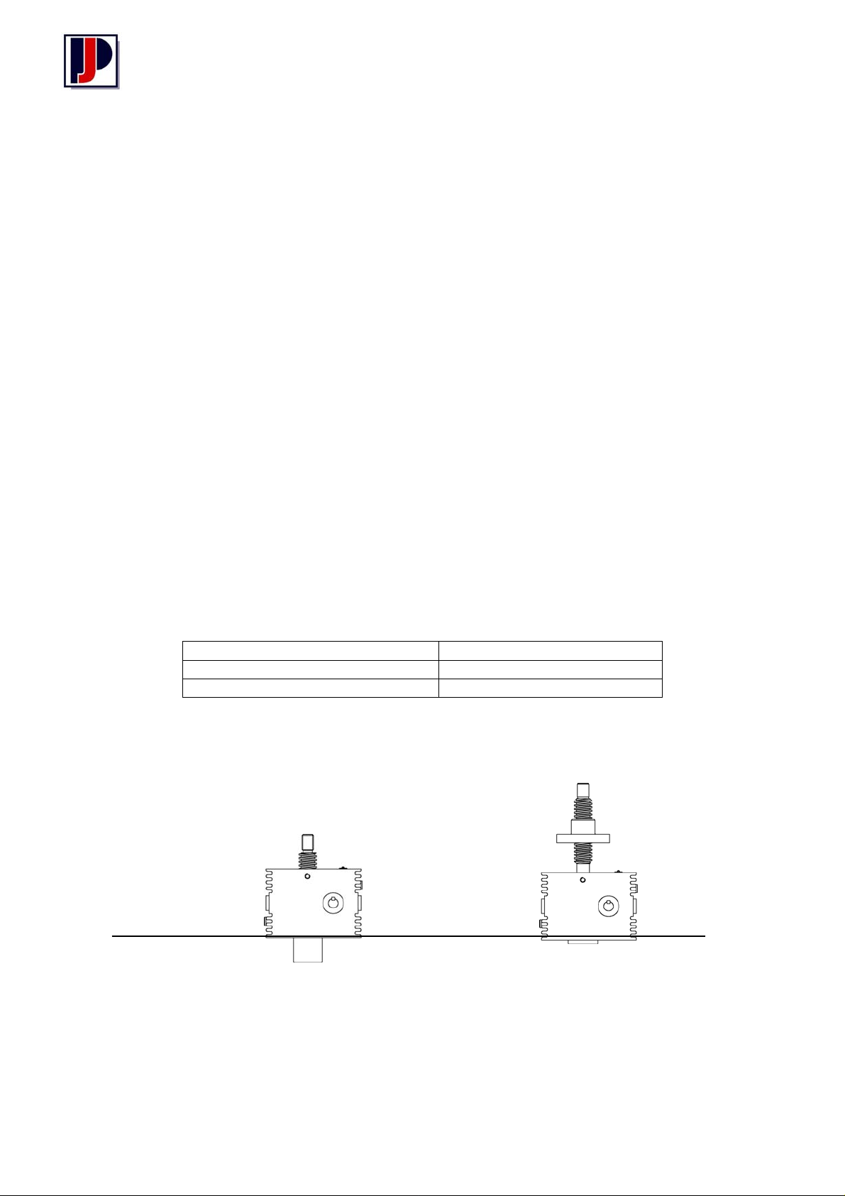
1 Unit Details
Serial Number
Model Number
Power Jacks Sales Order Number
Translating Screw
(Upright and Inverted)
2
Rotating Screw
(Upright and Inverted)
Page 3
Sym-metric Series – Screw Jacks
2 Performance Ratings
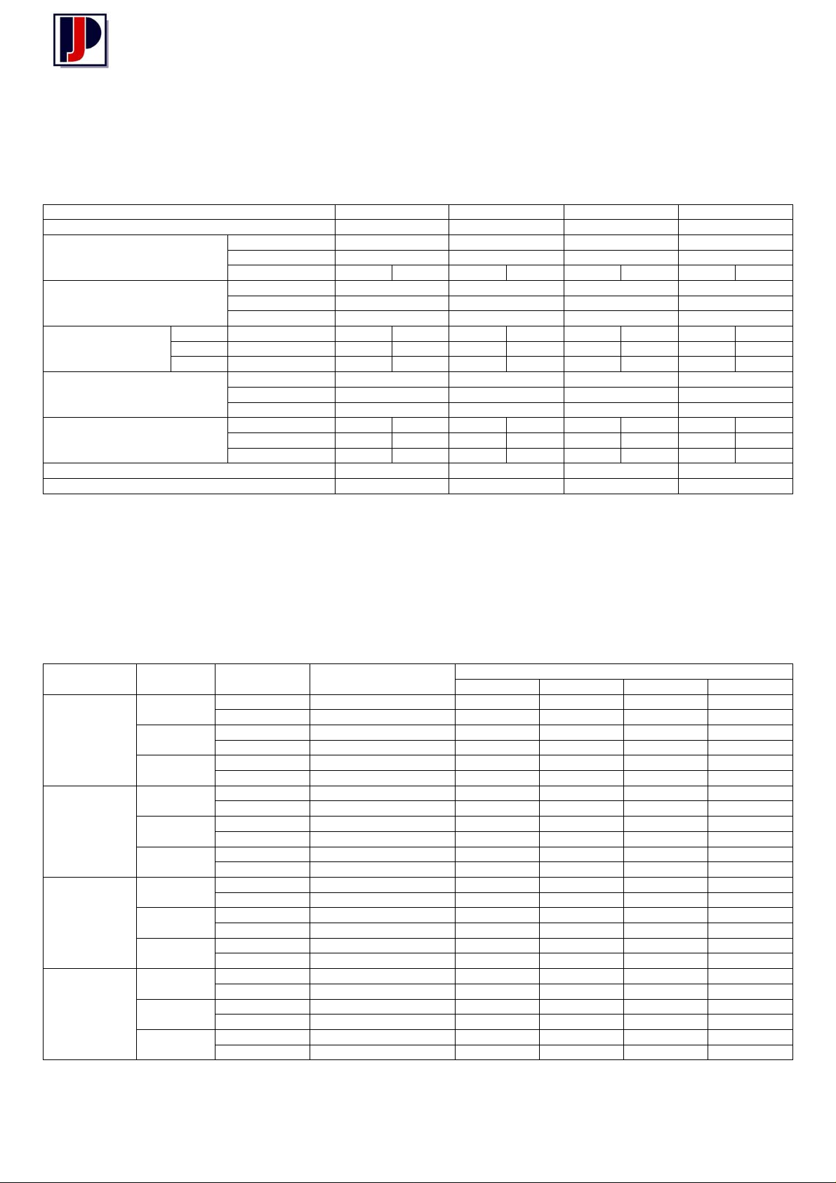
2.1 Performance of Standard Sym-metric Screw Jacks
Actuator Model ST025 ST050 ST100 ST200
Capacity (kN) 25 50 100 200
Diameter Ø30 Ø40 Ø50 Ø65
Lifting Screw
Worm Gear Ratios
Turn of worm for
raise of lifting screw
Maximum Input Power per
Actuator (kW)
Start-Up Torque
at full Load (Nm) †
Weight with base raise of 150mm (kg) 13 25 41 70
Weight for each additional 25mm raise (kg) 0.21 0.32 0.57 0.86
1 Turn Standard 1mm 2mm 1.5mm 3mm 1.5mm 3mm 1.5mm 3mm
4 Turn Option 1 3mm 6mm 4.5mm 9mm 8mm 16mm 8mm 16mm
4 Turn Option 2 1mm 2mm 1.5mm 3mm 2mm 4mm 2mm 4mm
*
Single start lifting screw is standard.
† For loads of 25% to 100% of actuator capacity, torque requirements are approximately proportional to the load.
2.2 Sym-metric Screw Jack Efficiencies
Pitch 6 mm 9 mm 12 mm 12 mm
No of Starts* 1 2 1 2 1 2 1 2
Standard 6:1 6:1 8:1 8:1
Option 1 8:1 8:1 6:1 6:1
Option 2 24:1 24:1 24:1 24:1
Standard 1.5 3.0 3.75 3.75
Option 1 1.5 3.0 3.75 3.75
Option 2 0.375 0.550 1.125 1.125
Standard 19 26 54 73 111 151 252 330
Option 1 15 20 44 59 140 190 317 416
Option 2 8 11 24 33 57 77 129 168
Model Gear Ratio Lifting
Screw Start
1 0.209 0.262 0.299 0.302 0.309
2 0.314 0.379 0.434 0.438 0.448
1 0.194 0.247 0.288 0.293 0.301
2 0.293 0.358 0.418 0.424 0.436
1 0.121 0.164 0.220 0.226 0.239
2 0.183 0.238 0.320 0.328 0.347
1 0.222 0.281 0.324 0.329 0.337
2 0.325 0.398 0.460 0.466 0.477
1 0.206 0.264 0.312 0.318 0.328
2 0.302 0.374 0.442 0.451 0.465
1 0.125 0.171 0.238 0.246 0.263
2 0.184 0.242 0.337 0.349 0.372
1 0.227 0.285 0.324 0.329 0.336
2 0.336 0.407 0.462 0.469 0.479
1 0.214 0.272 0.315 0.320 0.328
2 0.317 0.389 0.450 0.456 0.468
1 0.140 0.188 0.252 0.260 0.274
2 0.207 0.269 0.359 0.370 0.391
1 0.201 0.255 0.289 0.294 0.300
2 0.307 0.375 0.426 0.432 0.442
1 0.190 0.243 0.282 0.286 0.293
2 0.290 0.358 0.415 0.421 0.431
1 0.124 0.168 0.225 0.232 0.245
2 0.189 0.248 0.331 0.341 0.361
ST025
ST050
ST100
ST200
6:1
8:1
24:1
6:1
8:1
24:1
6:1
8:1
24:1
6:1
8:1
24:1
Note Values for standard oil lubricated Sym-metric actuators only, ref: BS 721 part 2. with grease lubricated lifting screw
Static Input Speed
Zero rpm
Dynamic Input Speed (rpm)
50 750 1000 1500
3
Page 4

Sym-metric Series – Screw Jacks
3 General Instructions
3.1 Maintenance and Installation recommendations.
In order to ensure that the actuators give good service over a period of years the following precautions should be
taken
3.1.1 Select an actuator which has a rated capacity greater than the maximum load that may be imposed on it.
3.1.2 The structure on which the actuators are mounted have ample strength to carry the maximum load, and
should be rigid enough to prevent undue deflection or distortion of the actuator supporting members.
3.1.3 It is essential that the actuators be carefully aligned during installation so that the lifting screws are
vertically true and the connecting shafts are exactly in line with the worm shafts. After the actuators,
shafting, gearboxes, etc., are coupled together it should be possible to turn the main drive by hand. If
there are no signs of binding or misalignment, the actuator system is then ready for normal operation.
3.1.4 The actuators should have a greater raise than is needed in the actual installation. Should it be
necessary to operate the actuators at the extreme limits of travel it should be done cautiously.
3.1.5 It is important that the lifting screws should not be closed below the specified closed height dimension of
the actuators, otherwise serious damage may result to the worm gear. Lifting screw end stops are to
prevent over-travel or loss of screw. These are not load supporting and should be treated as an
emergency device only and must not be allowed to come into contact with the worm gears during normal
working cycles otherwise serious damage will result to worm gears and bearings.
3.1.6 The maximum worm shaft speed for these actuators should not exceed 500 R.P.M. for heavy loads.
Refer to Power Jacks Limited for higher worm shaft speeds for lighter loads. Absolute maximum is
3000rpm provided Power Jacks have advised acceptable.
3.1.7 The lifting screws should not be permitted to accumulate dust and grit on the threads. If possible, lifting
screws should be returned to the closed height position when not in use.
3.1.8
3.1.9 The actuators are shipped with the gearbox housing oil filled (unless otherwise required) to the correct
3.1.10 For severe service conditions the actuator should be lubricated with a molybdenium disulphide type of
4 Recommended Lubricants
A periodic check of backlash between lifting screw and worm gear is recommended to check wear
on internal threads of worm gear. Backlash in excess of 50% thread thickness indicates that a
replacement will be necessary to replace the worm gear and nut assembly.
level and with the lifting screw packed with grease. This should be sufficient for normal operation. For
normal operation the oil level should be checked to read the correct level and the lifting screw lubricated
with grease once a month. For lubrication use one of the recommended lubricants (refer Tables1 & 2)
grease daily or weekly depending on the conditions. If duty is heavy, an automatic lubrication system is
strongly recommended. If ambient temperature exceeds 90°C (194°F) consult Power Jacks.
TABLE 1 – GEARBOX OIL TABLE 2 – LIFTING SCREW GREASE
Manufacturer Lubricant Manufacturer Lubricant
BP Energol GR-XP150 Shell Alvania WR2
Shell Omala Oil 150 BP Energrease LC2
Castrol Alpha SP150 Castrol Spheerol L-EP2
Mobil Gear Oil 629 Mobil Mobilux EP2
4
Page 5
Sym-metric Series – Screw Jacks
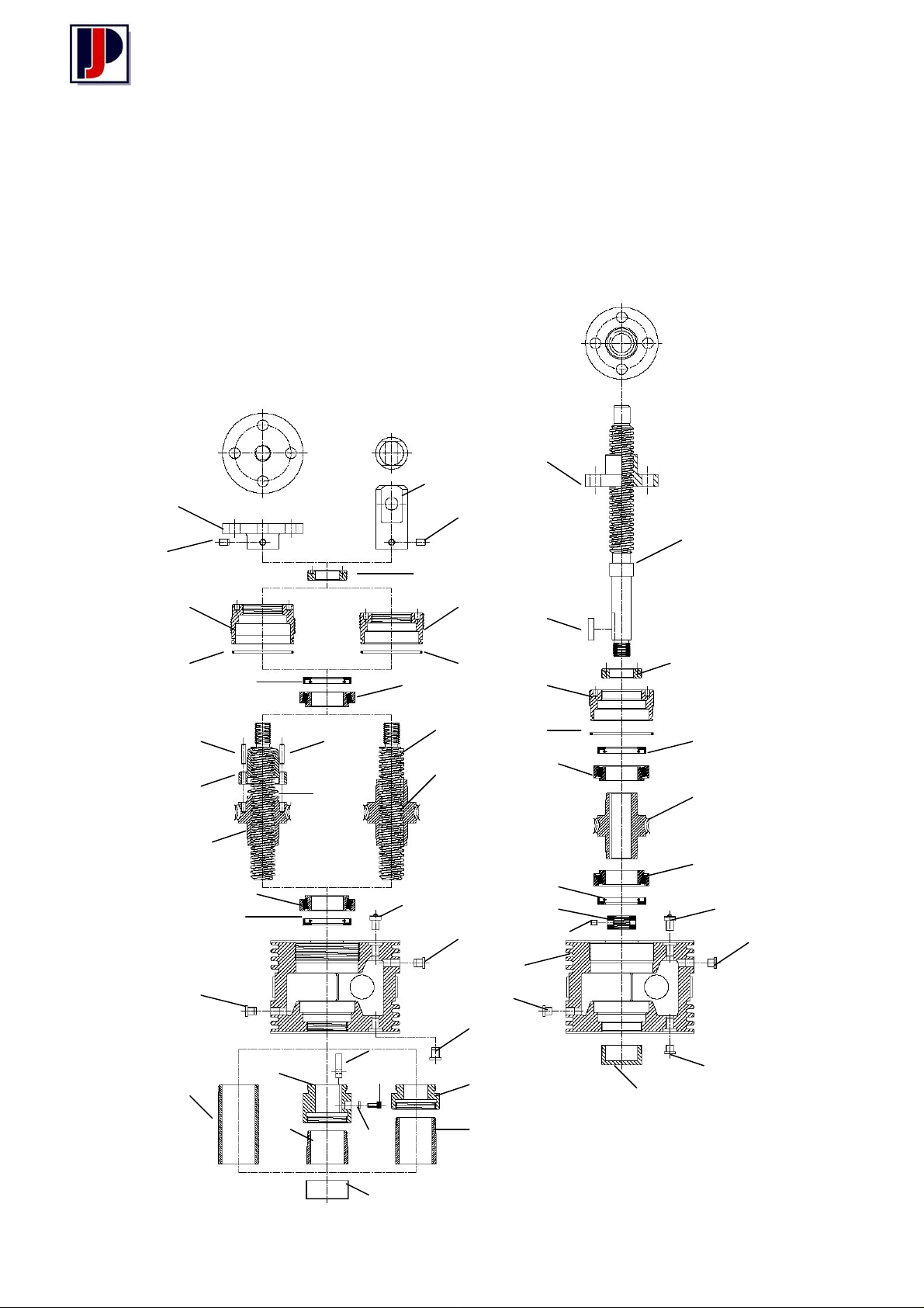
5 General Assembly & Parts List
5.1 General Arrangement – Part A
Translating Screw Rotating Screw
20
19
21
21
3
2 2
8
6
24
24
23
26
13 13
12
5
12
22
6
8
1
17
16
14
16
27
14
28
29
30
16
31
14
37
12
38
3
2
13 8
6
25
6
16
8
39
39
40
1
41
17
16
16
15
5
Page 6
Sym-metric Series – Screw Jacks
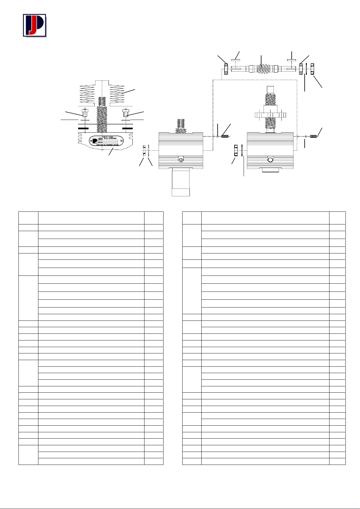
5.2 General Arrangement – Part B
33
34
34
35 35
32
9 10
7
36 18
5.3 Parts List
Item
* For anti-backlash keyed inverted screw there is no internal thread on key adaptor.
Description Qty Item
No
1 Shell 1 22 Worm Gear (6:1 Ratio-Anti-backlash) Double Start 1
2 Shell Cap 1 Worm Gear (8:1 Ratio-Anti-backlash) Double Start 1
Shell Cap Anti-backlash 1 Worm Gear (24:1 Ratio-Anti-backlash) Double Start 1
3 Guide Bushing 1 23 Anti-backlash Nut 1
4 Worm Shaft (6:1 Ratio) 1 Anti-backlash Nut (Double Start) 1
Worm Shaft (8:1 Ratio) 1 24 Dowels 4
Worm Shaft (24:1 Ratio) 1 25 Worm Gear (6:1 Ratio - Rotating) 1
5 Worm Gear (6:1 Ratio) 1 Worm Gear (8:1 Ratio – Rotating) 1
Worm Gear (8:1 Ratio) 1 Worm Gear (24:1 Ratio – Rotating) 1
Worm Gear (24:1 Ratio) 1 Worm Gear (6:1 Ratio- Rotating) Double Start 1
Worm Gear (6:1 Ratio) Double Start 1 Worm Gear (8:1 Ratio- Rotating) Double Start 1
Worm Gear (8:1 Ratio) Double Start 1 Worm Gear (24:1 Ratio- Rotating) Double Start 1
Worm Gear (24:1 Ratio) 1 26 ‘O’ Ring Anti-backlash Nut) 1
6 Load Bearing 2 27 Key Adaptor 1
7 Worm Shaft Bearing 2 Key Adaptor (Anti-backlash) * 1
8 Seal 2 28 Key (Lifting Screw) 1
9 Seal (Worm Shaft) 2 29 Cap Screw 1
10 Circlip 2 30 Lock Washer 1
11 Ke y (Worm Shaft) 2 31 Secondary Guide Bushing 1
12 Lifting Screw 1 32 Name Plate (includes fixing screws) 1
Lifting Screw (Keyed) 1 33 Bellows Boot Kit 1
Lifting Screw (Double Start) 1 includes Bellows Boot 1
Lifting Screw (Rotating) 1 End Plate 1
13 O Ring (She ll Cap) 1 End Plate Gasket 2
14 Bottom Pipe 1 34 Hex Headbolt 4
15 Bottom Pipe C ap 1 35 Washer 4
16 Plug 3 36 Locking Plug 1
17 Breather Pl ug 1 37 Lifting Nut – Single Start 1
18 Set Screw (M8 x 20mm) 1 Lifting Nut – Double Start 1
19 Clevis End 1 38 Drive Key (Lifting Screw) 1
20 Top Plate 1 39 Lock Nut (Lifting Screw 1
21 Set Screw (M8 x 12mm 4 40 Grubscrew (Lifting Screw Locknut) 1
22 Worm Gear (6:1 Ratio – Anti-backlash) 1 41 Bottom Cap 1
Worm Gear (8:1 Ratio – Anti-backlash) 1
Worm Gear (24:1 Ratio – Anti-backlash) 1
Description Qty
No
11
9
10
4
11
12
9
10
18
36
6
Page 7

Sym-metric Series – Screw Jacks
6 Disassembly / Assembly Instructions (D.A.I.)
6.1 Translating Screw D.A.I
6.1.1 Main Unit
6.1.1.1 Ensure that shell cap grub screw and plug (18) are slackened back clear of the thread grip (36) in
shell (1) before unscrewing the shell cap (It may be necessary to tap shell cap loose).
6.1.1.2 On some models it will be necessary to remove the worm shaft (4) before the worm gear assembly
can be pulled clear of the shell.
6.1.1.3 Check all parts for damage or excessive wear and replace where necessary paying special
attention to “O” rings (13) & oil seals (8 & 9).
6.1.1.4 After re-assembly of the worm shaft assembly, strike each end of worm sharply with a wooden or
fibre mallet to seat bearings properly. (Bearings must be assembled with the shield facing
outwards).
6.1.1.5 Press oil seals (9) into worm recesses in shell housing (1) with the sealing members pointing
inwards.
6.1.1.6 When re-assembling the worm gear and load bearings ensure that the bearings are fitted so that
the plate with the smallest bore size fits over the worm gear spigot.
6.1.1.7 The shell cap should be fitted after the worm shaft assembly has been securely clamped and with
the worm gear assembly in position. Tighten the shell cap until a slight drag is felt on rotating the
worm shaft by hand.
6.1.1.8 For anti-backlash actuators the shell cap must be screwed up with the lifting screw inserted and
only as tight as to allow the required backlash and lifting screw and worm gear. For normal screw
jack operation the recommended backlash is 0.05mm (0.002”).
6.1.1.9 Tighten shell cap grub screw (18). It may be necessary to fit a new thread grip if it has become
worn due to numerous adjustments.
6.1.1.10 For keyed actuators it is recommended that the lifting screw be threaded into the worm gear as far
as required before fitting the key (28).
6.1.1.11 It is important that the detachable ends are securely fixed to the lifting screws and the following
procedure should be adhered to.
6.1.2 Instructions for fitting detachable ends on lifting screws.
6.1.2.1 Thread the detachable end on to the lifting screw and tighten up as hard as possible without
damaging the components.
6.1.2.2 Select a twist drill, which is a free fit in the tapped holes of the
detachable end. Using these holes as a drill guide, drill dimple only into
the lifting screw. Clean out swarf and remove detachable end. Select
another drill which matches the set screw diameter and, using the drill
dimples as a guide, drill into the lifting screw a full diameter depth of
1mm below the root diameter of the threads. Refit detachable end.
1mm
deep
drill
holes
6.1.2.3 Fit the knurled point set screws (supplied with detachable ends) firmly in
place ensuring that point of set screws make contact with bottom of drill
dimples. Secure the set screws with Loctite.
6.1.2.4 If actuators with keyed lifting screws are involved, and it is required to line up the clevis flats or top
plate holes, etc. in a fixed relationship to the worm shaft centreline, it will be necessary to face the
underside of the detachable end to obtain the required relationship. This operation should be done
carefully as only a few hundredths of a mm (thousands of an inch) removed from the attachment is
equivalent to a fair amount of rotational movement.
7
Page 8

Sym-metric Series – Screw Jacks
6.2 Rotating Screw D.A.I.
6.2.1 Main Unit
6.2.1.1 Ensure that shell cap grub screw and plug (18) are slackened back clear of the thread grip (36) in
shell (1) before unscrewing the shell cap (It may be necessary to tap shell cap loose).
6.2.1.2 On some models it will be necessary to remove the worm shaft (4) before the worm gear assembly
can be pulled clear of the shell.
6.2.1.3 Check all parts for damage or excessive wear and replace where necessary paying special
attention to “O” rings (13) & oil seals (8 & 9).
6.2.1.4 After re-assembly of the worm shaft assembly, strike each end of worm sharply with a wooden or
fibre mallet to seat bearings properly. (Bearings must be assembled with the shield facing
outwards).
6.2.1.5 Press oil seals (9) into worm recesses in shell housing (1) with the sealing members pointing
inwards.
6.2.1.6 When re-assembling the worm gear and load bearings ensure that the bearings are fitted so that
the plate with the smallest bore size fits over the worm gear spigot.
6.2.1.7 The shell cap should be fitted after the worm shaft assembly has been securely clamped and with
the worm gear assembly in position. Tighten the shell cap until a slight drag is felt on rotating the
worm shaft by hand.
6.2.1.8 Tighten shell cap grub screw (18). It may be necessary to fit a new thread grip if it has become
worn due to numerous adjustments.
8
Page 9

Sym-metric Series – Screw Jacks
7 Warranty Information
7.1 Limitation of Responsibility
The ratings given in this manual were compiled using standard engineering procedures. The ratings are
designed to guide the customer in the selection and use of a unit. We do not guarantee the ratings in
specific applications. Prototype testing of every application is recommended before production. Our
engineering facilities are available for consultation at all times. Please ask us for assistance with linear
motion and drive application problems. This manual is designed to assist in the selection of a suitable linear
motion or power transmission product for economical. long and trouble free service.
Due to Power Jacks policy of continuous improvement designs may be subject to change without notice.
Please ask for certified drawings.
7.2 Warranty
Subject to the condition stated herein, Power Jacks will repair or replace, without charge, any parts proven
to Power Jacks satisfaction to have been defective in material or workmanship. Claims must be made
within one year after date of shipment. Power Jacks will not repair or replace any parts that have become
inoperative because of improper maintenance, eccentric loading, overloading, chemical or abrasive action,
excessive hear, or other abuse. Equipment which has been altered or modified by anyone without Power
Jacks authorisation, is not warranted by Power Jacks, EXCEPT AS STATED HEREIN, POWER JACKS
MAKES NO OTHER WARRANTIES, EXPRESS OR IMPLIED INCLUDING WARRANTIES OF
MERCHANTABILITY AND FITNESS FOR A PARTICULAR PURPOSE.
WARNING: The equipment shown in this manual is intended for industrial use only and should not be used
to lift support, or otherwise transport people unless you have a written statement from Power Jacks Limited
which authorises the specific unit as used in your application suitable for moving people.
© Power Jacks Limited 1987, Aberdeenshire, Scotland, United Kingdom.
We reserve the right to alter details and specifications without notice.
Since special circumstances may affect the equipment’s operation, users should consult POWER
JACKS LIMITED at the address shown, or take other skilled engineering advice.
It is recommended that the application design load is conspicuously displayed.
© POWER JACKS LIMITED. May not be copied in whole or in part
POWER JACKS GROUP LIMITED
SOUTH HARBOUR ROAD, FRASERBURGH,
ABERDEENSHIRE, AB43 9BZ SCOTLAND
TELEPHONE: +44 (0) 1346 513131 FAX: +44 (0) 1346 516827
email: [email protected] http://www.powerjacks.com
9
 Loading...