

Page 1

IMPERIAL MACHINE SCREW JACKS
SINGLE FACE MOUNTING
(MECHANICAL LINEAR ACTUATORS)
SPARES LIST &
MAINTENANCE
INSTRUCTIONS
MANUAL : MM-IMS-E-02
SUPPLIED BY: POWER JACKS LIMITED
Page 2
Imperial Series – Machine Screw Jacks
CONTENTS
1 UNIT DETAILS ....................................................................................................................................................................... 2
2 GENERAL INFORMATION ................................................................................................................................................. 3
2.1 G
ENERAL ................................................................................................................................................................................ 3
2.2 I
NDUSTRIAL USE ONLY ........................................................................................................................................................... 3
2.3 TABLE OF SPECIFICATIONS ...................................................................................................................................................... 3
2.4 IMPORTANT PRECAUTIONS ...................................................................................................................................................... 4
3 MAINTENANCE ..................................................................................................................................................................... 5
3.1 L
UBRICATION ......................................................................................................................................................................... 5
3.2 R
EBUILD PROCEDURE ............................................................................................................................................................. 5
3.3 R
EQUIRED TOOLS ................................................................................................................................................................... 5
3.4 DISASSEMBLY (REFER TO FIGURE 3-1) ................................................................................................................................... 5
3.5 C
LEANING .............................................................................................................................................................................. 6
3.6 I
NSPECTION (REFER TO FIGURE 3-1) ....................................................................................................................................... 6
3.7 ASSEMBLY (REFER TO FIGURE 3-1) ....................................................................................................................................... 6
3.8 A
NTI-BACKLASH NUT FUNCTION ........................................................................................................................................... 7
3.9 A
NTI-BACKLASH NUT ADJUSTMENT ...................................................................................................................................... 7
4 PARTS LIST ............................................................................................................................................................................ 8
4.1 G
ENERAL ................................................................................................................................................................................ 8
4.2 PARTS LIST FOR 1800, 9000 & 9400 SERIES MACHINE SCREW JACKS .................................................................................... 8
4.3 ASSEMBLY DRAWING ............................................................................................................................................................. 9
5 WARRANTY INFORMATION ........................................................................................................................................... 10
5.1 L
IMITATION OF RESPONSIBILITY .......................................................................................................................................... 10
5.2 WARRANTY .......................................................................................................................................................................... 10
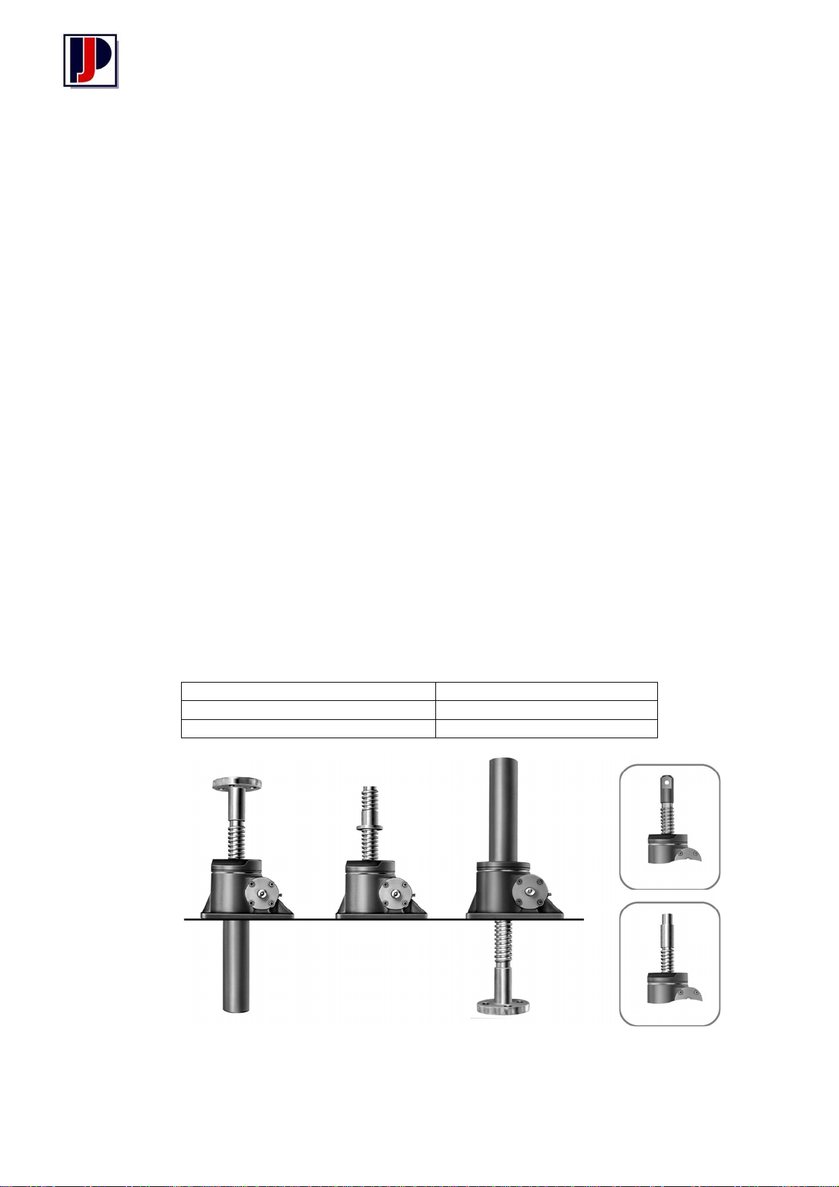
1 Unit Details
Serial Number
Model Number
Power Jacks Sales Order Number
Clevis
Upright Screw
Rotating Screw (Upright)
Available in both upright
& inverted types
2
Threaded
Inverted Screw
Page 3
Imperial Series – Machine Screw Jacks
¾
¼
2 General Information
2.1 General
This manual contains maintenance instructions for Power jacks 1800, 9000, 4800 and 9800 imperial
machine screw jacks. It describes and details procedures for disassembly, cleaning, inspection, rebuilding
and assembly of these screw jacks.
2.2 Industrial use only
The ball screw jacks described and illustrated in this manual are intended for industrial use only and should
not be used to lift, support, or otherwise transport people unless you have a written statement from Power
Jacks, which authorises the specific screw jack, as used in your application, as suitable for moving people.
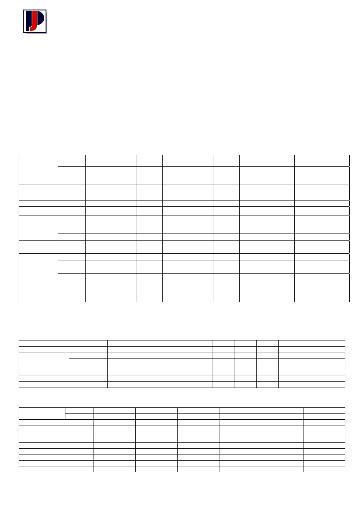
2.3 Table of specifications
Model
Number
Rated Load (Tons)
Diameter of Lifting Screw
(ins)
Closed Height ** (in)
Base Size (in)
Worm Gear
Ratios
Turns of worm
for 1” raise
Maximum HP
per actuator
Torque at Full
Load* (in.lb)
Jack efficiency
Rating (%)
Weight with Base
Raise of 6” (lbs)
Weight for each
additional 1” Raise (lbs)
Upright
Inverted
Std. Ratio
Optional
Std. Ratio
Optional
Std. Ratio
Optional
Std. Ratio
Optional
Std. Ratio
Optional
* For loads of from 25% to 100% of jack load rating. Torque requirements are approximately proportional to the load.
** Closed heights are for standard upright models and may vary with different screw ends, inverted models, or when bello ws
boot is used
TABLE 2. 4800 AND 9400 SERIES
Actuator No 4802 & 9402 4805 4810 4815 4820 4825 9435 4850 4899 48150
Rated load (tons) 2 5 10 15 20 25 35 50 100 150
Torque at full load
(in-lbs)
Jack efficiency rating % 19.6
Closed Height (in) 5¼ 7 7¼ 8 9¼ 12 13 14 26½ 26¼
Weight with Base raise of 6” (lb) 18 37 55 70 101 197 250 440 1325 1475
NOTE: Additional specifications are same as for Series 1800 and 9000. See Table 1.
Model Number
Rated Load (tons) 2 5 10 15 20 25
Lifting Screw 1” dia
Worm Gear Ratio 25:1 25:1 25:1 25:1 25:1 25:1
Turns of Worm for 1” Raise 100 100 100 100 100 100
Torque at Full Load (in-lbs) 48 175 270 640 925 1500
Actuator efficiency Rating % 13.2 9.1 8.6 7.5 6.9 5.3
Maximum H.P per Screw Jack ½ ¾ 1½ 1½ 1½ 2½
Note: All other data for these models same as shown in Table 1
Upright 1802 & 9002 9005 9010 9015 9020 9025
Inverted 1801 & 9001 9004 9009 9014 9019 9024
1802 &
9002
1801 &
9001
1805 1810 1815 1820 1825 9035 1850 1899 18150
1804 1809 1814 1819 1824 9034 1849 1898 8149
2 5 10 15 20 25 35 50 100 150
1
.20 Pitch
Acme
5¼ 7 7¼ 8 9¼ 11 12 13 24 24
3½ x 7
4½ x 6¼
6:1 6:1 8:1 8:1 8:1 10 2/3:1 10 2/3:1 10 2/3:1 12:1 12:1
24:1 24 24:1 24:1 24:1 10 2/3:1 10 2/3:1 10 2/3:1 36:1 36:1
24 16 16 16 16 16
96 64 48 48 48 48
1½
.375 Pitch
Square
6 x 8 7½ x 8
2
.500 Pitch
Square
2¼
.500 Pitch
Square
7¾ x 9
2½
.500 Pitch
Square
8¼ x 11 10¼x13 ¾ 10¼ x 15 ½ 9¾ x 19¾ 20¾ x 27½ 20¾ x 24½
3⅜
.666 Pitch
Square
3¾
.666 Pitch
Square
16
48
4½
.666 Pitch
Square
6
.750 Pitch
Square
7
.1 Pitch
Square
16 16 12
48 48 36
2 4 5 5 5 8 8 15 25 25
½ 1½ 1½ 1½ 2½ 2½ 6 11 11
120 450 950 1,430 2,050 3,360 4,600 7,500 16,000 28,100
50 185 490 820 1,170 1,900 2,750 4,200 8,600 15,500
23.2 22.1 22.0 20.2 18.2 16.4 15.2 13.8 13.0 14.1
13.3 12.1 14.0 12.9 20.2 9.2 8.5 8.3 8.0 8.6
17 35 52 66 93 181 240 410 1,200 1,350
.33 .85 1.4 1.5 2.6 3.5 4.1 5.5 9.0 12.6
Std Ratio 135 500 1005 1658 2261 3712 5060 8022 17004 31330
Optional 56 228 526 904 1228 1947 3025 4542 9210 17225
11.9
.250 Pitch
Acme
19.9
10.9
1½” dia
.250 Pitch
Acme
19.8
12.6
18.0
11.7
2” dia
.250 Pitch
Acme
16.9
10.8
14.8
8.3
2¼” dia
.250 Pitch
Acme
13.7
7.7
12.4
7.3
2½” dia
.250 Pitch
Acme
11.7
7.2
12.7
7.7
3⅜” dia
.250 Pitch
Acme
3
Page 4

Imperial Series – Machine Screw Jacks
2.4 Important precautions
In order to ensure that Power Jacks machine screw jacks provide good service over a period of years the
following precautions should be taken:
1. Select a screw jack that has a rated capacity greater than the maximum load that may be imposed on it.
2. The structure on which the jacks are mounted should have ample strength to carry the maximum load,
and should be rigid enough to prevent undue deflection or distortion of the jacks supporting members.
3. It is essential that the screw jacks be carefully aligned during installation so that the lifting screws are
perfectly plumb and the connecting shafts are exactly in line with the worm shafts. After the jacks,
shafting, gear boxes etc., are coupled together, it should be possible to turn the main drive shaft by
hand. If there are no signs of binding or misalignment, the jacking system is then ready for normal
operation.
4. The machine screw jacks should have a greater raise than is needed in the actual installation. Should it
be necessary to operate the jacks at the extreme limits of travel, it should be done cautiously.
Caution: Do not allow screw jack to go beyond specified (catalog) closed height of
actuator or serious damage to internal jack mechanism may result. Refer to
table of specifications (par 1-3) for closed height of respective units.
5. The worm shaft speed for these jacks should not exceed 500 RPM for light loads of one-fourth (or
less) of the jack load rating.
6. The lifting screw should not be permitted to accumulate dust and grit on the threads. If possible, lifting
screws should be returned to closed position when not in use.
Caution: Where lifting screws are not protected from airborne dirt, dust, etc., bellows
boots should be used. Inspect frequently at regular intervals to be certain that
a lubricating film is present. Lifting screws should never be run dry.
7. When using an 1800 or 9000 Series screw jacks periodic check of backlash of the lifting screw thread
is recommended to check wear of the worm gear internal threads. The normal backlash on a new unit
of this type is approximately .010 inch. Backlash of 50% or more of the thread thickness indicates
the need to replace the worm gear. The 4800 and 9400 Series anti-backlash jacks are designed to
be adjusted for minimum backlash, approximately .002 inch. The worm gear and anti-backlash nut
faces of ½ the thread thickness. When adjustments have been made to the point where all this
clearance is gone, 50% of the thread thickness is gone and replacement is necessary. (Refer
Section 3.8 for a detailed explanation of how the anti-backlash nut functions).
Note: For loads from 25% to 100% of screw jack capacity, torque requirements are
approximately proportioned to the load, except for very light loads.
8. The lubrication procedures for normal and severe service conditions, (refer Section 3.1) should be
closely followed.
4
Page 5

Imperial Series – Machine Screw Jacks
3 Maintenance
3.1 Lubrication
Unless otherwise specified, screw jacks are shipped packed with grease which should be sufficient for one
month of normal operation. For normal operation the screw jack and gear boxes should be lubricated once
a month, using one of the following Extreme Pressure greases or their equivalent.
Socony Mobile Oil Co Mobilplex E.P. #1
Texaco Texaco E.P. #1
Gulf Oil Corp Gulf Crown E.P #1
Shell Oil Co Shell Alvania E.P #1
For severe service conditions, the jacks should be lubricated more frequently using one of the above
greases (daily to weekly depending on conditions). If duty is heavy, an automatic lubrication system is
strongly recommended. If ambient temperatures exceed 200°F, consult lubricant manufacturers.
Caution: Where lifting screws are not protected from airborne dirt, dust, etc., bellows
boots should be used. Inspect frequently at regular intervals to be certain that
a lubricating film is present. Lifting screws should never be run dry.
3.2 Rebuild Procedure
Power Jacks recommend the following procedures for assembly and disassembly of machine screw jacks.
1. Tag critical parts to facilitate re-assembly.
2. Mark mating surfaces to insure proper meshing.
3. Clean and lubricate all parts as required.
4. All seals must be replaced when rebuilding.
5. All screws, washers and other small common parts must be replaced if damaged in any way.
6. Replace damaged or frozen lubrication fittings with new ones.
3.3 Required Tools
A bearing puller and press, and common hand tools are necessary for proper assembly and disassembly.
3.4 Disassembly
(Refer to Section 4.3)
1. Remove lifting screw (5) from jack.
2. Remove bottom pipe (4) from shell (3) (upright models) or shell cap (2) (inverted models) or base plate
as applicable.
3. FOR ALL MODELS EXCEPT 100 & 150 TON –
Loosen and remove set screws (1) in cap (2) and remove cap from shell (3)
FOR 100 & 150-TON MODELS –
Loosen the lock screw in the shell and unscrew (Counterclockwise) the base plate from the shell.
Note: It may be necessary to break shell cap or base plate loose with a hammer.
4. Remove gear (6A) or worm gear and nut assembly (6B) from shell (3)
Note: To facilitate removal of the gear from the shell on models with 50-ton or higher load
ratings, partially reassemble the lifting screw into the worm gear (or worm gear and
nut assembly) and use a hoist or pulley block to lift on the screw.
5
Page 6

Imperial Series – Machine Screw Jacks
5. Remove the top load bearing (7) which may be attached to either the shell cap (2) or worm gear (6A) or
anti-backlash nut.
Caution: Use only a wooden mallet to tap bearings loose.
6. Remove bottom load bearing (8) which may be attached to either the shell (3) (base plate for 100 and
150-ton models) or worm gear (6A).
7. Remove four cap screws (9) from each of the two worm flanges (11) and remove flanges.
8. Press oil seal (13) out of flange (11).
9. Remove worm (14 and worm bearings (15) from shell (3) by striking one end of wooden or lead mallet.
10. Remove worm bearings (15) from worm (14) with bearing puller or press. (NOTE: this step will not be
necessary if worm and worm bearings are not damaged.)
11. If screw jack is keyed, remove screw in shell cap (shell on 100 and 150-ton models) and tap key out of
keyway.
3.5 Cleaning
1. Use degreasing solvent, to remove grease or oil from all parts.
Caution: Remove grease from unit and do not reuse old grease.
Warning: Provide adequate ventilation during the use of cleaning agents; avoid
prolonged breathing of fumes and contact with skin.
2. Use clean water or soap solution for general cleaning of painted surfaces.
3. Dry parts thoroughly after cleaning
Note: Before installing new parts, remove any rust preventive protection grease etc.
3.6 Inspection
(Refer to Section 4.3)
1. Make a visual inspection of shell (3) for broken, cracked or distorted areas. Check threads of all bores
for burrs or broken threads.
2. Check shell cap (2), base plate, bottom pipe (4), lifting screw (5), worm gear (6A) or worm gear and nut
assembly (6B) for burrs or scratches on their working or mating surfaces.
3. Check fit between lifting screw thread and internal thread in worm gear. If fit is excessively loose,
replace worm gear or lifting screw as required. Replace worm gear and nut assembly as a set (4800 &
9400 Series).
4. Check small common components (screws, etc.) and replace as required.
5. Check bearings (7, (8) and (15) for seizure, galling or play and replace as required.
3.7 Assembly
(Refer to Section 4-3)
1. Press worm bearings (15) onto worm shaft (14) making sure that bearings are seated properly against
shoulder.
Note: When tapered roller bearings are used, the small end of the cone should point to the worm
end.
2. Position worm shaft end (14) in shell (3).
Note: If tapered roller bearings are used, tap worm bearing cups into place in the shell.
3. Press oil seals (13) into worm flange (11).
Note: The sealing element should point inward
4. Position worm flanges (11) with shims (12) and bolt in place.
5. Position bottom load bearing (8) (bearing cup on 5-ton and 35-ton models, top load bearing on 100 and
150-ton models) in shell (3).
6
Page 7

Imperial Series – Machine Screw Jacks
5a On 5-ton and 35-ton models, press load bearing cones onto worm gear (6A) or worm gear nut
assembly (6B). Small end of bearing cone should face away from gear teeth.
6. Install worm gear (6A) or worm gear and nut assembly (6B) in shell (3).
Caution: Strike each end of worm shaft sharply with a wooden mallet to seat bearing
properly. Recheck flange bolts for tightness. Worm should turn freely with
minimum drag and end play. if too much end play is present, remove shims as
required. If worm does not turn freely, add shims as required.
7. Install top load bearing (7) (bottom load bearing (8) for 100 and 150-ton models on worm gear (6A) or
worm gear and nut assembly (6B).
8. Fill housing fully with grease.
9. FOR ALL MODELS EXCEPT 100 AND 150-TON – Install shell cap (2) and screw down until tight.
Note: Shell cap flange does not necessarily have to bear against top shell, there will usually be a
gap. This will put a slight drag on worm. If worm is hard to turn, back off slightly on shell cap.
FOR 100 AND 150-TON MODELS – Install base plate and screw down base plate until tight.
Note: This should put a slight drag on the worm. If the worm is hard to turn, back off slightly on the
base plate. Be sure base plate does not project past base surface of housing.
10. Lock shell cap in place with set screws (lock screw on 100 and 150-ton models)
11. FOR ALL MODELS EXCEPT 100 AND 150-TON – Screw bottom pipe (4) into shell (3) (upright
models) or into shell cap (2) (inverted models)
FOR 100 AND 150-TON MODELS – Screw bottom pipe into base plate (upright models) or into shell
(inverted models)
12. Brush lifting screw (5) with a light film of grease and install in actuator. On inverted models, install guide
bushing (16) and then install lifting screw (5).
13. If screw jack is keyed, install key in shell cap (2) (shell for 100 and 150-ton models) and bolt in place.
14. Operate unit to ensure proper functioning of all components prior to reinstallation.
3.8 Anti-Backlash Nut Function
As shown in Figure 3-1, the worm gear (2) and anti-backlash nut (3) are printed together with guide pins.
The threads in the anti-backlash nut work in opposition to the threads in the worm gear as they engage the
threads of the lifting screw (1). Adjustment of backlash is made by running down on the shell cap of the
screw jack. This forces the anti-backlash nut threads into closer contact, reducing clearance and thus
reducing backlash.
3.9 Anti-Backlash Nut Adjustment
1. To minimise backlash remove the two set screws
(4) and tighten down on shell cap until the desired
backlash is obtained. Spot drill top of shell through
set screw holes, then replace set screws and tighten
to prevent shell cap backing off.
2. To avoid binding and excessive wear, do not adjust
lifting screw backlash to less than 0.002 inch.
3. The clearance (A) designed into the worm gear and
anti-backlash nut is set one-half the thread thickness.
When adjustments have been made to use all this
clearance replace the worm gear and anti-backlash
nut as a set.
Figure 3-1 Anti-backlash Nut Adjustment
7
Page 8
Imperial Series – Machine Screw Jacks
4 Parts List
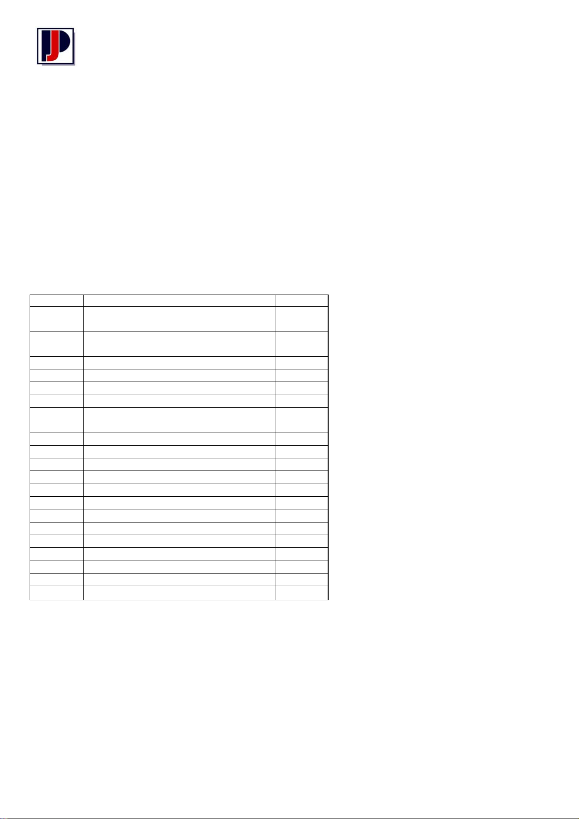
4.1 General
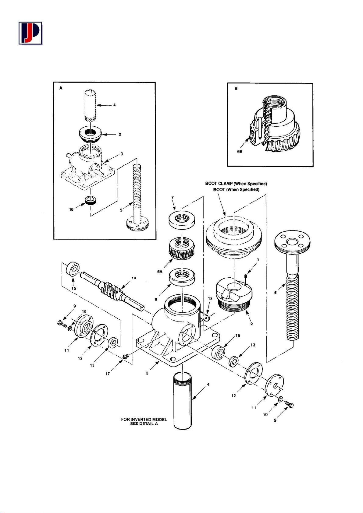
This section contains an exploded illustration of the M1800, M9000, M4800 and M9400 Series machine
screw jack. The number adjacent to each part on the illustration is the index number. Keyed to this index
number on the parts list is the part name
When ordering parts be sure to include:
1. The nameplate model of your unit
2. Index number and name of part
4.2 Parts List for M1800, M9000, M4800 & M9400 Series Machine Screw Jacks
Index No Part Name Qty Req
1 Screw, Set
(All models except 100 & 150-ton)
2 Cap Shell
(All models except 100 & 150-ton)
3 Shell, Jack 1
4 Pipe, Bottom 1
5 Screw Assembly, Lifting 1
6A Worm Gear 1
6B Worm Gear & Anti-backlash Nut
Assembly Mfg’d & sold in sets only)
7 Bearing, Top Load 1
8 Bearing, Bottom Load 1
9 Screw, Cap 8
10 Washer, Lock 8
11 Flange, Worm 2
12 Shim, Flange 2
13 Seal, Oil 2
14 Worm 1
15 Bearing, Worm 2
16 Bushing, Guide (inverted model only) 1
18 Name plate 1
19 Screw, Lock (100 & 150-ton only) 1*
20 Plate, Base (100 & 150-ton only)
* Not shown
2
1
1
1*
8
Page 9
Imperial Series – Machine Screw Jacks
4.3 Assembly Drawing
Exploded Illustration M1800, M9000, M4800 & M9400 Series Machine Screw Jacks
9
Page 10

Imperial Series – Machine Screw Jacks
5 Warranty Information
5.1 Limitation of Responsibility
The ratings given in this manual were compiled using standard engineering procedures. The ratings are
designed to guide the customer in the selection of a unit. We do not guarantee the ratings in specific
applications. Prototype testing of every application is recommended before production. Our engineering
facilities are available for consultation at all times. Please ask us for assistance with linear motion and drive
application problems. This manual is designed to assist in the selection of a suitable linear motion or power
transmission product for economical. long and trouble free service.
Due to Power Jacks policy of continuous improvement designs may be subject to change without notice.
Please ask for certified drawings.
5.2 Warranty
Subject to the condition stated herein, Power Jacks will repair or replace, without charge, any parts proven
to Power Jacks satisfaction to have been defective in material or workmanship. Claims must be made
within one year after date of shipment. Power Jacks will not repair or replace any parts that have become
inoperative because of improper maintenance, eccentric loading, overloading, chemical or abrasive action,
excessive heat, or other abuse. Equipment which has been altered or modified by anyone without Power
Jacks authorisation, is not warranted by Power Jacks. EXCEPT AS STATED HEREIN, POWER JACKS
MAKES NO OTHER WARRANTIES, EXPRESS OR IMPLIED INCLUDING WARRANTIES OF
MERCHANTABILITY AND FITNESS FOR A PARTICULAR PURPOSE.
WARNING: The equipment shown in this manual is intended for industrial use only and should not be used
to lift support, or otherwise transport people unless you have a written statement from Power Jacks Limited
which authorises the specific unit as used in your application suitable for moving people.
© Power Jacks Limited 1987, Aberdeenshire, Scotland, United Kingdom.
We reserve the right to alter details and specifications without notice.
Since special circumstances may affect the equipment’s operation, users should consult POWER
JACKS LIMITED at the address shown, or take other skilled engineering advice.
It is recommended that the application design load is conspicuously displayed.
© POWER JACKS LIMITED. May not be copied in whole or in part
POWER JACKS LIMITED
SOUTH HARBOUR ROAD, FRASERBURGH,
ABERDEENSHIRE, AB43 9BZ SCOTLAND
TELEPHONE: +44 (0) 1346 513131 FAX: +44 (0) 1346 516827
email: [email protected] http://www.powerjacks.com
10
 Loading...