

Page 1
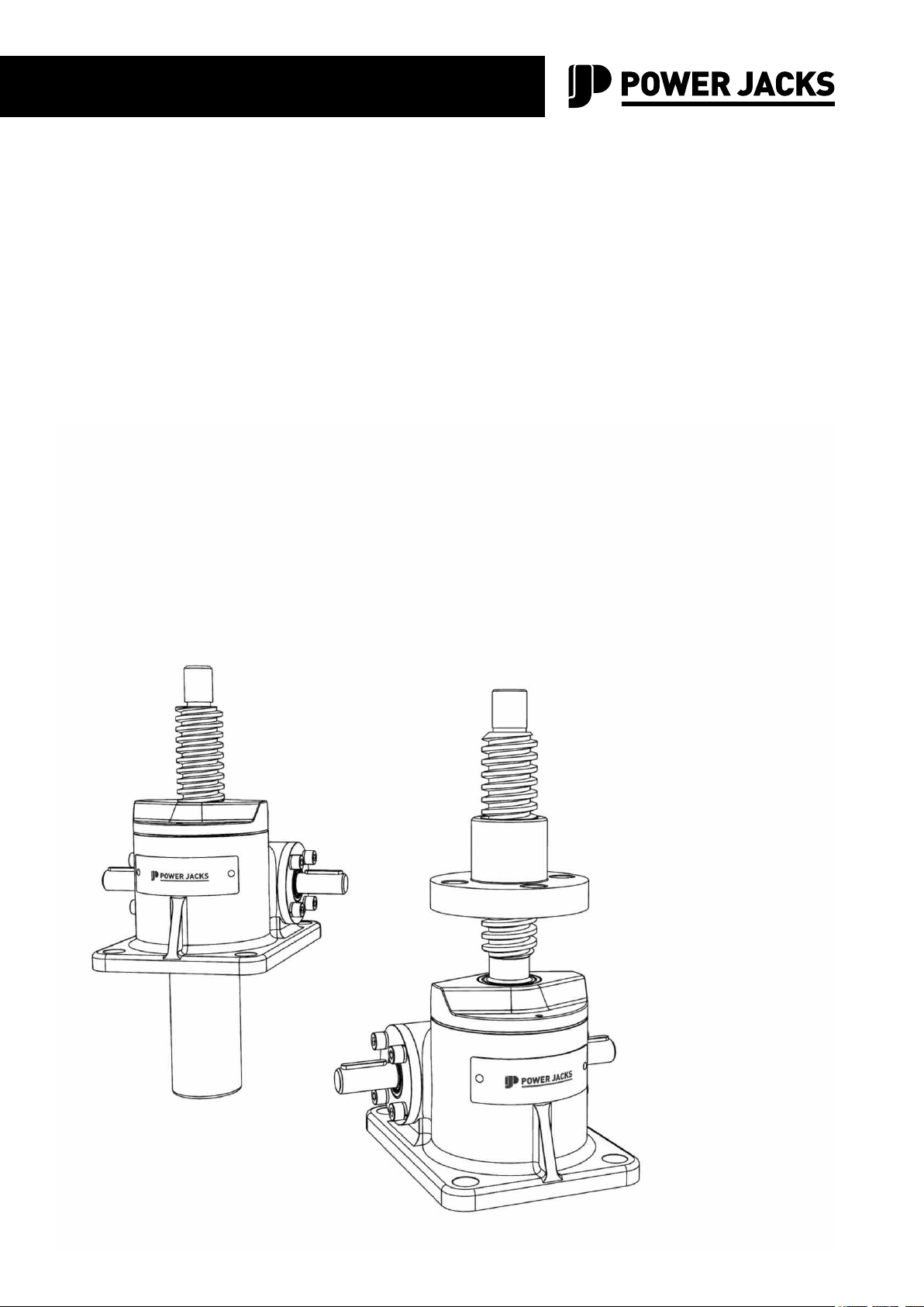
MAINTENANCE MANUAL
E-Series
Machine Screw Jack
MM-SJ-EMS-EN-01
Operation & Maintenance Instructions with Parts List
Page 2

Page 3

Contents
E-SERIES
MACHINE SCREW JACKS
SPARES LIST & MANUAL
MM-SJEMS-EN-01
1. Introduction .......................................................................................................................................................... 4
2. Product Code ........................................................................................................................................................ 8
3. Standard Performance ......................................................................................................................................... 9
4. Installation .......................................................................................................................................................... 10
5. Operation ............................................................................................................................................................ 15
6. Maintenance ....................................................................................................................................................... 21
7. Recommended Lubricants ................................................................................................................................. 26
8. Spare Parts ......................................................................................................................................................... 27
9. Storage & Warehousing ..................................................................................................................................... 28
10. Disposal of Units ................................................................................................................................................ 29
11. Warranty ............................................................................................................................................................. 30
12. General Assembly & Parts List .......................................................................................................................... 31
www.powerjacks.com 3
Page 4
1
Introduction
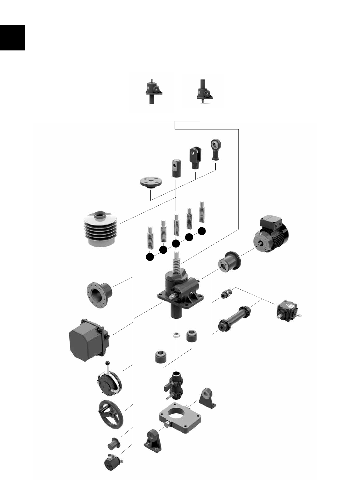
1.1 TranslatingCongurations
Upright Inverted
Fork End
Clevis End
Top Plate
Available as:
1. Standard
2. Anti-Backlah
3. Anti-Rotation (Keyed)
4. Safety Nut
Rod End
Lead Screw Options:
1. Standard 1 x Pitch
2. 2 x Pitch
3. Anti-Rotation (Keyed)
4. Stainless Steel
5. Left Hand Thread
Rotary Limit
Switch Adaptor
Rotary Limit Switch
Bellows Boot
Brake
1
Stop Nut
Secondary
Guide
5
4
3
2
Electric Motor with or without:
• Brake
• Encoder
Motor Adaptor
Coupling
Drive Shaft
Anti-Rotation
Key Adaptor*
Limit Switches
• Forced Ventilation
Gearbox
Hand Wheel
Protection Cap
Encoder
4 www.powerjacks.com
Trunnion Feet
Trunnion
* For use with Anti-Backlash and some safety nut models only.
Page 5
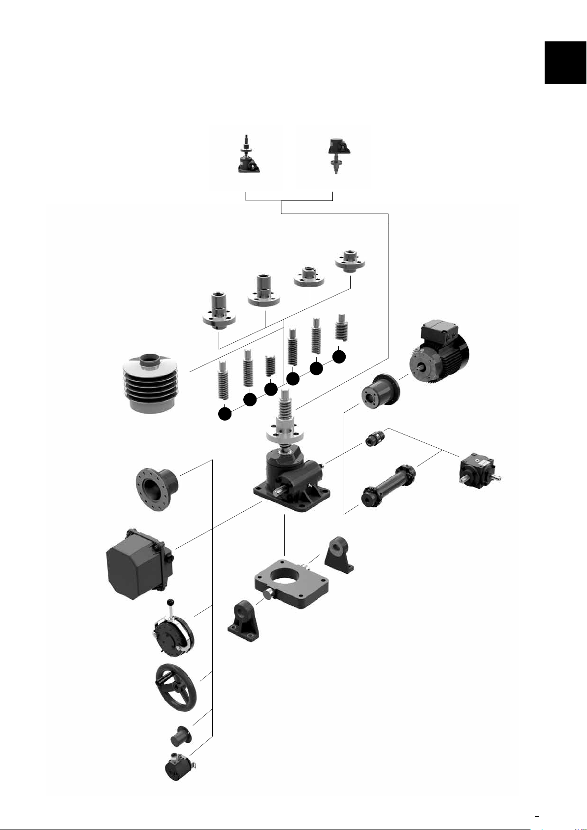
1.2 RotatingCongurations
Upright Inverted
Safty Nut
Double Hub
Safety Nut
Standard
Nut
Double Hub
Nut
Introduction
Lead Screw Options:
1. Standard 1 x Pitch
2. 2 x Pitch
3. No Pilot End
4. Stainless Steel
5. Left Hand Thread
6. Larger Diameter Screw
1
Rotary Limit
Switch Adaptor
Rotary Limit Switch
Bellows Boot
6
5
4
3
2
1
Trunnion
Motor Adaptor
Coupling
Drive Shaft
Trunnion Feet
Electric Motor with or without:
• Brake
• Encoder
• Forced Ventilation
Gearbox
Brake
Hand Wheel
Protection Cap
Encoder
www.powerjacks.com 5
Page 6
1
Introduction
1.3 Introduction
E-Series screw jacks are exclusively designed for carrying out linear motion movements in accordance with the
specication detailed in Power Jacks product information and this maintenance manual.
Any other application other than specied or one going beyond the above mentioned capacity is unauthorised. The
manufacturer is not liable for damages resulting from such applications. The user alone has to bear the risk.
Since the screw jacks can be applied in various areas, the user is responsible for the specic application of use.
The E-Series machine screw jacks have been designed to comply with Machinery Directive 2006/42/EC and with
the relevant essential health and safety requirements as applies to the equipment itself. Where tted, Electric
Motors conform with Low Voltage Directive 2006/95/EC and EMC Directive 2004/108/EC.
1.4 Safety Instructions in The Operating Manual
This symbol indicates potential dangers to people.
Comply with the instructions in order to avoid injury.
This symbol indicates potential dangers to the unit.
Comply with the instructions in order to avoid damage to the unit.
This symbol indicates special information on:
• The best possible use of the unit
• How to facilitate operation of the unit
1.5 Residual Risk and Hazards
1.5.1 Should a risk of damage to material or injury to persons remain despite the structural safety of
the E-Series screw jack(s), the user must draw attention to such hazards by means of suitable
warning notices and written instructions indicating safety precautions.
6 www.powerjacks.com
Page 7

Introduction
1.6 Operating Personnel
1.6.1 The E-Series screw jacks are designed according to state-of-the-art technology and are in line
with applicable safety regulations. However, the general risks of personal injury or damage to
property connected with the use of such machinery cannot be completely eliminated. Therefore
the units may only be assembled and operated by competent and qualied personnel and only
be used for the authorised application.
1.6.2 Therefore a careful study of this operating manual should be made before attempting to use or
service the unit and particular attention should be paid to the safety instructions.
1.6.3 Work to be performed on electrical parts, such as:
• Installation of limit switches
• Mounting of the drive
• Check of the direction of rotation
should only be carried out by qualied electricians.
1.6.4 The E-Series screw jacks and the installation should be inspected by the operating and
supervising personnel for externally visible damage and defects at least once every shift. Any
changes (including the operational conditions) which may affect the safety are to be reported
immediately.
1
www.powerjacks.com 7
Page 8
2
Product Code
2.0 Example
KME1819-300-BR, 200 kN inverted keyed translating machine screw jack with top plate, 300 mm of stroke, bel-
lows boots tted to protect lifting screw and a single ended worm shaft extension on the right-hand side only.
K ME 1819 300 BR
↓ ↓ ↓ ↓ ↓
(a) (b) (c) (d) (e)
↓ ↓ ↓ ↓ ↓
Prex Basic Model Series No. Travel of Unit (mm) Sufx
Prexes (a)
S - All Stainless Steel Screw Jack.
K - Keyed Lifting Screw
Basic Model (b)
TE - Threaded end on lifting screw (standard)
ME - Top Plate on end of lifting screw.
CE - Clevis End on lifting screw.
PE - Plain end, with no machining on end of lifting
screw.
DE - Inverted rotating screw jack.
UE - Upright rotating screw jack.
CCE - Screw Jack with double clevis mounting
arrangement.
Note
1. For E-Series Screw Jacks with plain ended lifting
screws consult Power Jacks.
2. For Stainless Steel Screw Jacks with varying mate-
rials and/or platings consult Power Jacks.
3. For external keyed guides consult Power Jacks.
Capacity and Series Designations (c)
Upright Translating Screw Jacks
Third Space Numerals (d)
The characters appearing in this space are to indicate
stroke in millimetres on all standard units, but not on
specials. This space on special
actuators helps to identify to our Engineering Department the actual Screw Jack model produced. The
numerals do not indicate stroke or type of modication
performed on special orders.
Sufx (e)
B - Indicates bellows boot required to protect lift-
ing screw.
G - Secondary guide for the lifting screw.
L - Single-end worm shaft extension on left-hand
side only.
R - Single-end worm shaft extension on right-
hand side only.
1 - Gear ratio option-2 required.
X - Supplied without bottom pipe, but with guide
bushing.
Note 1. All sufxes (e) that do not conict with another
may be used in series against one Screw Jack.
E2625 E2501 E1802 E1805 E1810 E1820 E1830 E1850 E18100
5 10 25 50 100 200 300 500 1000
Inverted Translating Screw Jacks
Decrease the upright model number by 1, e.g. 1804, 50 kN inverted Screw Jack.
Rotating Screw Jacks
Increase the upright model number by 1, e.g. 1806, 50 kN rotating Screw Jack.
Anti-Backlash Screw Jacks
Replace the rst digit in the model number with a 4, e.g. 4805, 50 kN anti-backlash Screw Jack.
8 www.powerjacks.com
Page 9
Standard Performance
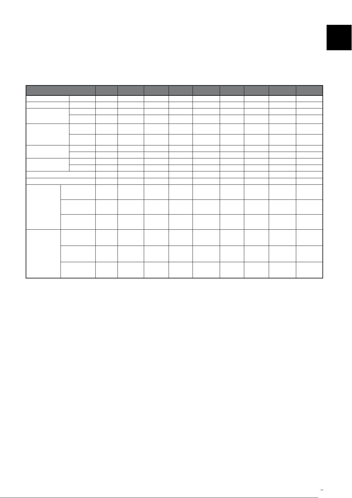
Model E2625 E2501 E1802 E1805 E1810 E1820 E1830 E1850 E18100
Capacity kN 5 10 25 50 100 200 300 500 1000
Lifting Screw
Turn of worm for travel
of lifting screw
Max. Input power (kW)
Start up torque at full
load (Nm)
Weight (kg) - stroke = 150mm 1.03 2.27 8.17 15.88 24.72 45 86 195 553
NOTE 1
Gear ratios
NOTE 2
Weight (kg) per extra 25mm 0.073 0.13 0.21 0.32 0.57 0.86 1.58 2.49 4.31
mm 16 x 3 20 x 5 30 x 6 40 x 9 55 x 12 65 x 12 95 x 16 120 x 16 160 x 20
Option 1 5:1 5:1 6:1 6:1 8:1 8:1 102/3:1 102/3:1 12:1
Option 2 20:1 20:1 24:1 24:1 24:1 24:1 32:1 32:1 36:1
Option 1 5 for 3mm 1 for 1mm 1 for 1mm
Option 2
Option 1 0.25 0.375 1.5 3 3.75 3.75 6 11.25 18.5
Option 2 0.12 0.19 0.375 0.55 1.125 1.125 1.9 4.5 8.25
Option 1 2.5 6.8 19.8 56 115.9 263.8 480 904 2025
Option 2 1.1 3 8.7 25.5 60.5 137 284 504 1119
Gear Ratio 5 5 6 6 8 8 10 2/3 10 2/3 12
20 for
3mm
4 for 1mm 4 for 1mm
1 for
1.5mm
4 for
1.5mm
1 for 1.5mm 1 for 1.5mm 1 for 1.5mm 1 for 1.5mm 3 for 5mm
2 for 1mm 2 for 1mm 2 for 1mm 2 for 1mm 9 for 5mm
3
Option 1
Option 2
Screw Jack Static
Efciency
Screw Jack
Dynamic Efciency
Gear Ratio 20 20 24 24 24 24 32 32 36
Screw Jack Static
Efciency
Screw Jack
Dynamic Efciency
0.189 0.233 0.201 0.213 0.206 0.181 0.149 0.132 0.131
0.252 0.306 0.264 0.281 0.272 0.242 0.205 0.181 0.178
0.107 0.130 0.115 0.117 0.132 0.116 0.084 0.079 0.079
0.160 0.194 0.167 0.172 0.190 0.169 0.128 0.120 0.123
Notes:
1. All metric machine screws have a trapezoidal thread form.
2. For loads of 25% to 100% of screw jack capacity, torque requirements are approximately proportional to the load.
3. Efciency values for standard grease lubricated worm gear box and lifting screw.
4. All E-Series screw jacks have grease lubricated gearbox and lead screw as standard.
5. For performance data for Anti-Backlash, Anti-Rotation (keyed) and other variants please consult corresponding catalogue.
www.powerjacks.com 9
Page 10
Installation4
4.1 General Installation Notes
4.1.1 Before installing new parts, remove any rust preventative, protection grease etc.
4.1.2 Check before immediate installation for possible transit damage.
4.1.3 Components which have been stored for a long time (over 1 year) should be re-lubricated in
working conditions before they are put into operation.
4.1.4 Before putting the E-Series screw jack(s) into service, the User must ensure that the plant in
which it is installed complies with all applicable directives, especially those regarding health
and safety at work.
4.1.5 Handle the screw jack with care. The E-Series screw jacks should be handled with care to avoid
damaging the machined drive shafts and the threads of the lead screw.
4.1.6 Before putting the units into service, check the lubricant level. If necessary top up the lubricant
to the required level.
4.1.7 Do not mix greases of different nature or specications.
4.1.8 If the same type of grease already in use is not available, remove all of the existing lubricant
completely and ush its interior thoroughly with a light solvent before relling with a new
lubricant.
4.1.9 The structure on which the E-Series screw jack(s) are mounted must have ample strength to
carry the maximum load, and should be rigid enough to prevent undue deection or distortion of
the screw jack supporting members.
4.1.10 It is essential that the E-Series screw jack(s) be carefully aligned during installation so that
the lead screw is running true and the connecting shafts are exactly in line with the input drive
shafts.
4.1.11 When installing several screw jacks to move a common load/item/structure, the jacks should
rst be connected to the structure (refer 4.4). The load should be equally distributed between
the screw jacks. The screw jack input drive shafts should then be connected taking care not to
turn the input shaft and lose the screw jack position relative to the structure.
4.1.12 After the E-Series screw jack(s) is installed, shafting, gearboxes, motors, etc., are coupled
together it should be possible to turn the main drive by hand (no load on screw jacks). If there
are no signs of binding or misalignment, the screw jack system is then ready for normal
operation.
4.1.13 After the E-Series screw jack(s) are installed, they should be operated through their full travel
four or ve times under minimum load conditions. If the arrangement operates satisfactorily
and there are no signs of binding or misalignment the E-Series screw jack(s) are ready for
normal operation. Refer to section 5 for typical operating performance checks.
10 www.powerjacks.com
Page 11
Installation
4.2 GeneralInstructionsforttingdetachableendsonleadscrews
In most circumstances the screw jack is delivered with the required end tting assembled to the unit.
4.2.1 It is important that the detachable ends are securely xed to the lead screws and the following
procedure should be adhered to.
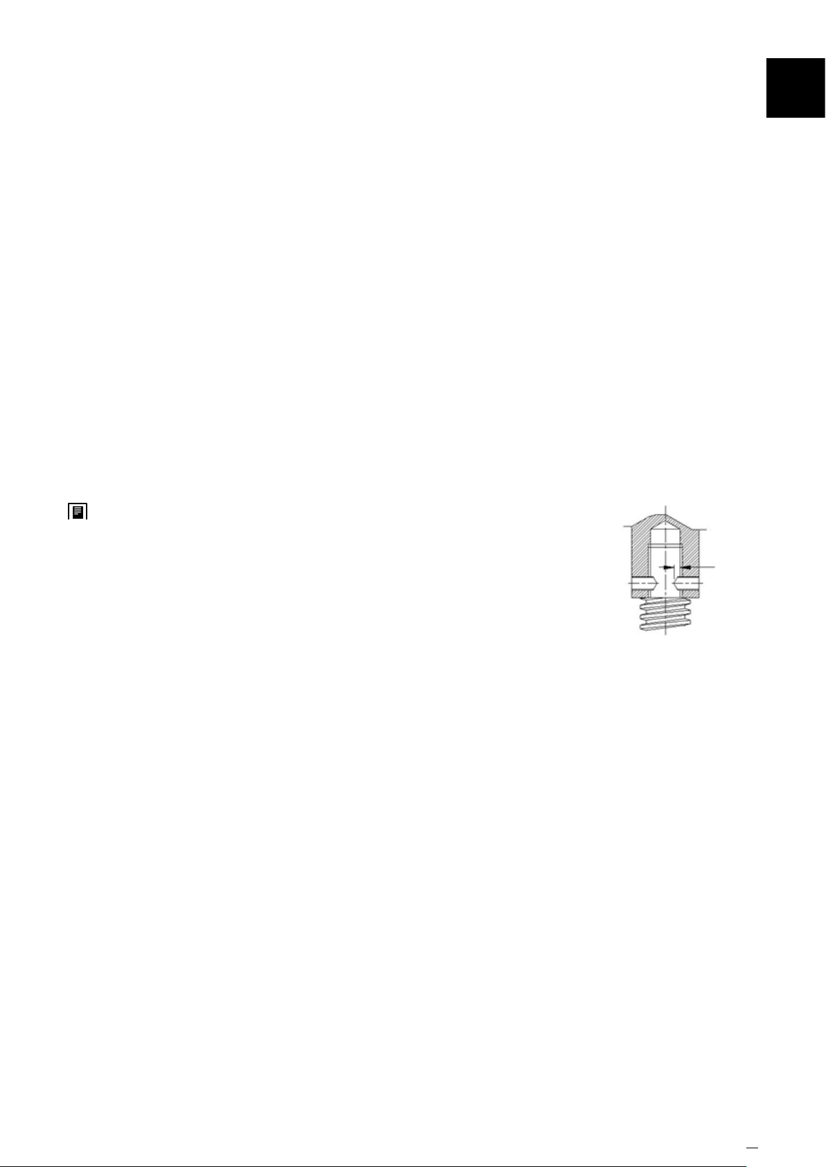
4.2.2 Thread the detachable end on to the lead screw and tighten up as hard as possible without
damaging the components.
4.2.3 Select a twist drill which is a free t in the tapped holes of the detachable end. Using these holes
as a drill guide, drill dimple only into the lead screw. Clean out swarf and remove detachable
end. Select another drill which matches the set screw diameter and, using the drill dimples as
a guide, drill into the lead screw a full diameter depth of 1mm below the root diameter of the
threads. Ret detachable end.
4.2.4 Fit the knurled point set screws (supplied with detachable ends) rmly in place ensuring that
point of set screws make contact with bottom of drill dimples. Secure the set screws with
chemical thread locking compound (e.g. Loctite).
4
4.2.5 If screw jacks with keyed lead screws are involved, and it is required to
line up the clevis ats or top plate holes, etc., in a xed relationship
to the worm shaft centre line, it will be necessary to face the underside
of the detachable end to obtain the required relationship. This operation
should be done carefully as only a few hundredths of a mm (thousands
of an inch) removed from the attachment is equivalent to a fair amount
of rotational movement. After the correct relationship has been obtained
with the attachment rmly tightened up, proceed to install the screw jack
in accordance with this manual.
1mm deep
drill dimples
www.powerjacks.com 11
Page 12
Installation4
4.3 Unpacking and installation
4.3.1 Remove the E-Series screw jack(s) from their container. Dispose of the packaging material and
the desiccant in an environmentally friendly way.
4.3.2 If it is necessary and in order to avoid damages, please use soft straps to transport or mount the
screw jack.
4.3.3 For translating screw jacks in order to avoid damages, do not attach the straps to the lead screw
but to the lead screw end tting, cover pipe or to the screw jacks gearbox. Where possible lift
vertically.
4.3.4 For rotating screw jacks in order to avoid damages, do not attach the straps to the lead screw
but to the nut on the lead screw or to the screw jacks gearbox. Where possible lift vertically.
4.4 Mounting
4.4.1 Before starting assembly work, check the directions of rotation of all jacks, gearboxes and drive
motors with regard to the required direction of travel of each jack in the application.
4.4.2 All components must be carefully aligned, as alignment errors increase stress and power
consumption and lead to overheating and premature wear.
4.4.3 When installing screw jacks, ensure that the mounting face is at and square to the guides of
the load, to within 0.4/1000 millimetres.
4.4.4 Before attaching the drive unit, the screw jack should be turned through its entire stroke by
hand, without load. Variations in the amount of force required and/or marks on the screw or
guides indicate alignment errors. Loosen the relevant mounting bolts and adjust positioning
until the correct alignment is achieved.
4.4.5 All mounting bolts must be re-tightened after a short period of operation.
4.4.6 Mount the screw jack by xing the screw jack body to the structure by either its standard base
mounting points or via a mounting accessory like a trunnion. The screw end or nut should be
xed to the moving part of the structure (or vice versa).
4.4.7 Verify that the structural attachment that connects to the screw jack end tting or nut is aligned
throughout the screw jack stroke before connecting to the screw jack.
4.4.8 Take care when tting couplings. A blow on a shaft end could cause gear set damage.
4.4.9 Shaft alignment is critical, check on installation
4.4.10 Bellows Boots
4.4.10.1 Push the bellows over the lead screw and attach the collars with the jubilee clips provided. Be
careful not to rip or tear the bellows boot.
12 www.powerjacks.com
Page 13

4.4.11 Drive Motor
4.4.11.1 Power Jacks recommend that when you purchase a screw jack requiring a motor mounted
directly to the screw jack this is purchased as a complete item from Power Jacks. The motor is
then pre-assembled to the screw jack. If you have opted to t a motor yourself below is a typical
procedure for common motor types.
4.4.11.2 Before mounting the drive motor, check the direction of rotation of the screw jack drive shafts
relative to the linear motion of its lead screw. Also check the operation of any limit switches
tted to the unit.
4.4.11.3 Place the motor into the mounting position next to the screw jack.
4.4.11.4 Connect the motor to the power source and switch on the motor. Check the direction of rotation,
in association with the safety limit switches (if necessary, change the direction of the motor
shaft rotation).
4.4.11.5 Remove the worm shaft and ange ensuring that the worm shaft seal is not damaged as this
must be reused (alternatively order spares).
Installation
4
4.4.11.6 Attach the motor adapter ange to the shell / body of the screw jack, using 4 set screws.
4.4.11.7 Fit the worm shaft seal.
4.4.11.8 Typically a exible coupling with elastomeric element is used to connect the two drive shafts.
4.4.11.9 Attach one hub of the coupling half to the worm shaft of the screw jack.
4.4.11.10 Push the elastomeric element (spider insert) onto the coupling hub now on the screw jack.
4.4.11.11 Mount the second coupling hub onto the drive shaft of the motor.
4.4.11.12 Attach the motor to the motor adapter ange using 4 screws. Remember to radially orientate
the motor to the correct position for your application.
4.4.12 Limit Switches – Fitted To Cover Pipe
4.4.12.1 Power Jacks recommend that when you purchase a screw jack requiring limit switches mounted
directly to the screw jack this is purchased as a complete item from Power Jacks. The limit
switches are then pre-assembled to the screw jack provided suitable to transport. However
always reset and check limit switch operation when installing the screw jack. The following
procedure is for limit switches tted to the cover pipe of the screw jack with an adjustable clamp
ring.
4.4.12.2 Detach the corresponding clamping ring on the cover pipe by loosening the mounting bolt.
4.4.12.3 Move the limit switch into the desired position.
4.4.12.4 Clamp the ring by tightening the mounting bolt.
4.4.12.5 Check the position of the limit switch by turning the screw manually and checking that the
switches triggers at the desired screw jack stroke position.
4.4.12.6 If necessary, repeat the procedure.
www.powerjacks.com 13
Page 14
Installation4
4.4.13 Limit Switches – Rotary Cam Type (RLS)
4.4.13.1 Power Jacks recommend that when you purchase a screw jack requiring a Rotary cam type
Limit Switch (RLS) mounted directly to the screw jack this is purchased as a complete item from
Power Jacks. The RLS unit is then pre-assembled to the screw jack. If you have opted to t a
RLS unit yourself below is a typical procedure for common RLS unit types. However always reset
and check limit switch operation when installing the screw jack.
4.4.13.2 Before mounting the RLS unit, check the direction of rotation of the screw jack drive shafts
relative to the linear motion of its lead screw.
4.4.13.3 Place the RLS unit into the mounting position next to the screw jack.
4.4.13.4 Remove the worm shaft end ange ensuring that the worm shaft seal is not damaged as this
must be reused (alternatively order spares).
4.4.13.5 Attach the RLS adapter ange to the shell / body of the screw jack, using 4 set screws.
4.4.13.6 Fit the worm shaft seal.
4.4.13.7 Typically a exible beam coupling is used to connect the two drive shafts.
4.4.13.8 Attach the beam coupling to the worm shaft of the screw jack.
4.4.13.9 Attach the RLS unit to the adapter ange using 4 screws. Make sure that the drive shaft of the
RLS unit fully engages in the beam coupling. Tighten the clamp screw of the beam coupling.
Remember to radially orientate the RLS unit to the correct position for your application.
4.5 Regulations
The following regulations must be complied with:
• The relevant local regulations for the prevention of accidents.
• Generally recognized safety regulations.
• National regulations.
14 www.powerjacks.com
Page 15
5.1 Operational Recommendations
5.1.1 Select a screw jack which has a rated capacity greater than the maximum load that may be
imposed on it.
5.1.2 The screw jacks should have a greater raise than is needed in the actual installation. Should
it be necessary to operate the screw jacks at the extreme limits of travel it should be done
cautiously.
5.1.3 It is important that the lead screws should not be closed below the specied closed height
dimension of the screw jacks, otherwise serious damage may result to the worm gear.
5.1.4 Lead screw end stops are to prevent over-travel or loss of screw. These are not load supporting
and should be treated as an emergency device only and must not be allowed to come into
contact with the worm gears during normal working cycles otherwise serious damage will
result to worm gears and bearings.
5.1.5 The maximum worm shaft speed for these screw jacks should not exceed 500 R.P.M. for heavy
loads. Refer to Power Jacks Limited for higher worm shaft speeds for lighter loads.
Operation
5
5.1.6 The lead screws should not be permitted to accumulate dust and grit on the threads. If possible,
lead screws should be returned to the closed position (retracted) when not in use.
5.1.7 If equipped with bellows boot the boot must not be compressed bellow its minimum height
(consult Power Jacks product literature or engineers).
5.2 Operational Features
5.2.1 How a Rotating Screw Jack Works
The rotation of the worm shaft causes the worm gear to rotate. For rotating screw jacks the lead
screw is xed to the worm gear and they rotate at the same speed. As the worm gear turns, the
friction forces on the screw thread act to turn the nut also. The greater the load on the screw
jack unit, the greater the tendency of the nut to turn. If the nut turns with the screw, it will
not raise the load. Therefore the nut needs to be xed to a structure to prevent rotation. The
restraining torque required for the structure, also known as the "lead screw key torque" can be
found in product literature or requested from Power Jacks.
5.2.2 How a Translating Screw Jack Works
The rotation of the worm shaft causes the worm gear to rotate. For translating screw jacks
the worm gear is threaded to accommodate the lead screw thread. As the worm gear turns,
the friction forces on the screw thread act to turn the screw also. The greater the load on the
screw jack unit, the greater the tendency of the screw to turn. If the screw turns with the nut
(worm gear), it will not raise the load. In those cases where a single unit is used, and where the
load cannot be restrained from turning, it is necessary to use a screw jack with an anti-rotation
mechanism (keyed screw jack). Lead screw key torque (refer to product literature or requested
from Power Jacks) must be checked as excessively heavy unguided loads could break the Antirotation mechanism (key).
www.powerjacks.com 15
Page 16
5 Operation
5.2.3 Anti-Backlash Screw Jack – When To Use
5.2.4 Input Torque Required for a Screw Jack
5.2.5 Maximum Input Power & Speed for a Screw Jack
For reduced axial backlash of the lead screw in the screw jack select a model with the "AntiBacklash" mechanism. This is typically used when the load direction changes from tension to
compression and minimal axial backlash is required. This design is only available for translating
screw jacks. It can be combined with Anti-Rotation mechanism as well.
The input torque for a single screw jack depends on the load, the worm gear ratio, type of screw
(machine screw, ball screw or roller screw) and the pitch of the lead screw. Torque values are
listed in the individual product specication charts based on capacity loads. For loads from 25%
to 100% of screw jack model capacity, torque requirements are approximately proportional to
the load.
Note: The input torque, as well as the efciency and side load ratings, is the same for both
translating screw and rotating screw jacks.
The input power to the screw jacks should not exceed the power rating shown in the
specications table. Maximum input speed in rpm (revolutions per minute) to a screw jacks
worm shaft should not exceed 1800 rpm for E-Series screw jacks.
5.2.6 Efciency of a Screw Jack
Screw Jack model efciencies are listed in the individual product specication charts.
5.2.7 Expected Life of a Screw Jack
The life expectancy of a screw jacks lead screw, bearings, nut and worm gear set varies
considerably due to the extent of lubrication, abrasive or chemical action, overloading, excessive
heat, improper maintenance, etc. For detailed life calculations consult Power Jacks Ltd.
5.2.8 Screw Jack with Anti-Rotation (Keyed) Mechanism
This design is only available for translating screw jacks. If the structure/object connected to
the lead screw is not prevented from rotating or the lead screw is not always in contact with the
structure then a screw jack with an "Anti-Rotation" mechanism (keyed) should be used.
5.2.9 Standard Screw Jacks How To Prevent The Load from Rotating
For multiple screw jack systems, x the lead screw end ttings (e.g. top plate or clevis) to the
common member being lifted by all the units. For single screw jack applications, bolt the lead
screw end tting (e.g. top plate or clevis) to the load and ensure the load is guided to prevent
rotation.
A guided load is always recommended to ensure that the screw jack does not receive any side
load and so guidance can be scaled suitably for the load without altering the screw jack design
unnecessarily. Note that an external guidance system can provide a higher restraining "key"
torque than compared to an anti-rotation mechanism in a screw jack.
5.2.10 Self-Locking of Screw Jacks
Screw Jacks with 24:1 gear ratios are considered self-locking in most cases. Consult Power
Jacks for a recommendation specic to your application.
All screw jacks with double start lifting screws are considered not to be self-locking.
Screw Jacks considered not self-locking will require a brake or other holding device.
16 www.powerjacks.com
Page 17
5.2.11 Shock Loads on a Screw Jack
Shock loads should be eliminated or reduced to a minimum, if they cannot be avoided, the screw
jack model selected should be rated at twice the required static load.
For severe shock load applications, the load bearings can be replaced with heat-treated steel
thrust rings which is an option available from Power Jacks. Note this will increase the input
torque by approximately 100%.
5.2.12 Axial Backlash in a Screw Jack
5.2.12.1 Backlash in Standard Machine Screw Jacks
Machine screw jacks have backlash due not only to normal manufacturing tolerances, but to the
fact that there must be some clearances to prevent binding and galling when the screw jack unit
is under load. Usually, the axial backlash is not a problem unless the load on the screw jack unit
changes between compression and tension. If a problem does exist, then a unit with the antibacklash feature should be considered.
5.2.12.2 Screw Jacks with the Anti-Backlash Device
The anti-backlash device reduces the axial backlash between the lead screw and nut assembly
to a regulated minimum. As the backlash will increase as the lead screw thread on the gear
wears the anti-backlash device can be adjusted to remove this normal condition.
Operation
5
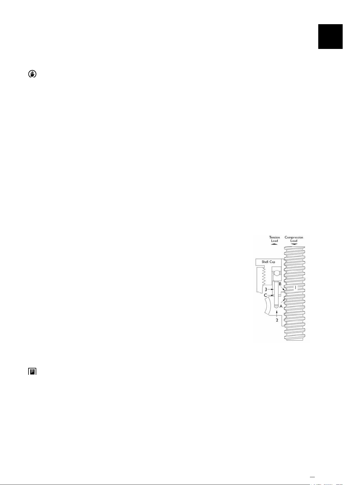
5.2.13 How the Anti-Backlash Device Works
When the screw (1) is under a compression load, the bottom of its
thread surfaces are supported by the top thread surfaces of the worm
gear (2) at point (A). The anti-backlash nut (3), being pinned to the
worm gear and oating on these pins and being adjusted downward
by the shell cap, forces its bottom thread surfaces against the upper
thread surfaces of the lifting screw at point (B). Thus, backlash
between worm gear threads is reduced to a regulated minimum.
When wear occurs in the worm gear threads and on the load carrying
surfaces of the lifting screw thread, the load carrying thickness of the
worm gear thread will be reduced. This wear will create a gap at point
(B) and provide backlash equal to the wear on the threads.
Under compression load, the lifting screw will no longer be in contact
with the lower thread surface of the anti-backlash nut. Under this
condition, backlash will be present when a tension load is applied.
The anti-backlash feature can be maintained simply by adjusting the shell cap until the desired
amount of backlash is achieved.
To avoid binding and excessive wear do not adjust lifting screw backlash to less than 0.025mm
(0.001”). This will reduce the calculated separation (C) between the anti-backlash nut and worm
gear and will reduce the backlash between the worm gear threads and the lifting screw to the
desired minimum value.
When separation (C) has been reduced to zero, wear has taken place. Replace the worm gear
(2) at this point. This feature acts as a built in safety device which can be used to provide wear
indication for critical applications.
5.2.14 Column Strength of the Screw Jack
Column strength of a screw is determined by the relationship between the screw length and its
diameter. For column strength charts consult product literature or Power Jacks.
www.powerjacks.com 17
Page 18
Operation5
5.2.15 Side Loads on a Screw Jack
Screw jacks are designed primarily to move and position loads and any side loads (loads not
acting axially on lead screw) should be avoided. The units will withstand some side loads,
depending on the diameter of the lifting screw and the extended length of the lifting screw.
Where side loads are present, the loads should be guided and the guides, rather than the screw
jacks, should take the side loads - particularly when long raises are involved. Even a small side
load can exert great force on the housings and bearings and increase the operating torque and
reduce the life expectancy.
5.2.16 Allowable Duty Cycle of Screw Jack
Because of the efciency of conventional worm gear screw jacks, the duty cycle is intermittent
at rated load. At reduced loading, the duty cycle may be increased. The high performance
S-Series screw jacks have higher thermal efciencies allowing generally 50% higher duty cycles
than conventional worm gear screw jacks. For detailed analysis consult Power Jacks Ltd.
5.2.17 Maximum Operating Temperatures For E-Series Screw Jack
Normal operation at ambient temperatures of up to 90ºC. Operations above 90ºC will require
special lubricants. For temperatures above 90ºC, the life of even special lubricants is limited.
Therefore consult Power Jacks on your application. For temperatures above 90ºC, advise Power
Jacks of full particulars of the duration of such temperatures. Power Jacks suggest that a
lubricant manufacturer be consulted for type of grease and lubrication schedule. As a general
rule, the screw jack unit should be shielded to keep ambient temperatures to 90ºC or less.
5.2.18 Minimum Temperature For E-Series Screw Jacks
With the standard lubricant and materials of construction, the screw jacks are suitable for use
at sustained temperatures of -20ºC. Below -20ºC, low temperature lubricant should be used
and no shock loads are present. Power Jacks application engineers must be consulted in these
instances for a recommendation. Screw Jacks with standard material of construction and
lubrication may be safely stored at temperatures as low as -55ºC.
5.2.19 Thermal / Heat Build-Up in a Screw Jack as it is operated
The duty cycle, the length of the screw, the magnitude of the load, and the efciency of the
screw jack all have a direct inuence on the amount of heat generated within the screw jack.
Long lifts can cause serious overheating. Note that high duty S-Series screw jacks have a higher
thermal capacity than conventional worm gear screw jacks.
5.2.20 Screw Jacks to Pivot a Load
A screw jack can be built to pivot a load by two methods:
5.2.20.1 Double Clevis Screw Jack
The screw jack can be furnished with a clevis at both ends (commonly referred to as a double
clevis screw jack). The bottom clevis is welded to the bottom end of an extra strong cover pipe,
which is tted to the base of the screw jack. This cover pipe still performs its primary function of
encasing the lifting screw in its retracted portion.
5.2.20.2 Clevis - Trunnion Mounting
The screw jack is tted with the pivot end tting (e.g. Clevis) on the lead screw and a trunnion
mount adapter is bolted to the screw jacks base plate.
The design of the structure in which these types of screw jacks are to be used must be
constructed so that screw jack can pivot at both ends. Use only direct compression or tension
loads, thereby eliminating side load conditions
18 www.powerjacks.com
Page 19
5.2.21 Corrosion Resistant Properties
Screw Jacks can be supplied with alternative materials and/or paint specications for high
corrosive areas. These options include stainless steel, chrome plating, Electro-nickel plating,
epoxy paint, etc. Check the unit specication is suitable before installation.
5.2.22 Using Screw Jacks within a Rigid Structure or Press
Power Jacks recommend that the screw jack selected has a greater capacity than the rated
capacity of the press or of the load capacity of the structure. We also recommend that a torque
clutch or similar device be used to prevent overloading of the screw jack unit. Unless these
precautions are taken, it is possible to overload the screw jack without realising it.
5.2.23 Screw Jack Drift after Drive Motor is Switched Off
The screw jack will drift after the motor drive is switched off unless a brake of sufcient capacity
is used to prevent it. The amount of drift will depend upon the load on the screw jack and the
inertia of the rotor in the motor.
For machine screw jacks with no load, the amount of drift will depend upon the size and speed
of the motor. For example, a 1500 RPM input directly connected to a screw jack without a load
will give on average 35mm to 60mm of drift; a 1000 RPM input will give about 1/2 as much drift.
Note that the drift varies as the square of the velocity (RPM). The drift of the screw jacks screw
can be controlled by using a magnetic brake on the motor. Variations of drift will also be seen if
the motor drives the screw jack via a reduction gearbox.
Operation
5
5.2.24 Screw Jacks Operation where Vibration is Present
Screw Jacks will operate in areas with vibration, however the vibration may cause the lead
screw to “creep” or “inch” under load. For applications involving slight vibration, select the
higher of the worm gear ratios. If considerable vibration is present, use a motor equipped with a
magnetic brake, which will prevent the screw jack from creep and/or back-driving.
5.2.25 Use of Screw Jacks Fitted With Emergency Stop Disc
To prevent over travel of the lead screw a stop disc or nut can be tted to a screw jack that is
hand operated. It should not be used as a full power stop.
5.2.26 Use of Screw Jacks Fitted With Emergency Stop Nut
For motor driven units it is possible for the full capacity of the screw jack or even a greater force
(depending on the power of the motor) to be applied against the stop. These stops are called
"full power stop nuts". They must only be used as an emergency device and if such a condition
occurs an assessment made to discover why it happened in order to carry out preventative
action. If the full power stop nut is used at full load in an emergency it might be driven into the
unit jamming so tightly that it must be disassembled in order to free it.
It is recommended that external stops are tted where possible, however they must only be
used as a last resort (Note - limit switches are one possible solution to constrain screw jack
movement safely - consult Power Jacks for system advice). Under ideal conditions where a slip
clutch or torque limiting device is used, a stop pin or stop nut may be used - but Power Jacks
should be consulted.
5.2.27 Screw Jack System Arrangements
Perhaps the greatest single advantage of Power Jacks screw jacks is that they can be linked
together mechanically, to lift, lower, move or position in unison. Typical mechanical system
arrangements link 2, 4, 6 or 8 screw jacks together and are driven by one motor. As an
alternative screw jacks can be individually driven by electric motors and with suitable feedback
devices such as encoders be synchronised electronically by a control system.
www.powerjacks.com 19
Page 20
Operation5
5.2.28 Connecting Screw Jacks in Series
The number of screw jacks that can be connected in series is limited by input torque
requirements on the rst worm shaft in the line. For the E-Series the torque on the worm shaft
of the rst screw jack should not exceed 300% of its rated full load torque (this does not include
the 200kN screw jacks which are rated at 200%).
5.2.29 Efciency of a Multiple Screw Jack System
In addition to individual device efciencies, the efciency of the screw jack arrangement must
be taken into consideration. The arrangement efciency allows for misalignment due to slight
deformation of the structure under load, for the losses in couplings, bearings, and for a normal
amount of misalignment in positioning the screw jacks and gearboxes. For efciency values
consult Power Jacks product literature or engineers.
5.2.30 Screw Jack Fitted with 3rd Party Accessories
If your screw jack is tted with a device not manufactured by Power Jacks then please consult
the provided manual for this device.
20 www.powerjacks.com
Page 21
6.1 General Maintenance Notes
6.1.1 Maintenance and replacement work must be done by an expert maintenance technicians trained
in the observance of applicable laws on health and safety at work and the special ambient
problems attendant on the installation.
6.1.2 Before doing any work on the unit, the operator must rst switch off power to the screw jacks
drive system and ensure that it is out of service, as well as taking all necessary precautions
against it being accidentally switched on again or its parts moving without warning.
6.1.3 All additional environmental safety precautions must be taken (e.g. elimination of residual gas
or dust, etc.).
6.1.4 Before doing any maintenance work, activate all safety equipment and, if necessary, inform
persons working in the vicinity. In particular, mark off the area around the unit(s) and prevent
access to any equipment, which, if activated, might be the cause of unexpected health and safety
hazards.
6.1.5 Replace worn components with original spare parts only.
Maintenance
6
6.1.6 Use the lubricants (oil and grease) recommended by the Manufacturer.
6.1.7 When working on the units, always replace gaskets and seals with new original ones.
6.1.8 If a bearing requires replacement, it is good practice to also replace the other bearing
supporting the same shaft.
6.1.9 Power Jacks recommend replacing the lubricant after all maintenance work where a unit has
been dismantled (completely or partially).
6.1.10 The above instructions are aimed at ensuring efcient and safe operation of the E-Series screw
jack unit.
6.1.11 The Manufacturer declines all liability for injury and damage to components due to the use of
non-original spare parts and non-routine work, which modies the safety requirements without
the express prior authorisation of the Manufacturer.
6.1.12 Refer to the specic spare parts list when ordering spare parts for products.
6.1.13 Do not dump polluting liquids, worn parts and maintenance waste into the environment. Dispose
of all such materials as stipulated by applicable legislation.
www.powerjacks.com 21
Page 22
6 Maintenance
6.2 Regular Maintenance
Also refer to section 6.3
6.2.1 Lubrication Of The Screw Jack
6.2.1.1 The screw jacks are shipped packed with grease (unless otherwise called for) which should be
6.2.1.2 IMPORTANT NOTE – Lubricant suitability is dependent on duty cycle and ambient temperature.
6.2.1.3 The maintenance engineer should establish a lubrication programme based on the screw jack’s
6.2.1.4 The lead screw requires a light grease lm to be applied at Installation. The lead screw should
sufcient for one month of normal operation.
However in general recommended lubricants in section 7 are suitable for operation in an
ambient temperature of -10ºC to +50ºC. If in doubt consult with Power Jacks prior to installation
and operation.
duty and use.
not be over greased.
6.2.1.5 Note excessive grease should be avoided.
6.2.1.6 It is recommended that the screw jack be tted with bellows or covers to protect the exposed
screw from contamination from dirt and debris.
6.2.1.7 If the screw jack or its system is tted with a brake ensure that under no circumstances
lubricant gets into the brake as this can cause brake failure due to loss of friction.
6.2.2 Lubrication Intervals - General
6.2.2.1 Regularly check and top up lubrication in the E-Series screw jack(s).
6.2.2.2 Refer to section 7 for recommended lubricants.
Item Operation Type Lubrication Interval Grease Type
1 Normal
2 Arduous
6.2.2.3 Rotating screw jacks are not supplied with lubricant on the lead screw as the screw thread is
exposed. Before operation suitable grease must be applied to the screw.
Check & lubricate as required
every 1 month
Check & lubricate as required
every 1 week
Extreme Pressure Grease or equivalent. Refer Section 7 Table 1
Molybdenium disulphide grease or equivalent. Refer Section 7 Table 2
6.3 Check Unit Operational Performance
6.3.1 Remove dust / dirt / debris deposits from the unit(s).
6.3.2 Check that noise at constant load does not vary. Excessive vibration or noise can indicate wear of
a gear in a gearbox or failure of a bearing.
6.3.3 Check for lubricant leaks from the gaskets/seals, caps and casings.
22 www.powerjacks.com
Page 23
6.3.4 Check all bolted joints/couplings for wear, deformation or corrosion and tighten them down fully
without over tightening.
6.3.5 A periodic check of backlash between lead screw and worm gear (translating screw jacks) or
lead screw and nut (rotating screw jacks) is recommended to check wear on internal threads
of worm gear. Backlash in excess of 25% thread thickness indicates that a replacement will be
necessary to replace the worm gear / nut assembly.
6.3.6 If driven by an electric motor check the power absorption and voltage against the nominal
values given on the motor’s nameplate.
6.3.7 The gearbox section of the E-Series screw jack operates with a maximum case temperature of
90°C. If this temperature is exceeded Power Jacks should be consulted.
6.4 Repair of Power Jacks E-Series Screw Jacks
6.4.1 Power Jacks recommend that a E-Series screw jack is returned to Power Jacks for repair. A full
inspection and repair service is available.
Maintenance
6
6.5 RebuildProcedure
Power Jacks recommend the following procedures for assembly and disassembly of a E-Series screw jack.
6.5.1 Tag critical parts to facilitate reassembly.
6.5.2 Place all screws, washers and other small xing components in a tagged bag/box with the
associated product on which they are to be used referenced on the tag.
6.5.3 Mark mating surfaces to ensure proper meshing.
6.5.4 Clean and lubricate all parts as required.
6.5.5 All seals must be replaced when rebuilding.
6.5.6 All screws, washers and other small component parts must be replaced if damaged in any way.
6.5.7 Replace damaged or “frozen” lubrication ttings with new ones.
6.5.8 General Dis-mantle & Rebuild Procedure
6.5.8.1 Remove the lead screw from the screw jack body.
6.5.8.2 Unscrew the fasteners xing the shell cap.
6.5.8.3 Unscrew the shell cap and release the thrust bearings and worm gear.
6.5.8.4 Remove the worm shaft and ange (or circlip on 5kN & 10kN units) and gently tap out the worm
shaft from the opposite side with a soft mallet (e.g. rubber mallet).
6.5.8.5 Inspect and replace parts for wear or damage.
www.powerjacks.com 23
Page 24
6 Maintenance
6.5.8.6 When installing the worm shaft, use shims to establish the correct axial oat for the bearings
6.5.8.7 When screwing in the shell cap, establish the correct tightening torque by screwing down and
6.5.8.8 Lock the shell cap in place with locking fasteners.
6.5.8.9 For fasteners without spring lock washers use a chemical thread locking compound (e.g.
6.6 Replacing Parts
6.6.1 Do not hesitate to replace parts and/or components if they are not able to guarantee safe and
6.6.2 Never improvise repairs.
6.6.3 The use of non-original spare parts not only voids the warranty but also can compromise unit
Installed.
backing off the shell cap until the torque gure for the model is achieved.
Loctite).
reliable operation.
operation.
6.7 Required Tools
6.7.1 A press, coupling puller, impact extractor and common hand tools.
6.8 Lifting Units
6.8.1 When lifting, use accessories such as eyebolts, snap hooks, screw clamps, straps, ropes, hooks
etc. which are certied and adequate for the load. Use soft slings around the body of the jack
and do not lift by placing slings, chains or hooks around the input drive shafts.
6.8.2 The weight of the standard product and additional incremental weight amounts for the actual
stroke of the supplied unit are given in this manual in section 3.
6.9 Cleaning
6.9.1 External Cleaning
6.9.1.1 Clean all dust and process waste off the unit. Do not use solvents or other products, which are
incompatible with the construction material and do not direct high-pressure jets of water at the
unit.
6.9.2 Internal Cleaning
6.9.2.1 Remove lubricant from unit and do not re-use old lubricants.
24 www.powerjacks.com
Page 25
6.9.2.2 Flush a unit’s interior thoroughly with a light solvent before relling with new lubricant.
6.9.3 Warning
6.9.3.1 Provide adequate ventilation during the use of cleaning agents; avoid prolonged breathing of
6.9.3.2 Use clean hot water or a soap solution for general cleaning of painted surfaces.
6.9.3.3 Dry parts thoroughly after cleaning.
6.10 Painting
6.10.1 If a unit is to be painted, tape the nameplate, mounting surfaces and seal rings to prevent
fumes and contact with skin.
contact with solvent prior to painting.
Maintenance
6
www.powerjacks.com 25
Page 26
7 RecommendedLubricants
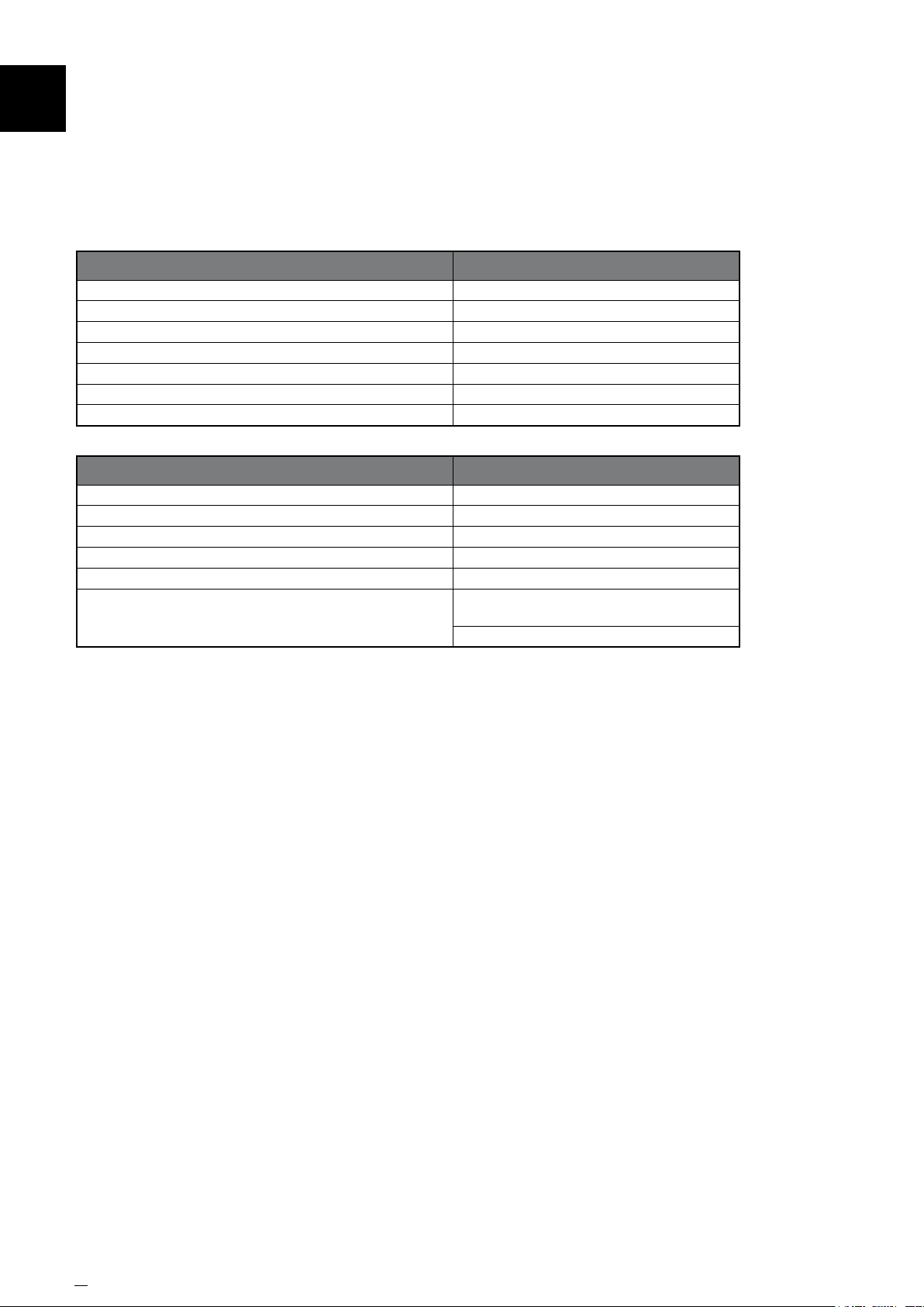
7 RecommendedLubricants
Table 1 - Normal Operation
Manufacturer Lubricant
Castrol Spheerol EPL2
Esso Beacon EP2
Gulf Gulfcrown EP2
Mobiloil Mobilux EP2
Power Petroleum BP Energrease LC2
Regent Texaco EP2
Shell Gadus S2V220AC2 (Alvania WR2)
Table 2 - Arduous Operation
Manufacturer Lubricant
Castrol Spheerol LMM2
Esso Beacon EP2 Moly
Mobiloil Mobilgrease XHP222 Special
Power Petroleum BP Energrease L2 1M
Regent Molytex 2
Shell
Shell Greases 5826
(Overseas)
Shell Alvania HDX2
26 www.powerjacks.com
Page 27
8.1 Recommendations
8.1.1 E-Series screw jacks are fully supported by Power Jacks. Spare parts and repairs are available.
8.1.2 It is recommended that when a screw jack is used in a production critical environment where
the cost of downtime far exceeds the cost of the screw jack a complete spare screw jack unit is
stocked by the customer. This allows the worn/damaged unit to be returned to Power Jacks for
repair by trained personnel. Alternatively it allows time for a new replacement screw jack to be
manufactured.
8.1.3 When enquiring about replacement parts or a complete unit please send the following
information to Power Jacks:
• Screw Jack Serial Number (found on product name plate - essential)
• Screw Jack Model Number (found on product name plate - essential)
• Original Purchase Order Number (if known).
• Power Jacks Sales Order Number (if known)
• Your Contact Details (essential)
Spare Parts
8
www.powerjacks.com 27
Page 28

9 Storage & Warehousing
9.1 General Storage Recommendations
Recommendations for storing the products are indicated below:
9.1.1 Store in a clean and dry environment, free from dirt and dust.
9.1.2 Screw Jack Storage Temperature: -10°C to +50°C.
9.1.3 Do not store the unit in excessively humid conditions or where it is exposed to the weather (do
not store outdoors).
9.1.4 Do not place product directly on the ground.
9.1.5 Store product(s) on a stable base and make sure that it is not subjected to accidental
displacement.
9.1.6 Store the unit(s) in the packaging provided for shipping (if allowed).
9.1.7 If products are to be stored for more than 6 months, the following additional precautions must
be taken:
9.1.7.1 Cover all machined external surfaces with a rust-proong product.
9.1.7.2 Fill the unit with appropriate lubricant if not supplied with lubricant.
9.1.8 Ensure that all screw jacks are stored in the fully retracted (closed) position.
9.1.9 All rotating parts should be turned by hand a few revolutions per month. If this is not practical,
then an external drive should be used to run the unit(s) for a few revolutions.
9.2 Long Term Storage
In the event that a screw jack(s) is to be stored for more than 6 months prior to installation/commissioning,
Power Jacks Ltd should be consulted to discuss preservation requirements.
28 www.powerjacks.com
Page 29

10.1 General Disposal Guidance
10.1.1 This must only be done by operators trained in the observance of applicable laws on health and
safety at work.
10.1.2 Do not dump non-biodegradable products, lubricants and non-ferrous materials (rubber, PVC,
resins, etc.) into the environment. Dispose of all such materials as stipulated by applicable
environmental protection legislation.
10.1.3 Do not attempt to re-use parts or components which appear to be in good condition after they
have been checked and/or replaced by qualied personnel and declared unsuitable for use.
Disposal of Units
10
www.powerjacks.com 29
Page 30

11
Warranty
11.1 WarrantyDenitions
When used in these conditions the following words have the meanings set out opposite them below:
Company: Power Jacks Limited
Contract: The contract between the Company and the Customer for the supply of the Goods.
Customer: The party to whom the Goods are to be supplied under the Contract
Goods: The goods to be provided under the Contract
Writing: Includes facsimile or electronic transmission and comparable means of communication
11.2 Warranty Statement
The Company warrants that any Goods sold by it under Power Jacks standard terms and conditions of sale
will be free from defects caused by faulty materials or poor workmanship but gives no warranty and makes no
representation whatsoever express or implied as to any other matters including without limitation condition
merchantability or tness for any purpose.
The Company shall incur no liability under this warranty unless:
• The Company is promptly notied in Writing upon discovery of any such defects by the Customer and
the Customer forthwith ceases to use the defective Goods unless otherwise authorised by the Company; and
• The defective item is immediately returned to the Company, transportation charges being prepaid by
the Customer or the Company is, at its option, given the opportunity to remedy any defect.
The Company's warranty as specied above is limited to a period of 12 months from the date of delivery (ex-works
Power Jacks) and its liability shall be limited to replacing, repairing or issuing credit at its option for any Goods
returned by the Customer within the aforesaid period.
The Company shall not be liable for consequential loss or damage by reason of any defect in (or failure to comply
with any written estimate of performance of) Goods supplied by the Company whether original or substituted.
The Customer will indemnify the Company against all third party claims made in respect of the Goods.
30 www.powerjacks.com
Page 31
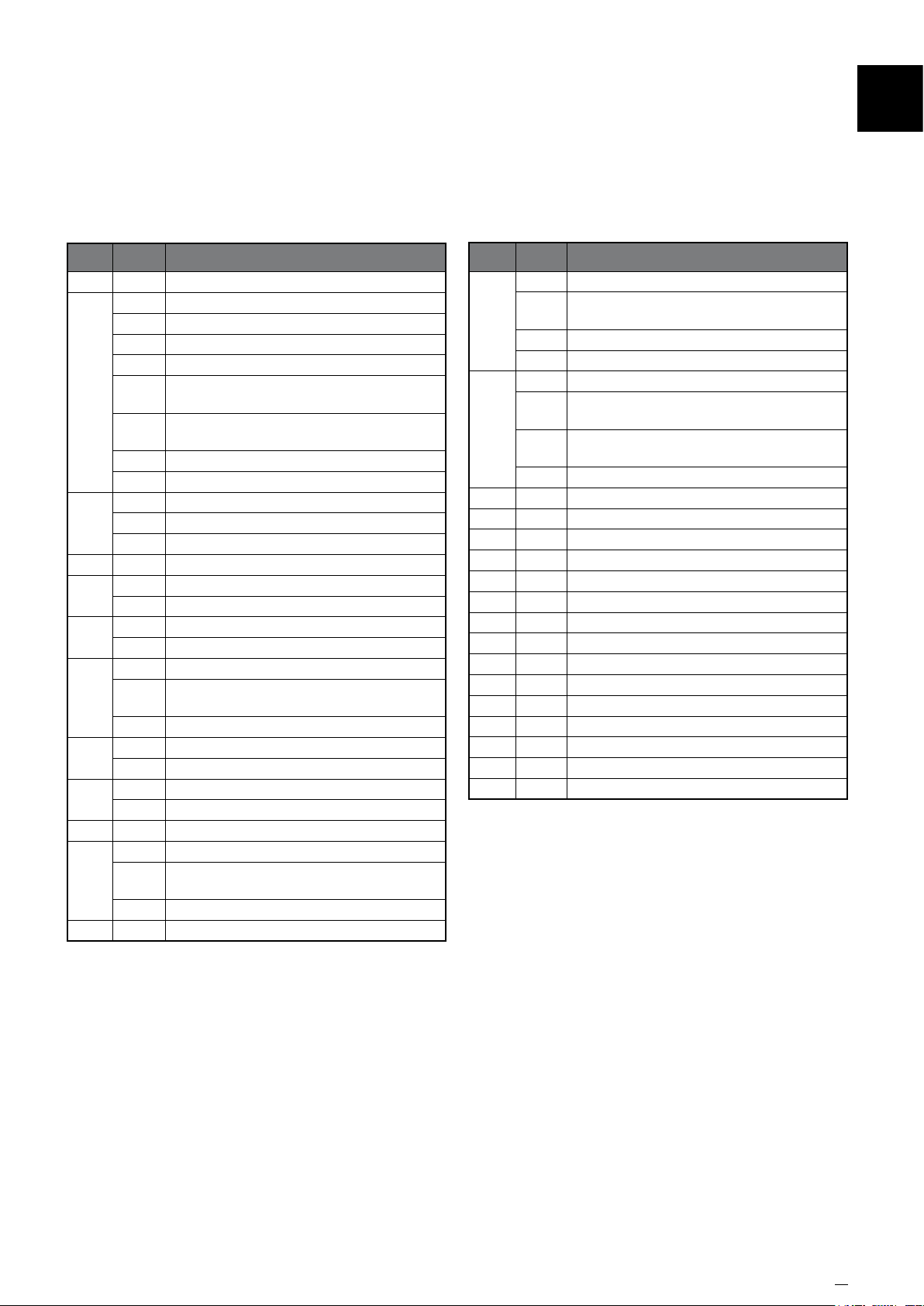
12.1 Parts List
GeneralAssembly&PartsList
12
Item Type Description
1 Shell
A Shell Cap - Upright Models
B Shell Cap - Inverted Models
C Shell Cap - Anti-Backlash Upright Models
D Shell Cap - Anti-Backlash Inverted Models
2
3
4 Worm Shaft
5
6
7
8
9
10 Flange
11
12 Key Adapter (Anti-Rotation)
Shell Cap - Anti-Rotation (Keyed) Upright
E
Models
Shell Cap - Anti-Rotation (Keyed) Inverted
F
Models
G Shell Cap - Rotating Upright Models
H Shell Cap - Rotating Inverted Models
A Worm Gear - Translating
B Worm Gear - Anti-Backlash
C Worm Gear - Rotating
A Lifting Nut
B Anti-Backlash Nut
A Bearing - Load
B Bearing - Worm Shaft
A Lifting Screw - Translating
Lifting Screw - Translating - Anti-Rotation
B
(Keyed)
C Lifting Screw - Rotating
A Cover Pipe - Translating Screw Type
B Plug/Cover Pipe
A End Fitting - Clevis
B End Fitting - Top Plate
A Guide Bush
Guide Bush (Plain) - Rotating Screw B
Upright
C Guide Bush - Rotating Screw - Inverted
Item Type Description
A Cap Screw (Keyed Shell Cap)
Cap Screw (Keyed Shell Cap - Inverted
B
50
51
52 Dowel Pin - Anti-Backlash models
53 Key (Work Shaft)
54 A Key (Lifting Screw/Shell Cap)
55 Lock nut (Lifting Screw)
56 Retaining Ring (Worm Shaft)
57 A Shim (0.1mm thick)
58 Oil Seal
59 A Washer (Lifting Screw - Lock nut)
60 Grease Nipple
61 Name Plate
62 Drive Screw (Name Plate)
Models)
C Cap Screw
D CapScrew (Key Adaptor)
A Set Screw (Shell Cap)
Set Screw (Shell Cap - Anti-Backlash
B
Models)
Set Screw (End Fixture) - 2 off at 180
C
degrees
D Set Screw (Lifting Screw - Lock nut)
B Drive Key (Lifting Screw)
B Shim (0.25mm thick)
B Lock Washer
C Lock Washer (Keyed Shell Cap)
Notes:
Not all parts are required for each screw jack, refer to general
arrangement drawing corresponding with the model of screw jack.
www.powerjacks.com 31
Page 32
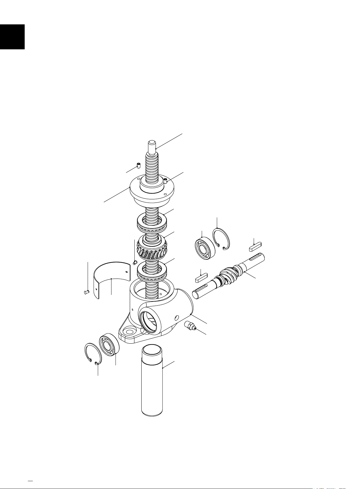
12
GeneralAssembly&PartsList
12.2 Translating Upright 5kN & 10kN
7A
62
2A
61
51A
62
6A
3A
6A
51A
56
6B
53
53
4
1
60
56
32 www.powerjacks.com
8A
6B
Page 33
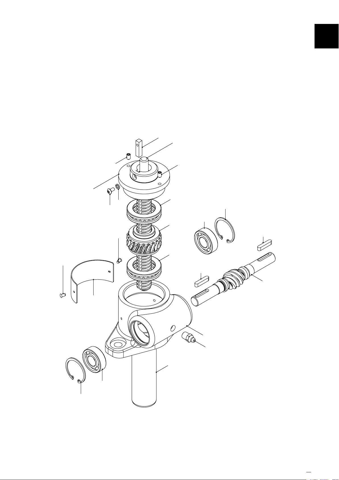
12.3 Translating Upright Anti-Rotation (Keyed) 5kN & 10kN
54A
7B
GeneralAssembly&PartsList
12
62
2E
61
51A
50B
59C
62
51A
6A
56
6B
3A
53
6A
53
4
56
1
60
8A
6B
www.powerjacks.com 33
Page 34
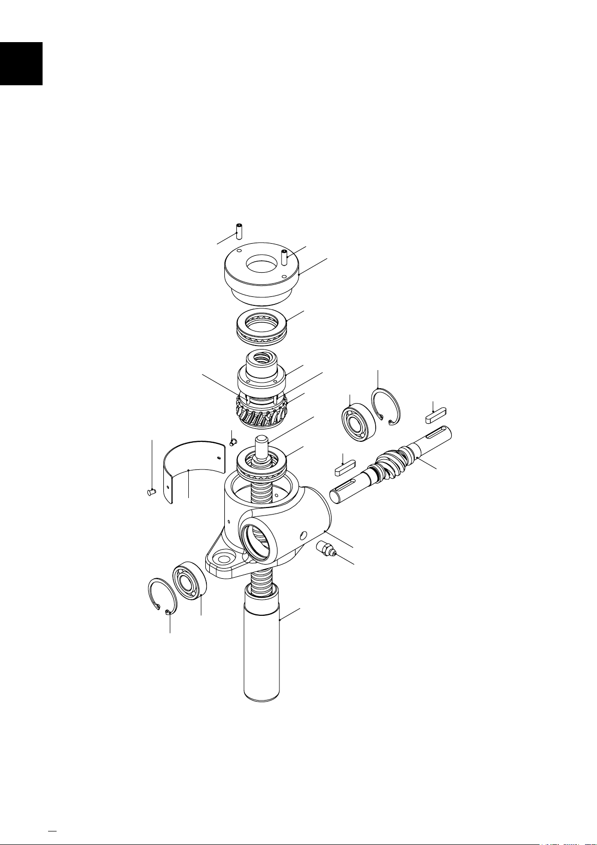
GeneralAssembly&PartsList12
12.4 Translating Upright Anti-Backlash 5kN & 10kN
62
61
52
51B
62
6A
5B
3B
6A
51B
7A
52
2C
56
6B
53
53
4
56
34 www.powerjacks.com
1
60
8A
6B
Page 35
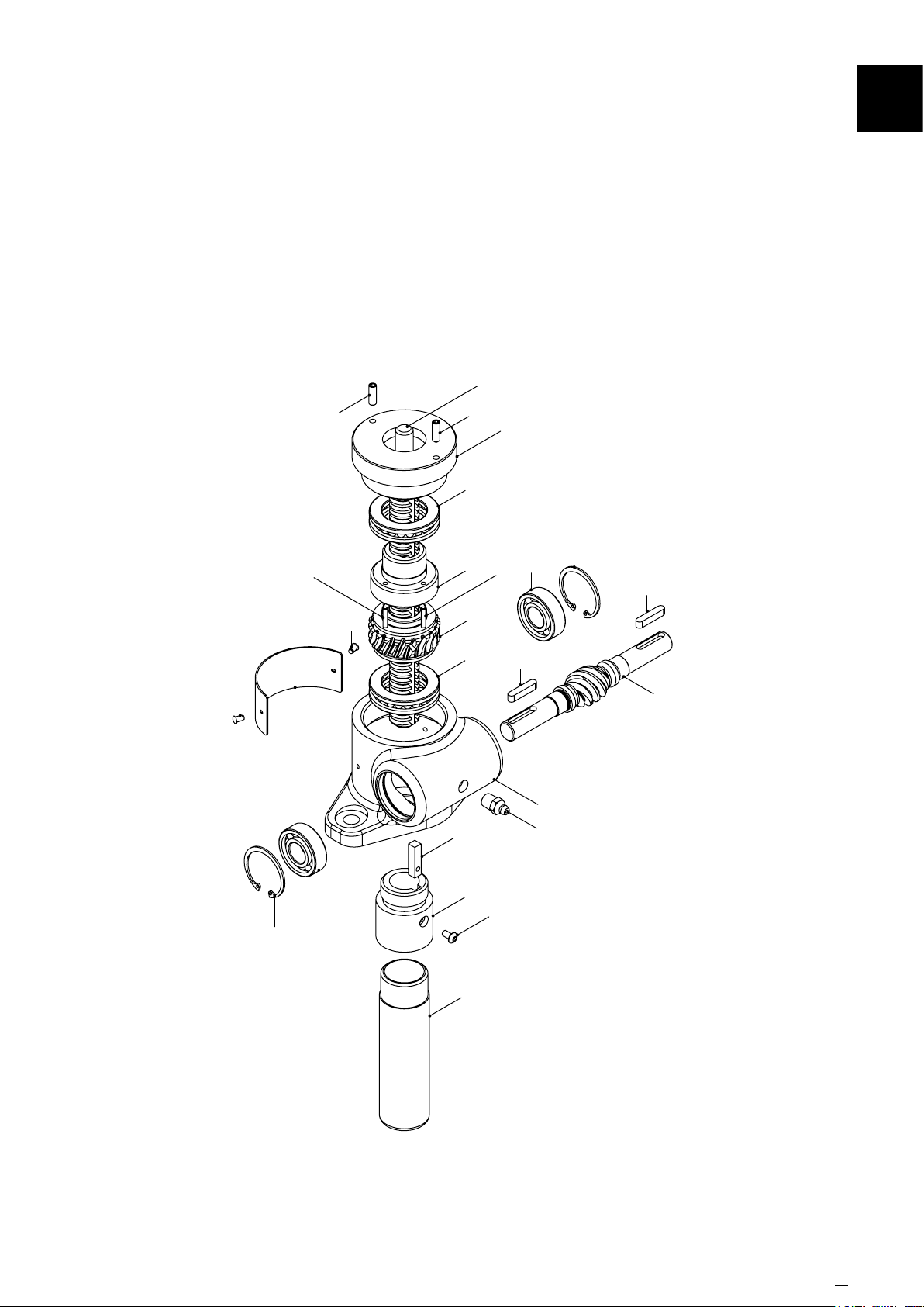
GeneralAssembly&PartsList
12.5 Translating Upright Anti-Backlash with Anti-Rotation (Keyed) 5kN & 10kN
7B
12
62
61
52
51B
62
51B
6A
5B
3B
6A
54A
2C
52
56
6B
53
53
4
1
60
56
6B
12
50B
8A
www.powerjacks.com 35
Page 36
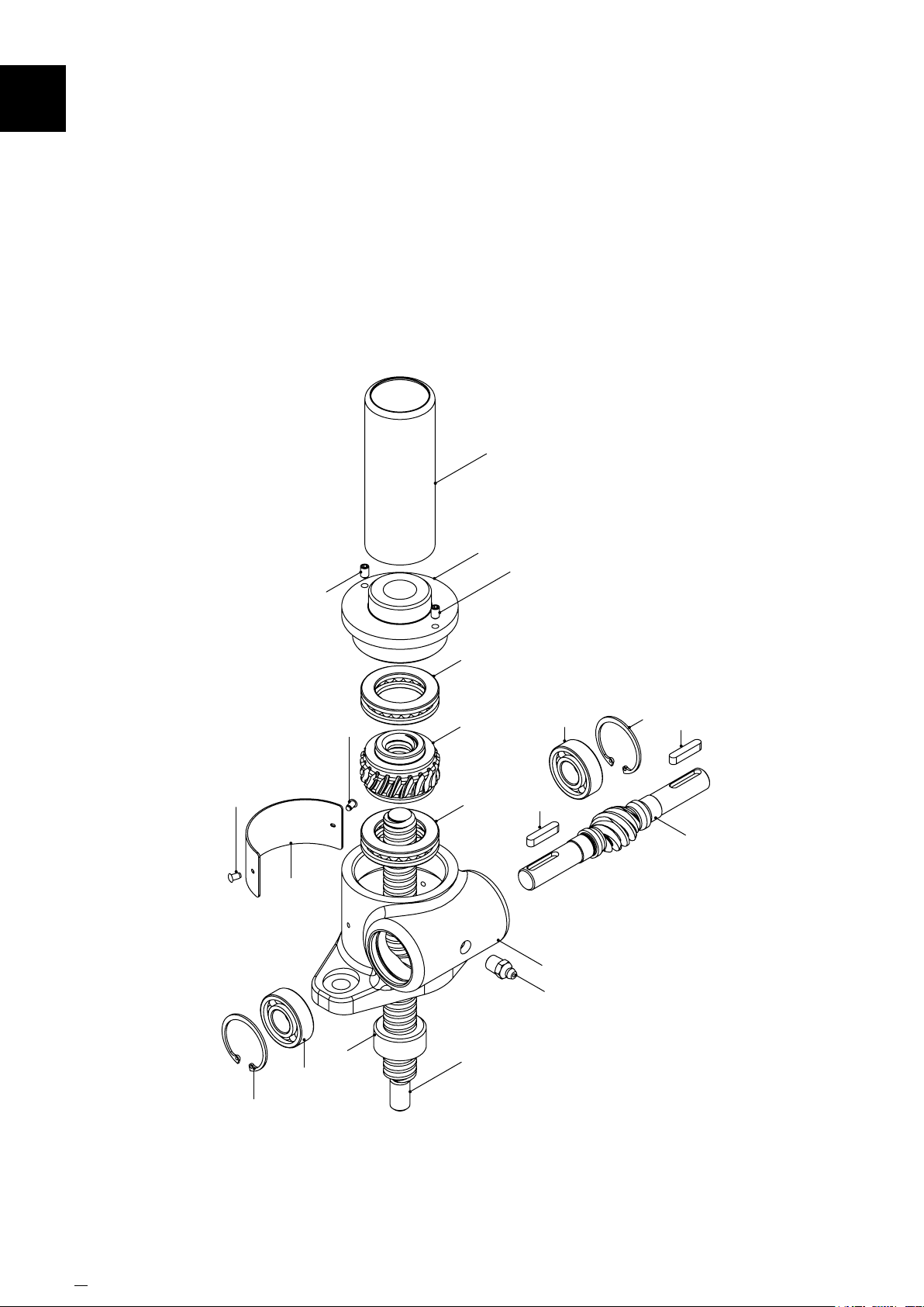
12
GeneralAssembly&PartsList
12.6 Translating Inverted 5kN & 10kN
8A
2B
51A
62
61
51A
62
6A
3A
6A
53
1
60
6B
56
53
4
56
36 www.powerjacks.com
6B
11A
7A
Page 37
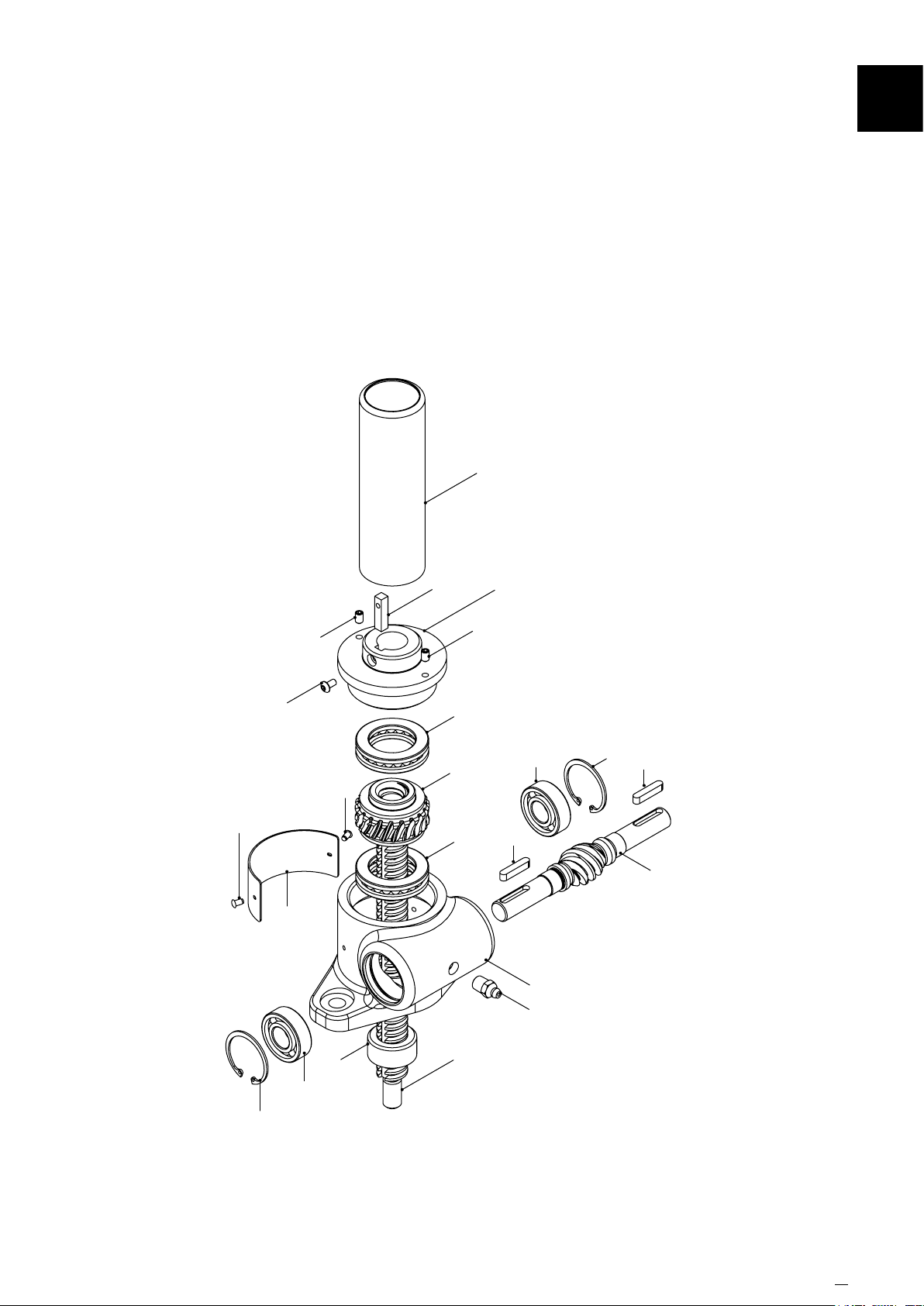
12.7 Translating Inverted Anti-Rotation (Keyed) 5kN & 10kN
8A
GeneralAssembly&PartsList
12
62
50B
61
51A
62
54A
3A
6A
6A
51A
2F
53
6B
1
60
56
53
4
56
6B
11A
7B
www.powerjacks.com 37
Page 38
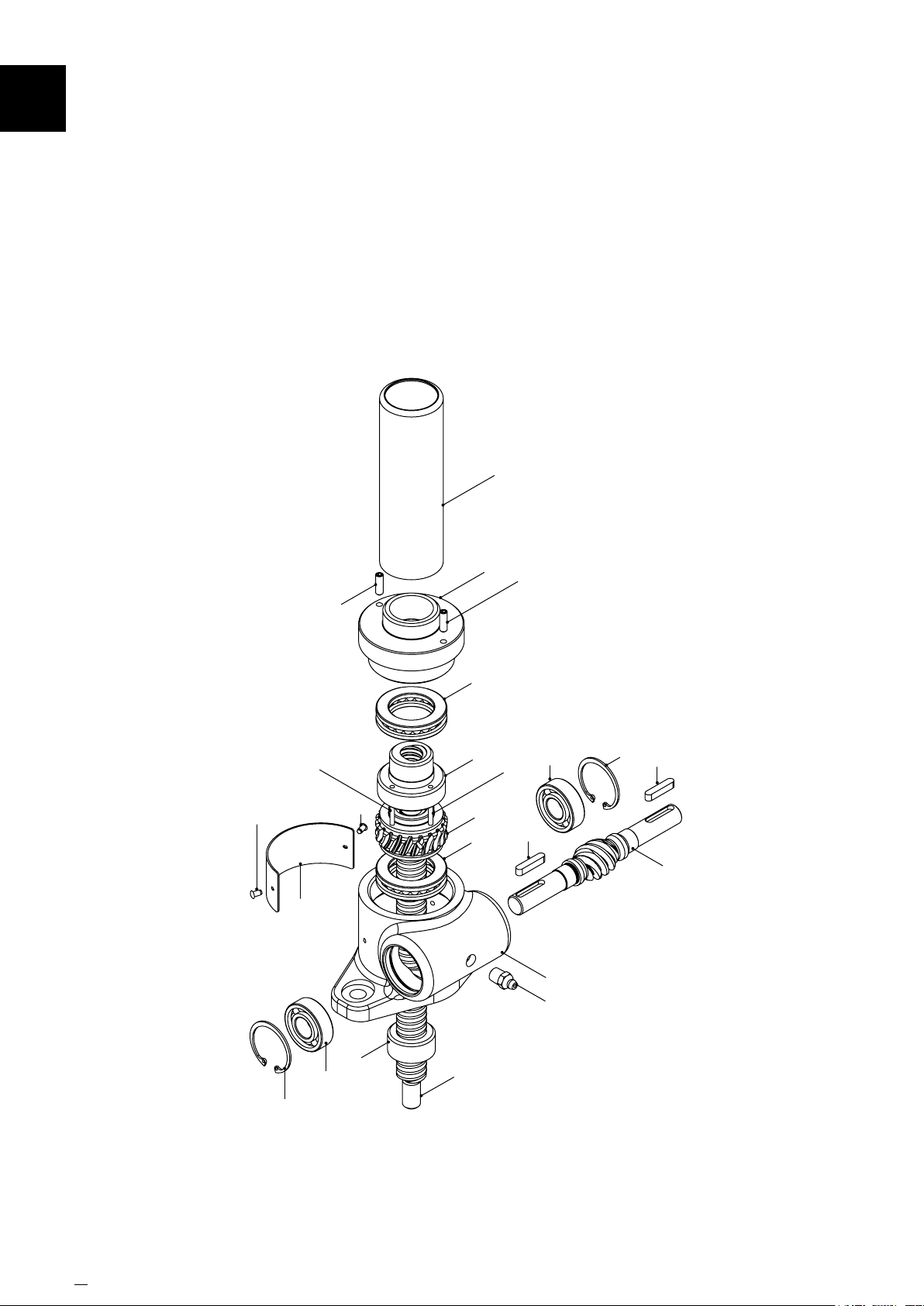
GeneralAssembly&PartsList12
12.8 Translating Inverted Anti-Backlash 5kN & 10kN
8A
62
61
51B
62
6A
5B
3B
6A
2D
5252
51B
53
6B
1
60
56
53
4
38 www.powerjacks.com
56
6B
11A
7A
Page 39
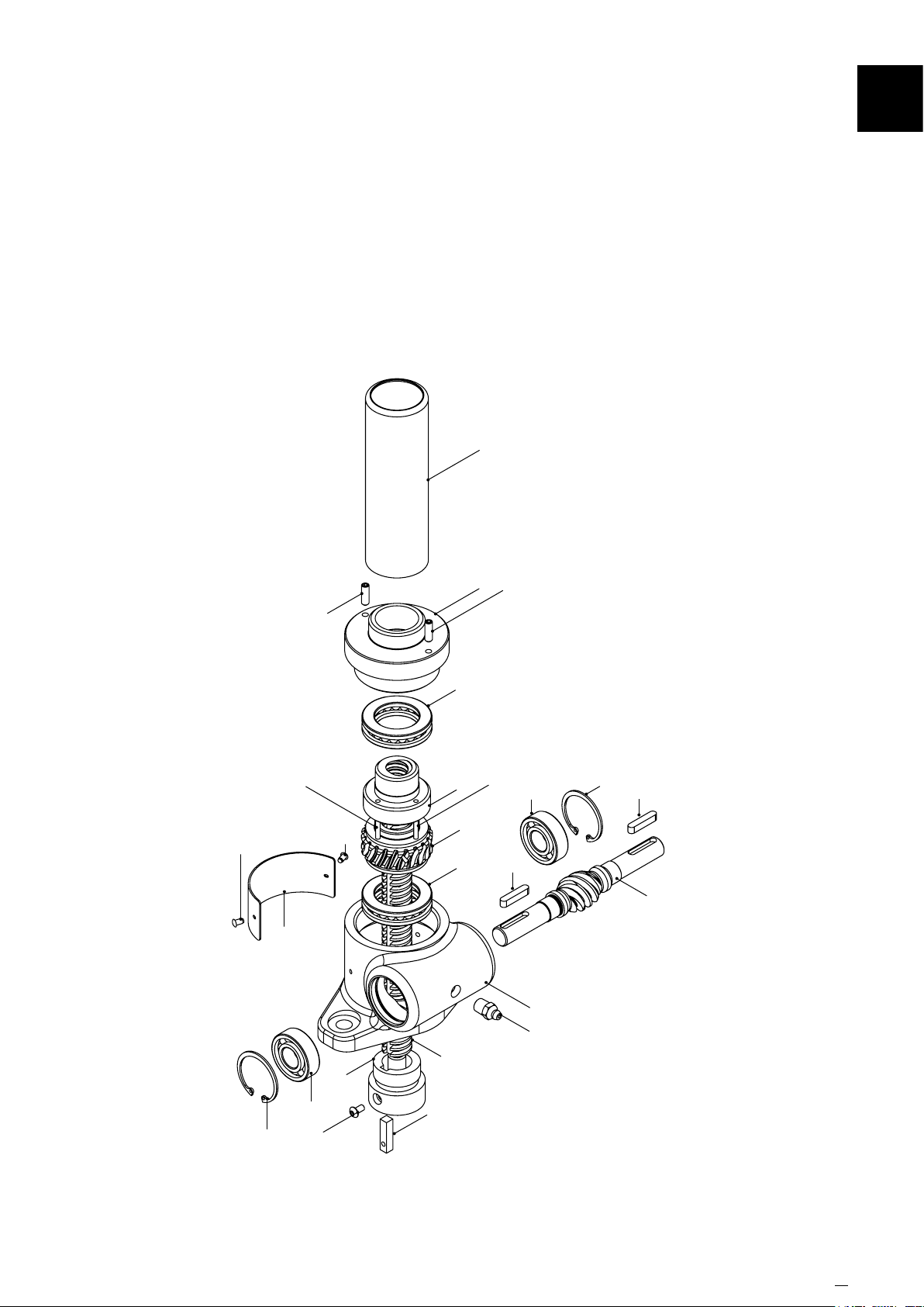
GeneralAssembly&PartsList
12.9 Translating Inverted Anti-Backlash with Anti-Rotation (Keyed) 5kN & 10kN
8A
12
62
61
52
51B
12
62
7B
6A
5B
3B
6A
2D
52
51B
53
6B
1
60
56
53
4
56
6B
50B
54A
www.powerjacks.com 39
Page 40
12
Section Name
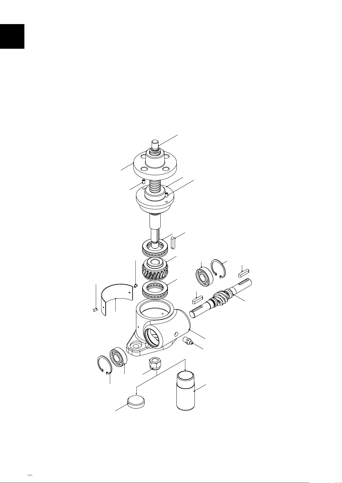
12.10 Rotating Upright 5kN & 10kN
7C
62
61
5A
51A
62
6A
3C
6A
2G
54B
51A
53
6B
56
53
4
40 www.powerjacks.com
56
8B
6B
1
60
55
8B (5kN unit only)
Page 41
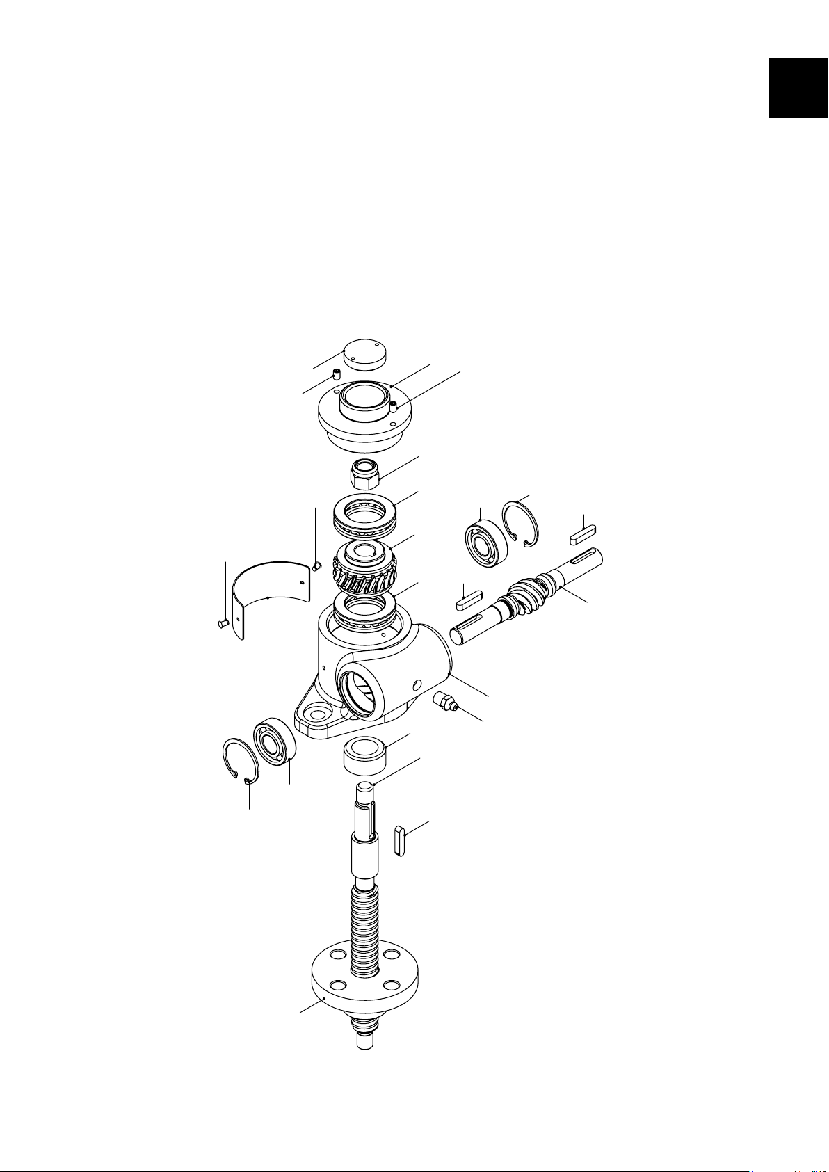
12.11 Rotating Inverted 5kN & 10kN
8B
51A
55
2H
51A
Section Name
12
62
56
61
6B
62
6A
3C
6A
11C
7C
54B
53
6B
56
53
4
1
60
5A
www.powerjacks.com
41
Page 42
12
GeneralAssembly&PartsList
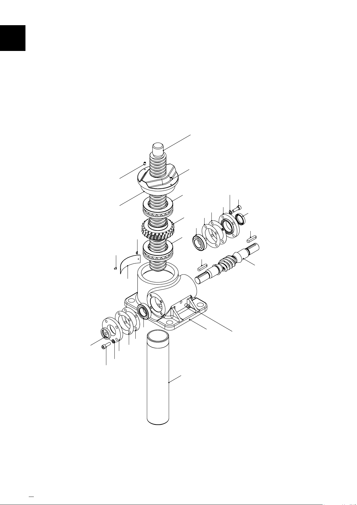
12.12 Translating Upright 25kN - 1000kN
7A
51A
51A
58
59B*
50C*
2A
62
10
61
57A
62
57B
6B
6A
3A
6A
8A
6B
57B
53
57A
1
59B*
50C*
10
58
53
4
60
* 4 per side, except 1000kN which has 6 per side
42 www.powerjacks.com
Page 43
GeneralAssembly&PartsList
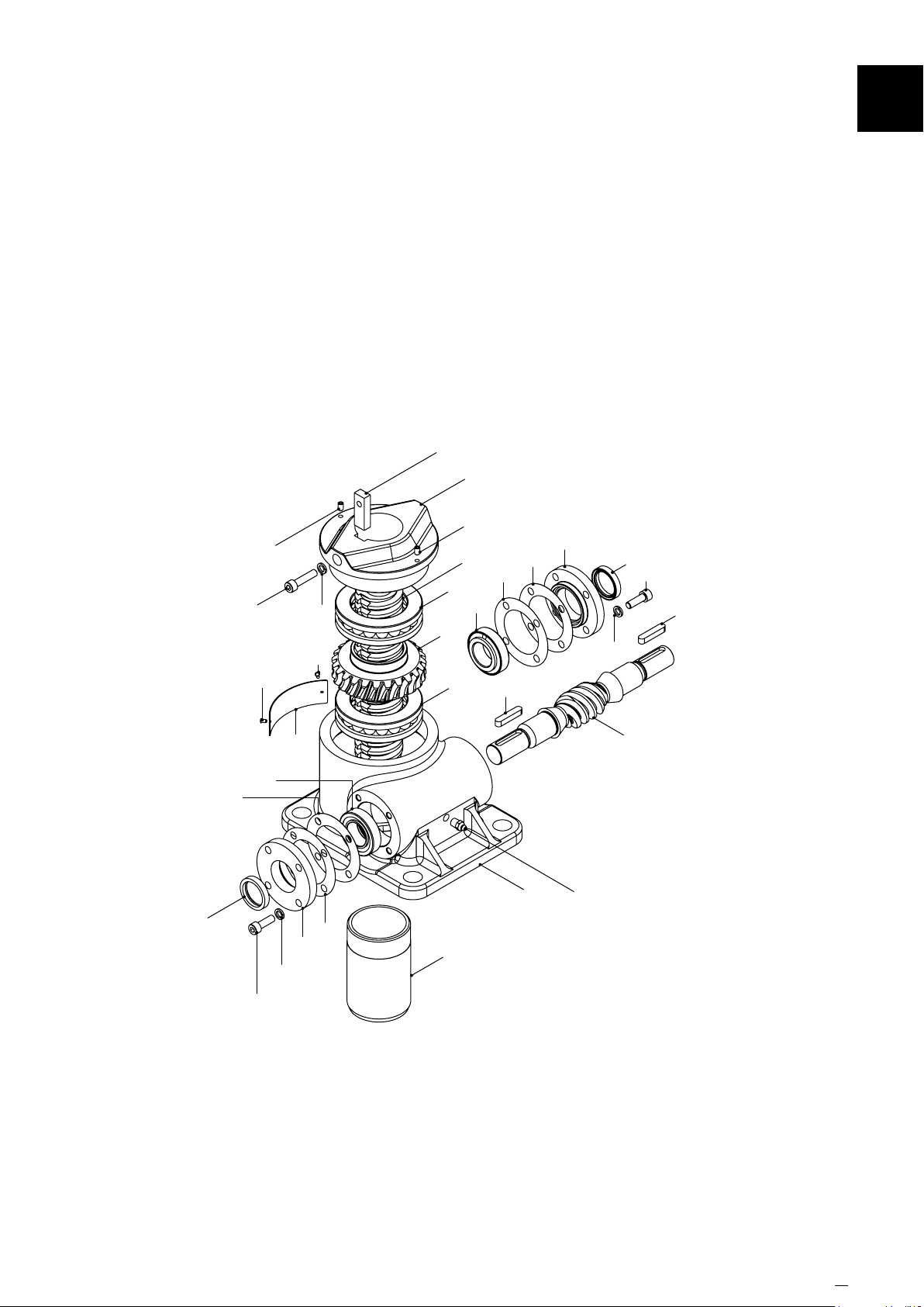
12.13 Translating Upright Anti-Rotation (Keyed) 25kN - 1000kN
54A
2E
51A
50A
51A
62
59C
62
7B
6A
6B
3A
6A
57A
57B
53
12
10
58
50C*
53
59B*
58
57B
6B
50C*
61
59B*
10
57A
8A
4
1
60
* 4 per side, except 1000kN which has 6 per side
www.powerjacks.com 43
Page 44
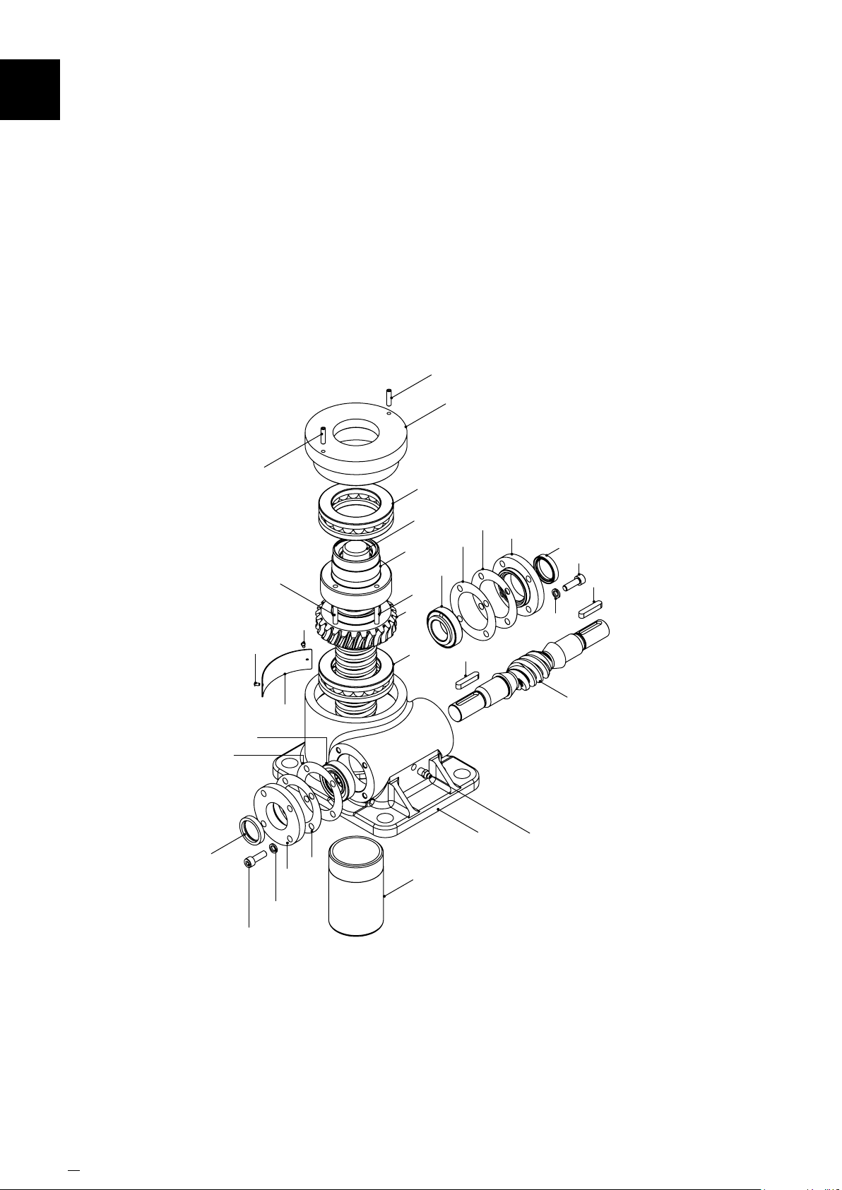
GeneralAssembly&PartsList12
12.14 Translating Upright Anti-Backlash 25kN - 1000kN
51B
2C
51B
6A
58
57B
6B
62
52
61
10
59B*
62
57A
5B
3B
6A
7A
52
8A
6B
57B
53
57A
1
10
58
50C*
53
59B*
4
60
50C*
* 4 per side, except 1000kN which has 6 per side
44 www.powerjacks.com
Page 45
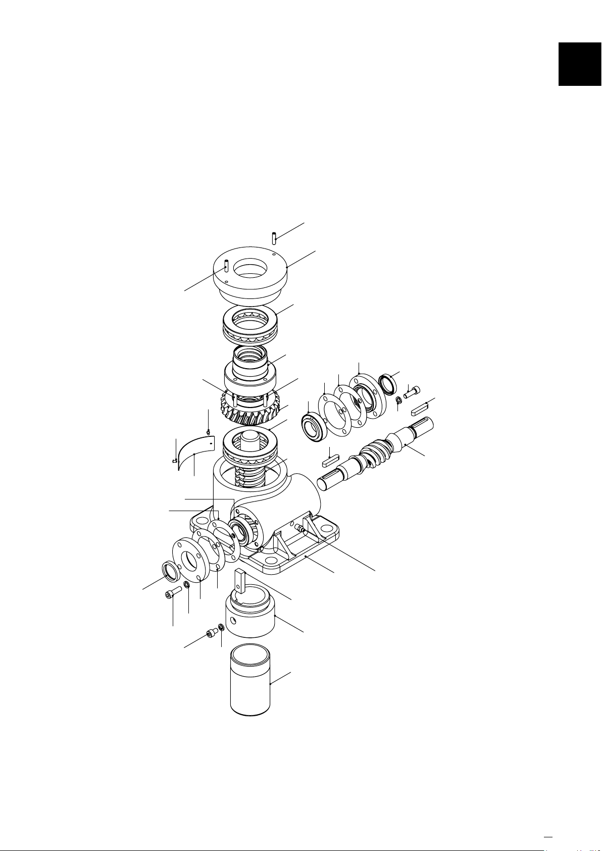
GeneralAssembly&PartsList
12.15 Translating Upright Anti-Backlash with Anti-Rotation (Keyed) 25kN - 1000kN
51B
2C
12
58
57B
51B
62
6B
50C*
50D
52
61
59B*
10
62
57A
59C
5B
3B
6A
7B
6A
52
54A
8A
6B
12
57B
53
57A
1
10
58
50C*
53
59B*
4
60
* 4 per side, except 1000kN which has 6 per side
www.powerjacks.com 45
Page 46
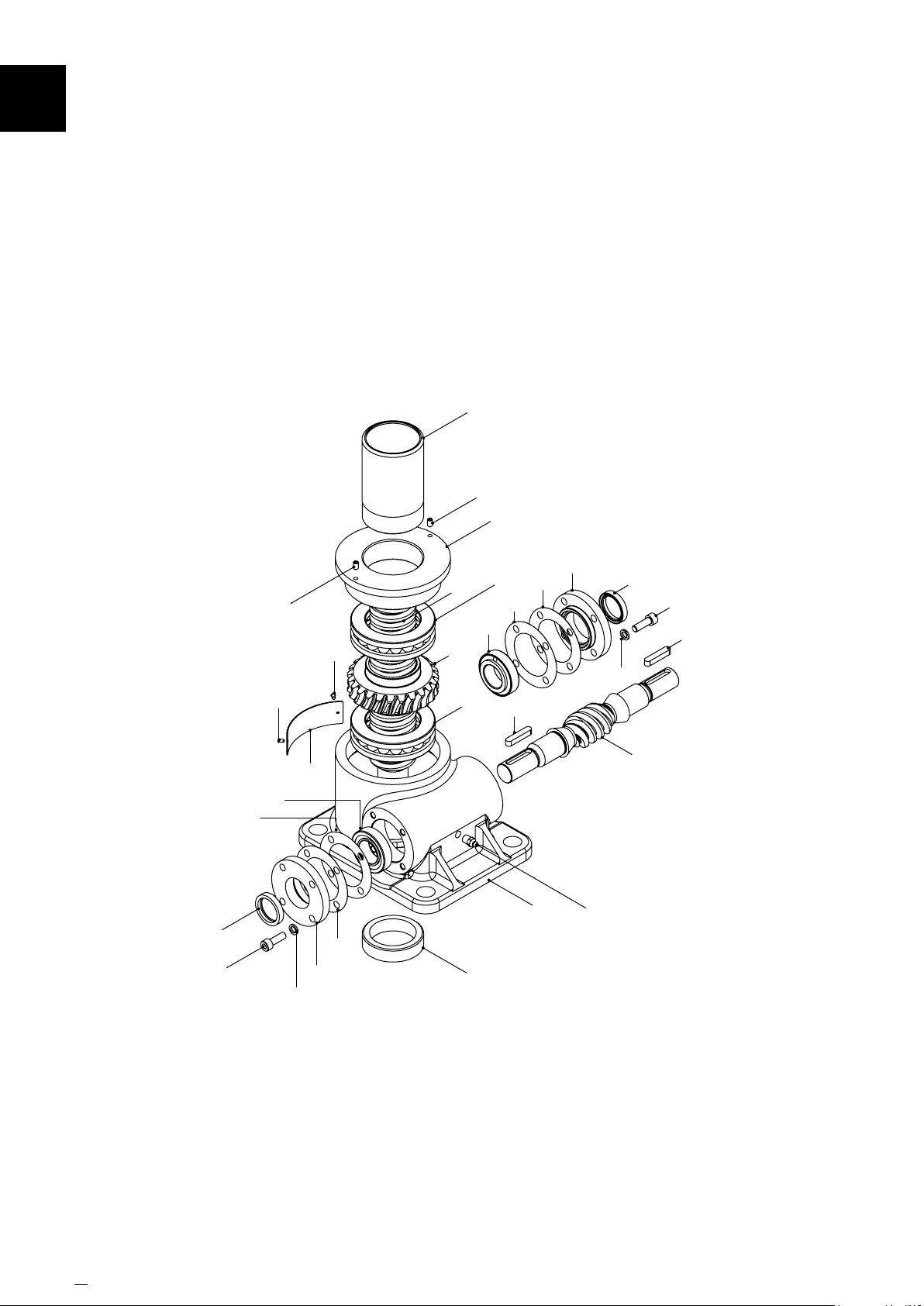
12
GeneralAssembly&PartsList
12.16 Translating Inverted 25kN - 1000kN
8A
51A
2B
58
50C*
57B
51A
62
6B
59B*
61
10
62
57A
7A
3A
6A
11A
6B
6A
57B
53
57A
1
10
58
50C*
53
59B*
4
60
* 4 per side, except 1000kN which has 6 per side
46 www.powerjacks.com
Page 47
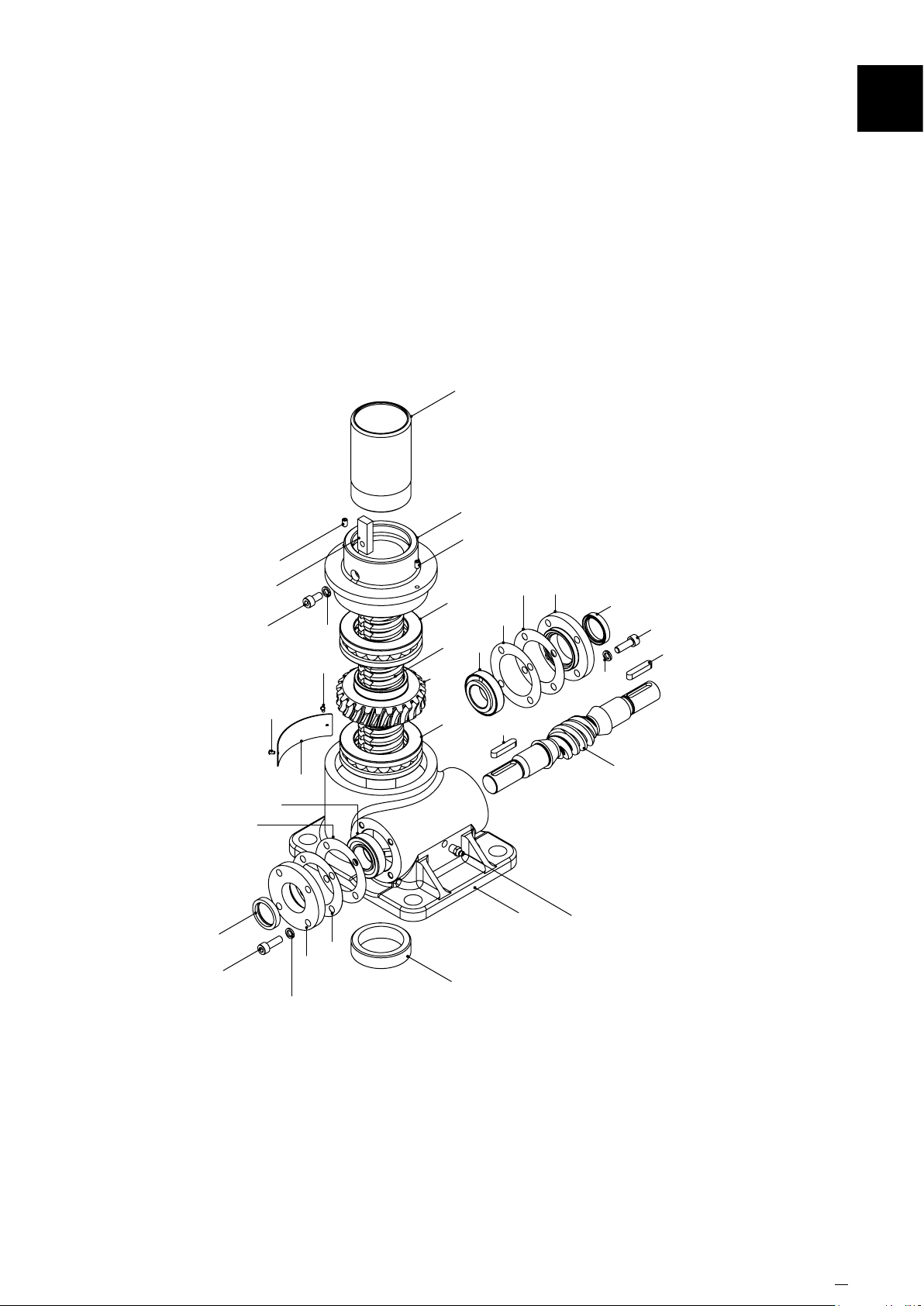
GeneralAssembly&PartsList
12.17 Translating Inverted Anti-Rotation (Keyed) 25kN - 1000kN
8A
2F
51A
51A
54A
50B
59C
62
3A
7B
6A
57B
6B
57A
10
12
58
50C*
53
59B*
58
50C*
57B
62
6B
61
59B*
10
57A
6A
11A
53
4
1
60
* 4 per side, except 1000kN which has 6 per side
www.powerjacks.com 47
Page 48
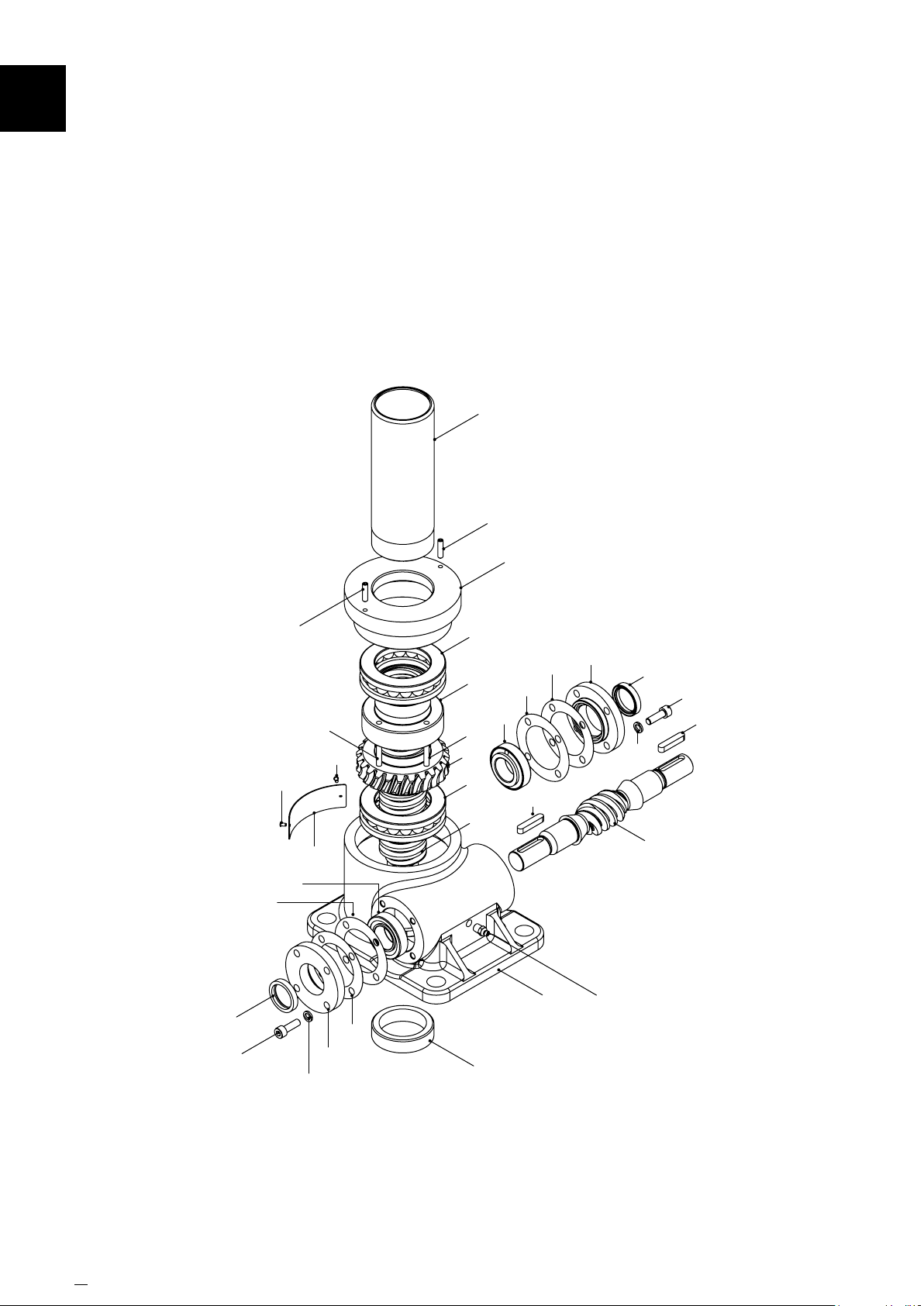
GeneralAssembly&PartsList12
12.18 Translating Inverted Anti-Backlash 25kN - 1000kN
8A
51B
58
50C*
57B
51B
62
6B
52
61
59B*
10
62
57A
52
3B
6A
6A
5B
7A
11A
6B
2D
57B
53
57A
1
10
58
50C*
53
59B*
4
60
* 4 per side, except 1000kN which has 6 per side
48 www.powerjacks.com
Page 49
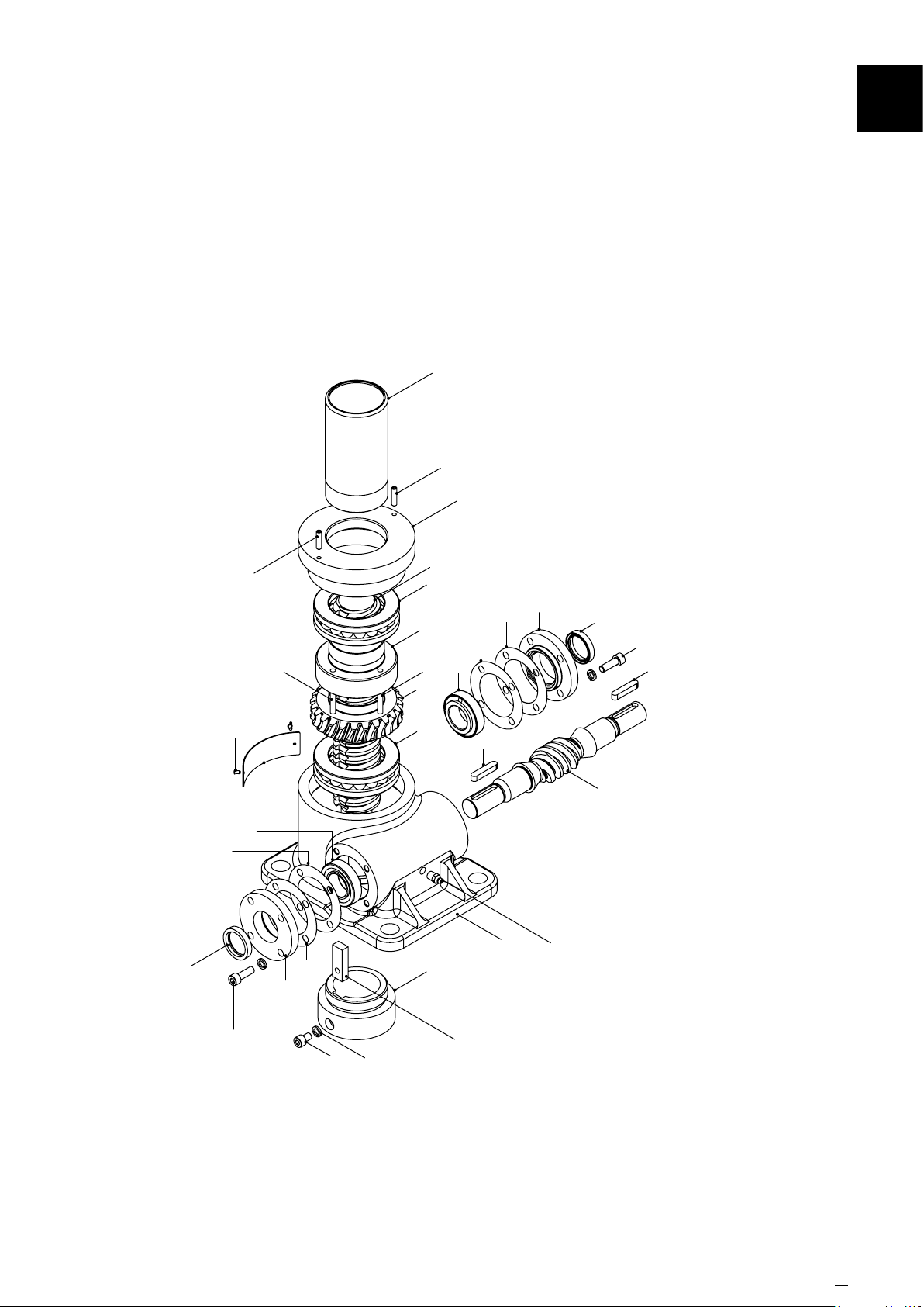
GeneralAssembly&PartsList
12.19 Translating Inverted Anti-Backlash with Anti-Rotation (Keyed) 25kN - 1000kN
8A
51B
2D
12
58
57B
51B
62
6B
61
52
10
62
57A
5B
3A
6A
52
7B
6A
12
6B
57B
53
57A
1
10
58
50C*
53
59B*
4
60
59B*
50C*
59C
50D
* 4 per side, except 1000kN which has 6 per side
54A
www.powerjacks.com 49
Page 50
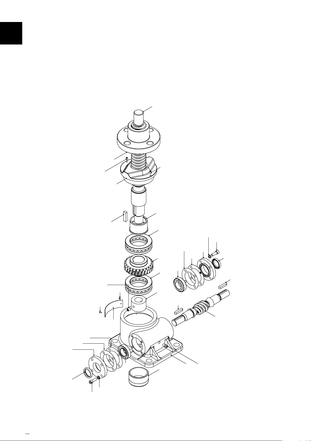
GeneralAssembly&PartsList12
12.20 Rotating Upright 25kN - 1000kN
7C
2A
51D
62
54B
5A
2G
62
2A
11B
6A
3C
6A
55
6B
53
57B
57A
59B*
50C*
10
58
53
61
57B
57A
10
6B
58
59B*
50C*
* 4 per side, except 1000kN which has 6 per side
50 www.powerjacks.com
8B
4
60
1
Page 51
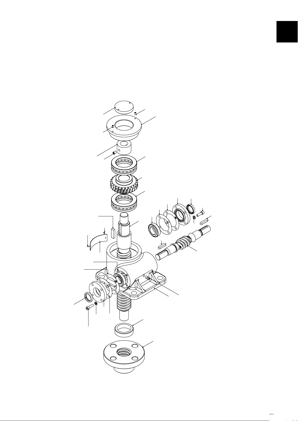
12.21 Rotating Inverted 25kN - 1000kN
8B
51A
51A
GeneralAssembly&PartsList
2H
12
58
57B
62
54B
6B
55
51D
61
59B*
62
10
57A
7C
3C
11C
6A
6A
6B
57B
53
57A
10
58
50C*
53
59B*
4
60
1
50C*
* 4 per side, except 1000kN which has 6 per side
5A
www.powerjacks.com 51
Page 52
Power Jacks are an industry leader in the manufacture of quality
industrial lifting, positioning,material handling and power transmission
equipment. The products are supplied globally to most industry
sectors including nuclear, water, oil & gas, chemical, defence, steel,
aluminium, automotive, and others.
PRECISION SCREW JACKS . ELECTRIC LINEAR ACTUATORS .
PLANETARY ROLLER SCREWS . SPIRAL BEVEL GEARBOXES .
DESIGN WITH POWER
Head Ofce
Balmacassie Commercial Park
Ellon
Aberdeenshire
AB41 8BX
Scotland (UK)
Manufactured in Great Britain
Tel: +44 (0)1358 285100
www.powerjacks.com
FM 23810
Supplied by Power Jacks. 2014 All rights reserved.
 Loading...