

Page 1
Installation &
Maintenance
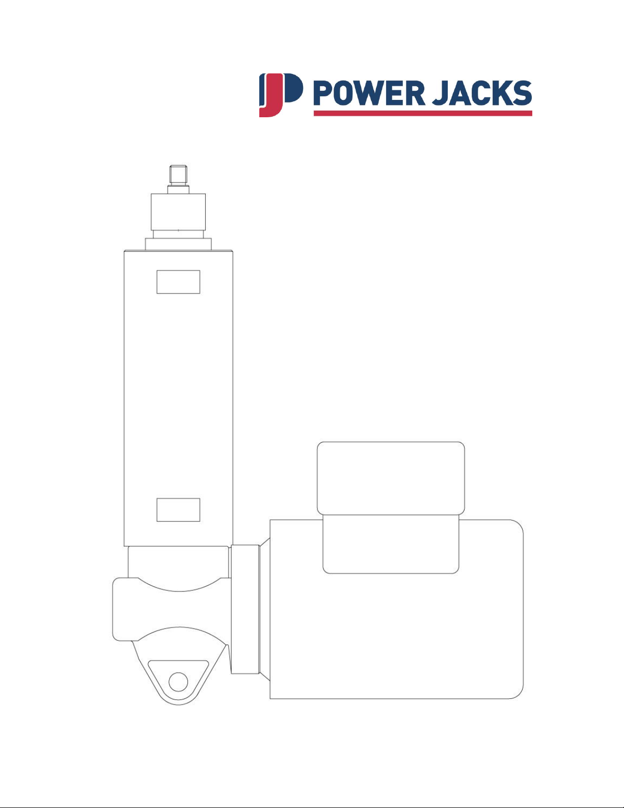
EMA
Electric Linear Actuators
Page 2

EMA Linear Actuator
2
Contents
1. SAFETY AUTHORISED USE ...................................................................................... 3
1.1 RESIDUAL RISK AND HAZARDS................................................................................... 3
1.2 OPERATING PERSONNEL .......................................................................................... 3
1.3 COMMISSIONING ...................................................................................................... 4
1.4 MODIFICATIONS AND ALTERATIONS TO THE UNIT ........................................................ 4
2. DESCRIPTION ............................................................................................................ 5
3. TECHNICAL DATA ..................................................................................................... 6
3.1 MODEL I - INTERMITTENT (LESS THAN 10 STARTS/DAY, 10 HOURS/DAY) ....................... 6
3.2 MODEL C - CONTINUOUS (MORE THAN 10 STARTS/DAY) ............................................. 6
3.3 MODEL H - HIGH SPEED CONTINUOUS ................................ ...................................... 6
4. MOUNTING A SINGLE ACTUATOR ........................................................................... 7
4.1 UNPACKING AND INSTALLATION ................................................................................ 7
4.2 MOUNTING .............................................................................................................. 7
4.3 MOUNTING OPTIONS ................................................................................................ 8
5. ADJUSTING THE LIMIT SWITCHES .......................................................................... 9
6. ADJUSTING THE CLUTCH ...................................................................................... 10
6.1 EMA CLUTCH GENERAL ASSEMBLY ........................................................................ 11
6.2 EMA CLUTCH SETTINGS ................................ ........................................................ 11
7. ELECTRICAL INSTALLATION ................................ .................................................. 12
7.1 LIMIT SWITCH – ELECTRO-MECHANICAL TYPE ......................................................... 12
7.2 MOUNTING THE DRIVE MOTOR ................................................................................ 12
7.3 STANDARD MOTOR TERMINAL BOX POSITION .......................................................... 13
7.4 OPTIONS ............................................................................................................... 13
7.5 MOTOR CONNECTION............................................................................................. 13
7.5.1 Three Phase Motor Connections ................................................................... 13
7.5.2 Single Phase Motor Connections .................................................................. 14
7.5.3 DC Motor ....................................................................................................... 14
8. MAINTENANCE AND LUBRICATION ....................................................................... 14
9. PARTS LIST - GENERAL .......................................................................................... 15
9.1 EMA ELECTRIC LINEAR ACTUATOR (GENERAL ASSEMBLY) ...................................... 16
Tel: +44 (0) 1358 285100 email: [email protected]
web: www.powerjacks.com
Page 3
EMA Linear Actuator
3
1. Safety Authorised use
EMA electric linear actuators are exclusively designed for carrying out lifting, lowering
and feeding movements with the lifting forces up to 10 kN. Any other application other
than specified or one going beyond the above mentioned capacity is unauthorised. The
manufacturer is not liable for damages resulting from such applications. The user alone
has to bear the risk.
Since the actuators can be applied in various areas, the user is responsible for the
specific application of use.
In compliance with the regulations concerning the electromagnetic compatibility of
machines, the EMA linear actuators may only be used in industrial areas according to
the definition EN 50 081-2.
Safety instructions in the operating manual
This symbol indicates potential dangers to people. Comply with
the instructions in order to avoid injury.
This symbol indicates potential dangers to the unit. Comply with
the instructions in order to avoid damage to the unit.
This symbol indicates special information on:
the best possible use of the unit
how to facilitate operation of the unit
1.1 Residual risk and hazards
Should a risk of damage to material or injury to persons remain despite the structural
safety of the EMA actuators, the user must employ other safety measures and draw
attention to such hazards by means of suitable warning notices and written instructions
indicating safety precautions.
1.2 Operating personnel
The EMA electric linear actuators are designed according to state-of-the-art technology
and are in line with applicable safety regulations.
Tel: +44 (0) 1358 285100 email: [email protected]
web: www.powerjacks.com
Page 4

EMA Linear Actuator
4
However, the general risks of personal injury or damage to property connected with the
use of such machinery cannot be completely eliminated. Therefore the units may only be
assembled and operated by competent and qualified personnel and only be used for the
authorised application. Therefore a careful study of this operating manual should be
made before attempting to use or service the unit and particular attention should be paid
to the safety instructions.
Work to be performed on electrical parts, such as:
installation of limit switches
mounting of the drive
Checking of the direction of rotation may only be carried out by qualified
electricians.
The linear actuators and the installation should be inspected by the operating and
supervising personnel for externally visible damage and defects at least once every shift.
Any changes (including the operational conditions) which may affect the safety are to be
reported immediately.
1.3 Commissioning
The EMA electric linear actuators must not be put into service before the machinery into
which it is to be incorporated fulfils all provisions of the EC directive relating to
machinery.
1.4 Modifications and alterations to the unit
It is not permitted to make any alterations to the safety features or design of the EMA
electric linear actuators without our written consent. Power Jacks declines any
responsibility in the event of such alterations. Worn and spare parts may only be
replaced after consultation with our service technicians or by them personally. It is not
permitted to disassemble or disconnect any safety or protection device. When using
special accessories the assembly instructions of the manufacturer must be observed!
The following regulations must be complied with:
the relevant regulations for the prevention of accidents
generally recognised safety regulations
EC guidelines and
National regulations
To comply with the regulations concerning the electromagnetic compatibility of
machines, the units must be connected according to EC rules & regulations. Therefore
the norms EN 50 081-2 and EN 50 082-2 should be observed, to avoid electromagnetic
interference.
Tel: +44 (0) 1358 285100 email: [email protected]
web: www.powerjacks.com
Page 5

EMA Linear Actuator
5
2. Description
EMA electric linear actuators are mainly used whenever precisely controlled lifting,
lowering or feeding movements are required. The actuators consist of either a
trapezoidal or ball lead screw, driven by an electric motor through spiroid gearing. The
screw converts the rotary motion into linear movement. As the screw rotates, the nut
extends and retracts the ram, which is attached to the load.
There are 3 standard EMA models, all available in a right-angle drive configuration.
Intermittent model, incorporating a trapezoidal screw.
Continuous model, incorporating a ball screw
High Speed Continuous model, incorporating a ball screw.
Where the standard range does not meet the application specification, special actuators
can be designed to meet customers’ specific requirements.
As standard, the units are available with 240V / 415VAC 3phase or 240VAC 1 phase or
24VDC motors, with or without a brake. The type of motors required is dependent on the
customer’s application. The motors are mounted to the actuator on an IEC 63C Face
Flange Mounting.
Tel: +44 (0) 1358 285100 email: [email protected]
web: www.powerjacks.com
Page 6
EMA Linear Actuator
6
Dynamic Load
Capacity (kN)
Linear Speed
(mm/min)
Motor (kW)
Frame Size
Motor
Frame Size
Motor
Poles
Max. Stroke (mm)
(in compression)
10
135
0.18
D63 6 750
5
200
0.18
D63 4 750
5
270
0.18
D63 6 750
5
410
0.18
D63 2 750
2.5
820
0.18
D63 2 750
Dynamic Load
Capacity (kN)
Linear Speed
(mm/min)
Motor (kW)
Frame Size
Motor Frame
Size
Motor
Poles
Max. Stroke (mm)
(in compression)
10
225
0.18
D63 6 900
10
335
0.18
D63 4 900
10
685
0.18
D63 2 900
5
1370
0.18
D63 2 1250
2.5
2740
0.18
D63 2 1500
Dynamic Load
Capacity (kN)
Linear Speed
(mm/min)
Motor (kW)
Frame Size
Motor Frame
Size
Motor
Poles
Max. Stroke (mm)
(in compression)
10
900
0.25
D71 6 900
10
1375
0.37
D71 2 900
10
2755
0.55
D71 2 900
5
1805
0.18
D71 6 1250
5
5510
0.37
D71 2 1250
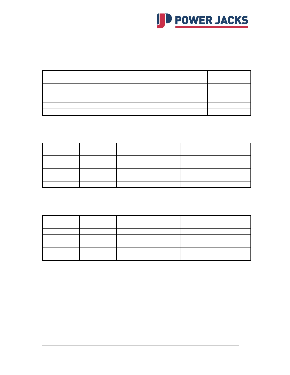
3. Technical Data
3.1 Model I - Intermittent (less than 10 starts/day, 10 hours/day)
3.2 Model C - Continuous (more than 10 starts/day)
3.3 Model H - High Speed Continuous
Tel: +44 (0) 1358 285100 email: [email protected]
web: www.powerjacks.com
Page 7

EMA Linear Actuator
7
4. Mounting a single actuator
4.1 Unpacking and Installation
Remove the EMA electric linear actuator from its container. Dispose of the packaging
material and the desiccant in an environmentally friendly way. If it is necessary and in
order to avoid damages, please use soft straps to transport or mount the actuator.
In order to avoid damage; do not attach the straps to the inner tube but to the
outer housing of the drive or to the gearbox.
4.2 Mounting
There are two possible ways of mounting the EMA actuator at the gearbox end:
By means of bearing journals for trunnion mounting or clevis mount.
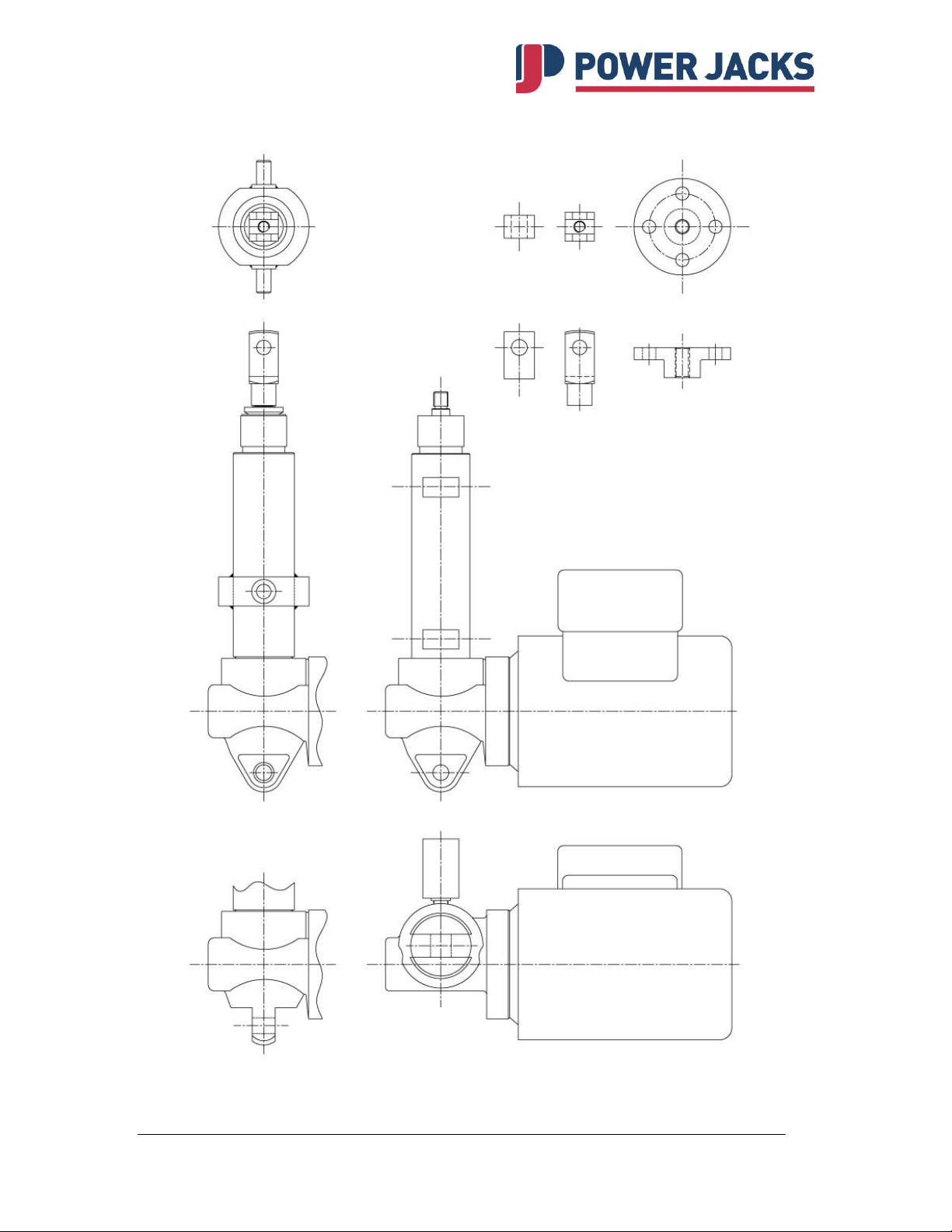
Rear Clevis
Mount the actuator by attaching the desired bracket and pin to the clevis end. Refer
to section 4.2.1 for ram mounting options.
Verify that the ram attachment is aligned throughout the actuator stroke before
connecting the ram. The ram attachment will either be pinned or bolted in place
depending on chosen model.
Trunnion Mount
Mount the actuator by attaching the desired bearings (or mounting feet) to the
trunnion pins. Refer to section 4.2.1 for ram mounting options.
Verify that the ram attachment is aligned throughout the actuator stroke before
connecting the ram. The ram attachment will either be pinned or bolted in place
depending on chosen model.
Always ensure that clevis holes align correctly and that they allow for the
correct angle of pivoting for the application before operating the actuator.
Side loads on the actuator ram should be avoided by ensuring that the
load is guided. The load guide mechanism should resist the torque
developed at the ram by the screw mechanism. A guided ram can be
supplied on request, which utilises a keyway in the inner ram, eliminates
the need for torsional restraint and therefore allows flexibility in the choice
of end fitting.
The desired mounting orientation will be determined when placing the order; this
orientation must be maintained at installation.
Tel: +44 (0) 1358 285100 email: [email protected]
web: www.powerjacks.com
Page 8
EMA Linear Actuator
8
Clevis
End
Fork
End
Threaded
End
Top Plate
Trunnion
Mount
Rear Clevis at 90°
Standard Rear Clevis
4.3 Mounting Options
Tel: +44 (0) 1358 285100 email: [email protected]
web: www.powerjacks.com
Page 9

EMA Linear Actuator
9
5. Adjusting the limit switches
Electrical connections may only be performed by licensed electricians.
Standard mechanical limit switches are used to cut off the electrical drive before the final
position is reached. The limit switch is triggered by a cam on the lifting nut assembly.
The positions of these limit switches are fixed and are not adjustable. The position is
determined by the length of stroke specified by order and cannot be changed at a later
date. The mounting of a position-measuring system is possible as an option.
Suitably rated mechanical safety limit switches must be used if the nondisconnection of the electrical drive constitutes a potential danger to
people.
Adjusting the best possible sensing distance:
1. Position the cam on the lifting nut assembly to cover the opening of the switch.
2. Screw the switch into the housing until the unit switches over.
3. Lock the switch in place with the lock nut.
4. Check the correct function of the switches by moving the lifting-nut assembly
manually.
5. If the switch works correctly then repeat the procedure for the next switch.
Otherwise repeat procedure for this switch.
6. Once all the limit switches are set ensure that the cam on the lifting nut is resting
in a position in between both end of travel limit switches.
The drive must not be put into service before all limit switches have been
mounted and correctly adjusted.
Tel: +44 (0) 1358 285100 email: [email protected]
web: www.powerjacks.com
Page 10

EMA Linear Actuator
10
6. Adjusting the Clutch
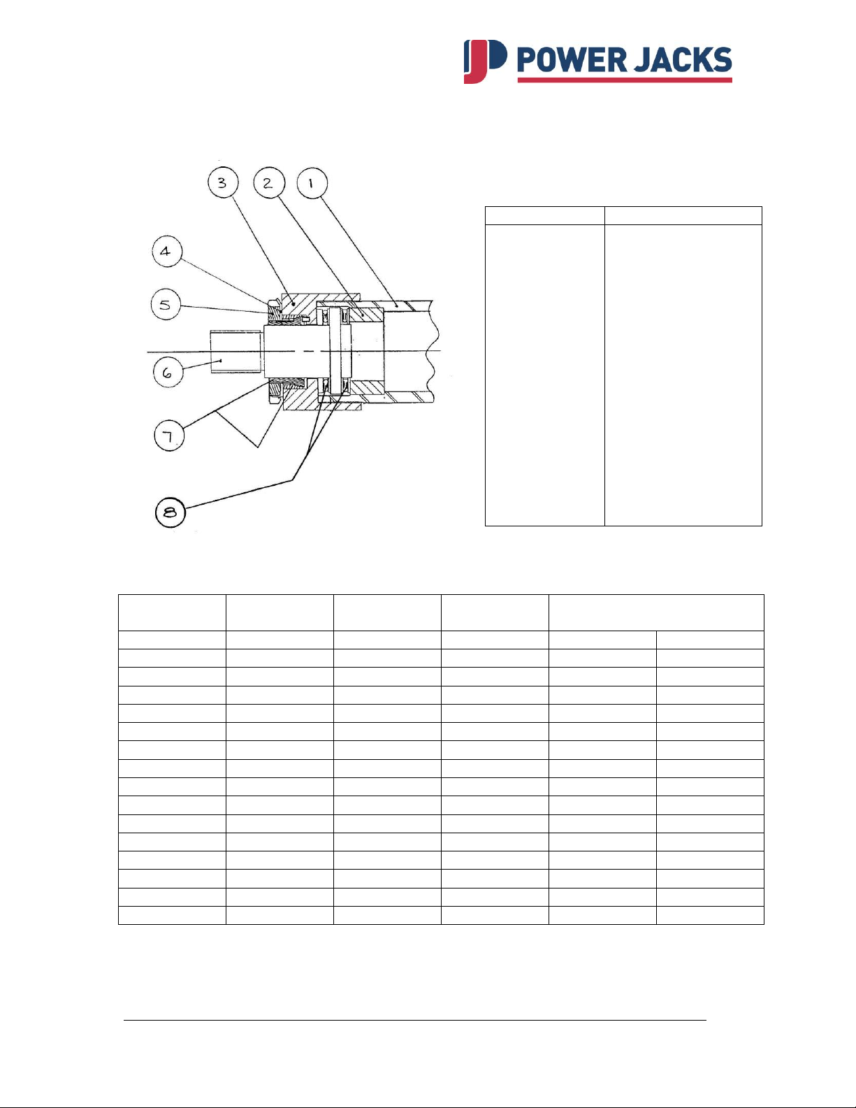
The clutch is a device mounted on the actuator inner tube (ram) which will slip when the
torque to drive the load exceeds the limit set. (refer 6.1)
The clutch spindle, (6) that is attached to the load via an end fitting, is supported on
bearings (8) and clamped from rotating by interlocking conical rings (7). The clamping
load is applied by a locknut (5) with keyways to engage a tab washer (4). The clutch
housing (3) is attached to the inner tube (1) and the clamping effort of the conical rings
(7) carries the residual torque of lifting to the clutch spindle (6).
If the load is axially locked or if a torque greater than the clutch setting is required to
move the load, the conical rings will rotate within each other, disengaging the spindle to
inner tube drive and preventing the motor from overloading the actuator components or
the load guides etc.
Under normal operation and with no overload experienced the clutch requires no regular
maintenance or adjustment. If however the clutch slips regularly in operation the setting
of the clutch will reduce to a point where the normal operating torque will overcome the
clutch and the load will not move. Under these circumstances the clutch can be adjusted
as follows:
1. Remove the actuator from the installation.
2. Extend the inner tube (1) and clamp in soft jaws in a vice.
3. Bend out the tab of the washer (4) from the keyway of locknut (5).
4. With a suitable fitting screwed on to the clutch spindle (6) tighten the locknut until
a torque is indicated in table 1 (refer 6.2) is measured, e.g. Clutch lever forces in
table are for a 254mm (10in) lever inserted through clevis.
5. When the torque has been set, bend a tab of the washer into an adjacent keyway
in the locknut. The actuator is ready to reinstall.
6. The clutch is selected from either of the following:
a) Ringspan Cone Clamping Element TLK 250:-
i) 4202015.001 - 27Nm max.
ii) 4202025.001 - 74Nm max.
7. When assembling the clutch a small quantity of oil (3 in 1) should be
applied to the cone (7) surfaces.
Tel: +44 (0) 1358 285100 email: [email protected]
web: www.powerjacks.com
Page 11
EMA Linear Actuator
11
Actuator
Rating
Lead
Type
Torque
Clutch Lever Force
(kg
(mm)
-
(Nm)
lbs
kg
250 3 T
7.8 7 3
250 5 B
4.9 4 2
250 6 T
15.6
14
6
250
10 B 9.8 9 4
250
12
T
31.2
28
13
250
20
B
19.5
17
8
250
25
B
24.4
22
10
500 3 T
15.6
14
6
500 5 B
9.8 9 4
500 6 T
31.2
28
13
500
10
B
19.5
17
8
500
12
T
62.4
55
25
500
20 B 39
35
16
500
25
B
48.8
43
20
1000 5 B
19.5
17
8
Item Number
Description
1
2
3
4
5
6
7
8
Inner Tube (ram)
Distance Piece
Clutch Housing
Tab Washer
Lock Nut
Clutch Spindle
Conical Rings
Thrust Bearing
6.1 EMA Clutch General Assembly
6.2 EMA Clutch Settings
Type:
T - Trapezoidal
B - Ball Screw
Tel: +44 (0) 1358 285100 email: [email protected]
web: www.powerjacks.com
Page 12
EMA Linear Actuator
12
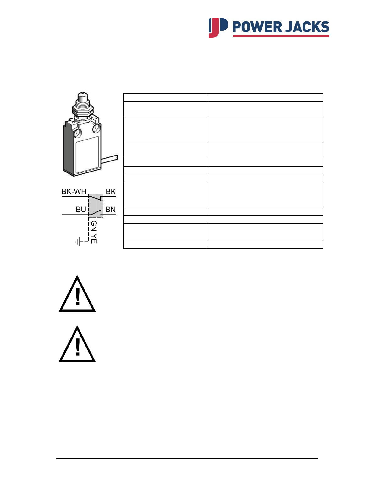
Item
Description
Housing
Metal, compact housing, totally
enclosed and sealed.
Pre-Cabled
2m PVC cable 5x0.75mm2 (other
cable lengths available on
request).
Switch type
Single-pole, 1 change-over, snap
action.
Switch Actuation
End of plunger (metal).
Max actuation speed
0.5 m/s
Mechanical durability
10 million operating cycles.
Ambient temperature
Operation
Storage
-25°C +70°C
-40°C +70°C
Product conformity
IEC947-5-1
Enclosure
IP67
Operating characteristics
AC-15; B300 (Ue=240V, Ie=1.5A)
DC-13; R300 (Ue=250V, Ie=0.1A)
Insulation voltage
Ui=300V
7. Electrical Installation
7.1 Limit Switch – Electro-Mechanical Type
7.2 Mounting the drive motor
The electrical installations and the checking of the direction of rotation
may only be carried out be a licensed electrician.
Connect the motor in compliance with the electro-technical regulation
Before mounting the motor, check the direction of rotation / linear travel of the EMA
actuator and the operation of the limit switches (if fitted). In order to do this:
1. Place the motor at the mounting position near the gearbox input.
2. Switch on the motor and check the direction of rotation.
3. Check the direction of rotation / linear travel by manually turning the gearbox input
shaft. Change the direction of the motor rotation if necessary by changing motor
connections.
4. Where necessary, attach coupling halves to motor shaft.
5. Mount motor onto gearbox input flange using screws provided.
Tel: +44 (0) 1358 285100 email: [email protected]
web: www.powerjacks.com
Page 13
EMA Linear Actuator
13
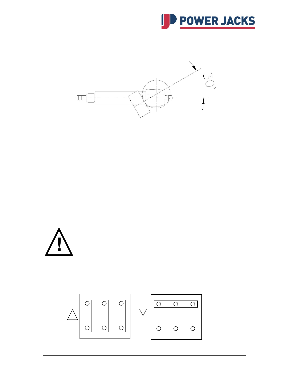
W2
U2
V2
U1
V1
W1
U1
V1
W1
W2
U2
V2
7.3 Standard Motor Terminal Box Position
7.4 Options
Delivery with mounted brake motor (DC or AC brake).
Delivery with non-standard motor types e.g. servo motor, 48VDC motor.
Special request, motor being supplied by the customer.
7.5 Motor Connection
The electrical connections for the standard three-phase, single-phase or DC-permanentmagnet motor are within the terminal box. Appropriate rated and insulated cables require
to be selected in accordance with the rated power. If motors are supplied with flying
leads please consult Power Jacks.
All electrical connections are to be carried out by a qualified electrician.
7.5.1 Three Phase Motor Connections
Star and Delta connections for dual wound motors
Tel: +44 (0) 1358 285100 email: [email protected]
web: www.powerjacks.com
Page 14
EMA Linear Actuator
14
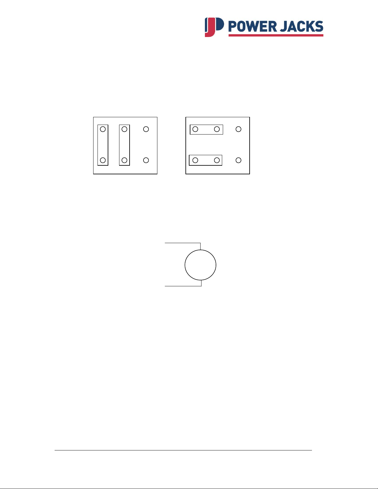
L1
L2
L1
L2
L1
L1
L2
L2
Forward
Reverse
Motor
+ve
-ve
7.5.2 Single Phase Motor Connections
This diagram is typical for motors with on board capacitors connected to the motor for
the correct start and run characteristics. For motors with loose capacitors consult Power
Jacks or the motor manufacturer.
7.5.3 DC Motor
8. Maintenance and Lubrication
Unless otherwise specified the actuators are shipped with their full requirement of
grease for normal operation. The actuators should not need a lubrication refill within their
standard life provided they have been installed and used correctly. Should the unit
require lubrication then use one of the following extreme pressure greases or their
equivalent:
Shell Alvania WR2
BP Energrease LC2
Castrol Spheerol L-EP2
Mobil Mobilux EP2
If ambient temperatures exceed 50°C (122°F) consult Power Jacks.
Tel: +44 (0) 1358 285100 email: [email protected]
web: www.powerjacks.com
Page 15

EMA Linear Actuator
15
Item
Description
1.
Gearbox housing
2.
Rear clevis guide bush.
3.
Pinnion bearing
4.
Pinnion
5.
Pinnion bearing
6.
Shims
7.
Thrust ring
8.
Circlip
9.
Grub screw for locking bearing cap.
10.
Shims
11.
Rear bearing for gear
12.
Grub screw for locking gear to lifting screw.
13.
Gear
14.
Front bearing for gear.
15.
Bearing end cap
16.
Lead screw (trapezoidal or ball screw).
17.
Emergency end stop pin
18.
Outer tube
19.
Guide bush for ram
20.
Seal/wiper unit for ram
21.
Lifting nut
22.
Grub screw for locking ram to lifting nut.
23.
Inner tube (ram)
24.
Clutch - Distance piece
25.
Clutch - Bearing washer (raceway)
26.
Clutch - Bearing cage assembly
27.
Clutch - Spindle
28.
Clutch - Housing
29.
Clutch - Ring Assembly (Lock nut, tab washer, conical ring)
30.
Ram end (clevis, fork end or top plate)
31.
Grub screw for locking ram end.
32.
Electric motor
33.
Trunnion Ring - Not shown on diagram (welded to outer
tube at customer specified point)
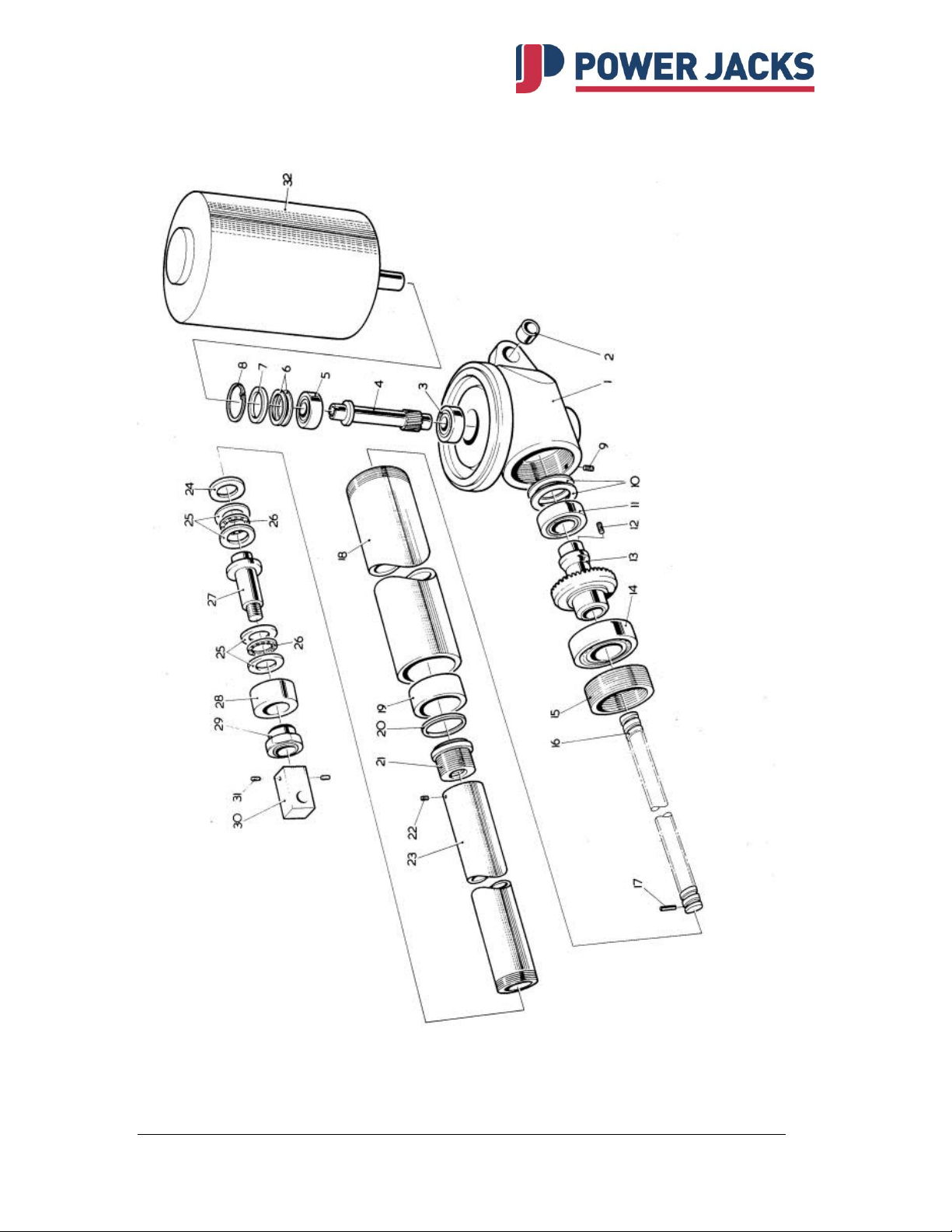
9. Parts List - General
(refer to section 9.1 for EMA Electric Linear Actuator general assembly diagram)
Tel: +44 (0) 1358 285100 email: [email protected]
web: www.powerjacks.com
Page 16
EMA Linear Actuator
16
9.1 EMA Electric Linear Actuator (General Assembly)
Tel: +44 (0) 1358 285100 email: [email protected]
web: www.powerjacks.com
Page 17

EMA Linear Actuator
17
Power Jacks Ltd
Balmacassie Commercial Park
Ellon AB41 8BX
Scotland
Tel: +44 (0) 1358 285100
Email: [email protected]
www.powerjacks.com
MM-LA-EMA-04-b
 Loading...