

Page 1

AN-1501
Application Note
Handling Instructions for SCALE™-1 and SCALE™-2 Gate
Drivers
Scope
This Application Note defines the requirements for handling the high-power SCALE™-1 and SCALE™-2
products (gate driver cores, plug-and-play gate drivers) from Power Integrations in terms of:
• Storage conditions
• Soldering instructions for gate driver core products
• Mechanical handling
• ESD handling
• Guideline for Return Material Analysis - RMA
The information given here applies to all customers, distributors a nd suppliers receiving high-power product s
from Power Integrations.
Content
Scope .............................................................................................................................................. 1
Content ........................................................................................................................................... 1
Storage Conditions ......................................................................................................................... 2
Soldering Instructions for Driver Core Products............................................................................ 3
Reflow Soldering.................................................................................................................. 3
Wave Soldering ................................................................................................................... 3
Selective Soldering ............................................................................................................... 3
Manual Soldering ................................................................................................................. 4
Mechanical Handling ...................................................................................................................... 4
Insertion of Gate Driver Cores into the Carrier PCB ................................................................. 4
ESD Handling .................................................................................................................................. 6
EPA (Electrostatic Protected Area) ......................................................................................... 6
Guideline for Return Material Analysis - RMA ................................................................................ 6
Legal Disclaimer ............................................................................................................................. 7
Manufacturer .................................................................................................................................. 7
Power Integrations Worldwide High Power Customer Support Locations .................................... 8
www.power.com/igbt-driver Page 1
Page 2

AN-1501
Material
Measures
Ambient
Ambient Conditions
Max. Storage
[Months]
Non-dry pack*1
Original packaging
Air
25°C ± 10°C /
24
Dry pack*2
Packed, evacuated,
ESD protection
Air
25°C ± 10°C / < 85%
36
Dry pack*3
Packed, evacuated,
ESD protection
Nitrogen
25°C ± 10°C / < 85%
>48
Application Note
Storage Conditions
Power Integrations products mentio ned in this Application Note must be stored and shipped according to the
environmental conditions specified in Table 1.
Atmosphere
desiccant*4,
Humidity Indicator Card
(HIC), sealed moisture
barrier bag,
desiccant,
Humidity Indicator Card
(HIC), sealed moisture
barrier bag,
[Temp. / RH]
10% - 45%
Table 1 Environmental conditions and lifetime during storage and transportation
*1
Legend:
Products must be processed before the end of the maximum storage time.
- Low-pollution atmosphere and packaging
*2
- Valid for single packed drivers
*3
- Valid for single packed trays and stored in a nitrogen atmosphere
*4
- Number of desiccant units to be calculated according to JEDEC Standard 033
Time
Processing after the expiring date can increase the risk of non-processability or malfunction.
If the original packaging is damaged, opened and not stored in the ambient conditions specified in Table 1,
the products must be processed within 168 hours.
www.power.com/igbt-driver Page 2
Page 3
AN-1501
Name
Leaded
Lead-Free
Flux
25 weight % rosin,
75 weight % isopropanol
25 weight % rosin,
75 weight % isopropanol
Solder alloy
Sn63Pb37
Sn96.5Ag3.0Cu0.5
Flux amount
The fluxing is determined as per the requirement of the board area and the
solder joint size.
Pot temperature
280…300°C
PCB top-side temperature
100…125°C
Nozzle dragging rate
2…8mm/s3
Point soldering time
3…5s4
Parameter
Leaded
Lead-Free
Flux
25 weight % rosin,
75 weight % isopropanol
25 weight % rosin,
75 weight % isopropanol
Solder alloy
Sn63Pb37
Sn96.5Ag3.0Cu0.5
Flux amount
Depending on the PCB size and assembly comp lexity, the flux is determined to
the bottom.
Pot temperature
250°C
255°C
Preheating rate
3…4K/s1
PCB top-side temperature
90…110°C2
Dipping/dwelling time
3…5s
Solder pot contact width
20mm
Cooling-down rate
5K/s
Application Note
Soldering Instructions for Driver Core Products
Power Integrations gate driver cores can be soldered with the following techniques, which are defined for
different process conditions.
Reflow Soldering
Reflow soldering of drivers is not permitted.
Wave Soldering
Selective Soldering
obtain maximum solder on the top side of the PCB with minimal flux residues on
1
…depending on the length of the wave soldering machine
2
…depending on the thermal mass and components on the board when it reaches the solder pot
3
…depending on the solder joint size
The solder nozzle should be selected depending on the surface area of the solder joint.
4
…depending on the size of the solder joint
www.power.com/igbt-driver Page 3
Page 4
AN-1501
Name
Leaded
Lead-Free
Solder iron temperature
320°C
340°C (SAC305)
Maximum solder time
3-4s
Transformer
Transformer
Application Note
Manual Soldering
It is recommended to use lead-free solder EF2210, SAC30 5 alloy. However, other solder types may also be
used.
Mechanical Handling
The correct handling of mechanical gate drivers is based on two fundamental principles:
1) No excessive mechanical force must be applied to transformers.
2) No excessive mechanical force causing bending (reflected to IPC-T-650) must be applied to PCBs.
The root causes of possible driver failure mentioned above may appear during mounting and later during
operation. If the carrier PCB on which the driver core is pla ced is large, there is a risk of driver PCB bending
referred to the carrier PCB. These phenomena can be seen during vibrations tests where momentary
displacement between driver core and carrier PCB can be observed. Therefore if significant vibrations are
foreseeable, it is necessary to mechanically stabilize the driver.
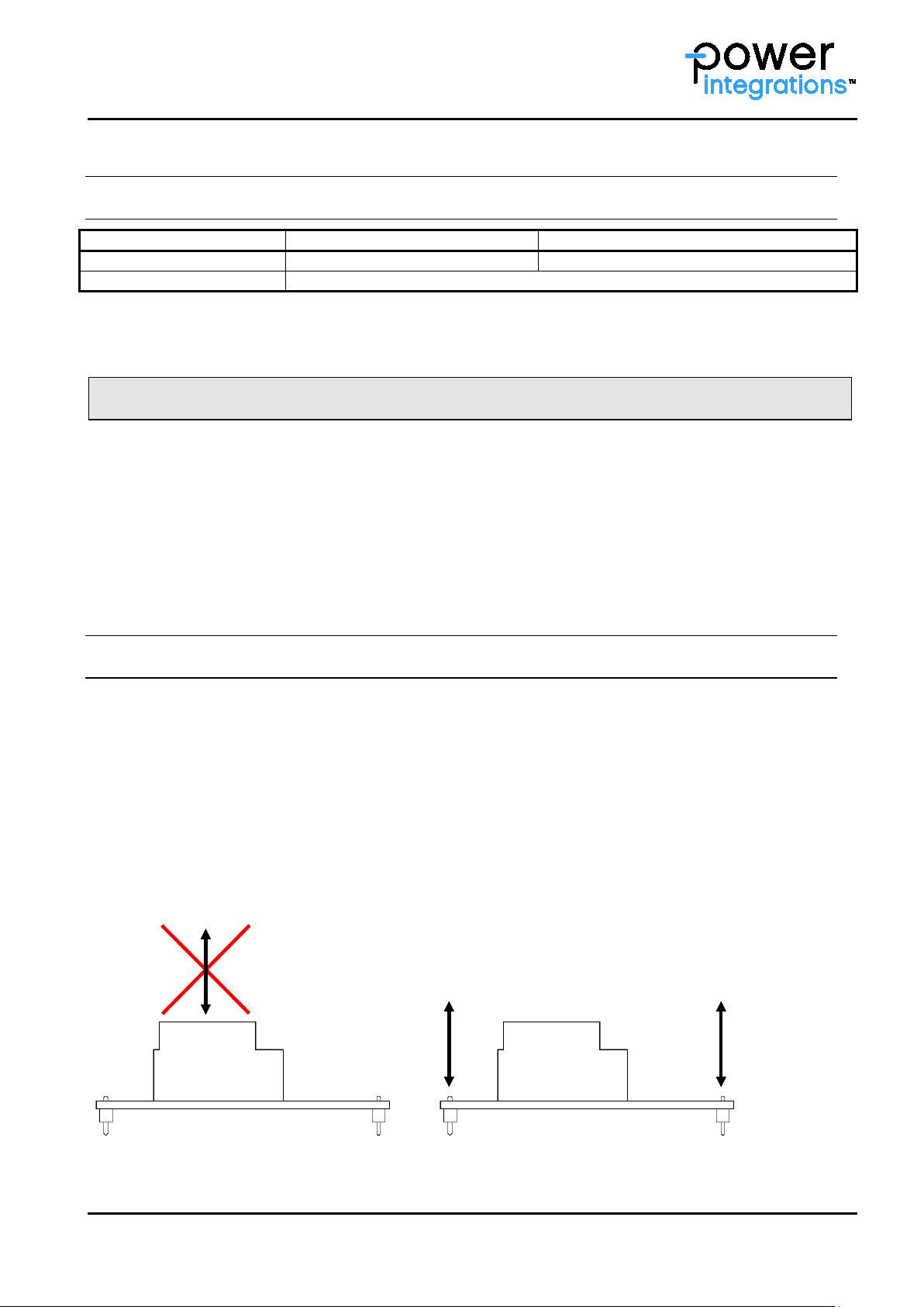
Insertion of Gate Driver Cores into the Carrier PCB
It is recommended that no large steady-state or temporary mechanical force be applied to the transformers or
terminals of the gate core drivers. Applying excessive mechanical force to the transformer bends the PCB and
considerably stresses the transformer solder joints, leading to potential pre-damage. This increases the
probability of cracks at the transformer solder points and other assembled SMD components, especially
ceramic capacitors and resistors.
The transformer may be held by hand during removal or insertion from/into the packaging or assembly to
carrier PCB, but the PCB should be free from bending.
Fig. 1 illustrates the correct removal and assembly of the driver core. If mechanical force applied to
transformer cause s PCB b ending or excessive mechanical stress to the solder join ts, the force must be shifted
directly to the corresponding terminals of the driver PCB.
Fig. 1 Not recommended (left) and recommended (right) ways of handling Power Integrations gate driver
cores during assembly (body plan of a driver)
www.power.com/igbt-driver Page 4
Page 5
AN-1501
PCB
IGBT Module
Distance
bolt
A
B
C
Application Note
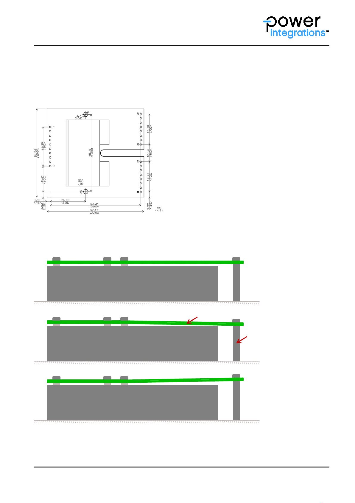
The IPC-T-650 standard gives general guidance for PCB handling and recommends that PCBs with surface
mount components are not exposed to bending or twisting o f more than 0.5% in relation to their length a nd
width. Fig. 2 s hows the gate driver core 2SC0435T as an example. It has dimension s (length and width) of
57.15mm by 51.56mm. The maximum permissible bending due to forces applied to the PCB would be 0.29mm
and 0.26mm respectively.
Fig. 2 Dimensions of a standard Power Integrations gate driver core
In case of Plug-and-Play drivers which are screw-fitted to a powe r module, it is important to adjust the height
of the distance bolts properly. This will increase the driver’s vibration withstand capability and avoid PCB
bending. Fig. 3 illustrates the corr ect usage of the bolts.
Fig. 3 Correct (A) and wrong (B and C) fixing of Power Integrations gate drivers
www.power.com/igbt-driver Page 5
Page 6

AN-1501
Application Note
ESD Handling
EPA (Electrostatic Protected Area)
In order to ensure a safe ESD environment in w hich the work on electronics c omponents or subassemblies
such as printed circuit boards is carried out, an ESD protected area or EPA must be set up and correctly used
every time Power Integrations’ high-power SCALE™-1 and SCALE™-2 product s are handled or processed. An
EPA or ESD PA (ESD Protected Area) is designed to minimize the generation and retention of ESD. It allows
the level of failures during production and later in life to be kept to a minimum.
Guideline for Return Material Analysis - RMA
The following requirements are necessary to ensure proper RMA process handling:
• Acquire RMA number from the Powe r Integrations Customer Service Department before return.
• For each RMA case, a “Driver Failure Description Form DFDF” must be compl eted.
• In the customs documents, a goods value of 1 USD must be specified.
• Returned product must be packed properly and according to ESD rules.
Note that the RMA process is not applicable to:
Prototypes (PRT) and Engineering (ENG) samples
Products that were used or operated beyond specification
Products arrived at customers with transportation damages
Products which arrive at Power Integrations without “Driver Failure Description Form DFDF”
Products without ESD-compliant packaging
www.power.com/igbt-driver Page 6
Page 7

AN-1501
Application Note
Legal Disclaimer
The statements, technical information and recommendations contained herein are believed to be accurate as
of the date hereof. All parameters, numbers, values and other technical data included in the technical
information were calculated and determined to our best knowledge in accordance with the relevant technical
norms (if any). They may base on assumptions or operational conditions that do not necessarily apply in
general. We exclude any representation or warranty, express or implied, in relation to the accuracy or
completeness of the statements, technical information and recommendations contained herein. No
responsibility is accepted for the accuracy or sufficiency of any of the statements, technical information,
recommendations or opini ons communicated and any liab ility for any direct, indirect or consequentia l loss or
damage suffered by any person arising therefrom is expressly disclaimed.
Manufacturer
Power Integrations Switzerland GmbH
Johann-Renfer-Strasse 15
2504 Biel-Bienne, Switz er la nd
Phone +41 32 344 47 47
Fax +41 32 344 47 40
Email igbt-driver.sales@power.com
Website www.power.com/igbt-driver
2015 Power Integrat ions Switzerland GmbH. All rights reserved.
We reserve the right to make any technical modifications without prior notice. Version 1.0 from 2016-04-14
www.power.com/igbt-driver Page 7
Page 8

AN-1501
World Headquarters
China (Shenzhen)
Japan (Kanagawa)
Application Note
Power Integrations Worldwide High Power Customer Support Locations
5245 Hellyer Avenue
San Jose, CA 95138 | USA
Main +1 408 414 9200
Customer Service:
Phone +1 408 414 9665
Fax +1 408 414 9765
Email usasales@power.com
Switzerland (Biel)
Johann-Renfer-Strasse 15
2504 Biel-Bienne | Switzerland
Phone +41 32 344 47 47
Fax +41 32 344 47 40
Email igbt-driver.sales@power.com
Germany (Ense)
HellwegForum 1
59469 Ense | Germany
Phone +49 2938 643 9990
Email
igbt-driver.sales@power.com
China (Shanghai)
Rm 2410, Charity Plaza, No. 88
North Caoxi Road
Shanghai, PRC 200030
Phone +86 21 6354 6323
Fax +86 21 6354 6325
Email chinasales@power.com
17/F, Hivac Building, No 2 ,
Keji South 8th Road,
Nanshan District
Shenzhen | China, 518057
Phone +86 755 8672 8725
Fax +86 755 8672 8690
Hotline +86 400 0755 669
Email chinasales@power.com
UK (Cambridge)
Westbrook Centre, Block 5,
2nd Floor Milton Road
Cambridge CB4 1YG
Phone: +44 (0) 1223-446483
Email: eurosales@power.com
India (Bangalore)
#1, 14th Main Road
Vasanthanagar
Bangalore 560052 | India
Phone +91 80 4113 8020
Fax +91 80 4113 8023
Email indiasales@power.com
Kosei Dai-3 Bldg., 2-12-11, ShinYokohama, Kohoku-ku, Yokohama-shi,
Kanagawa 222-0033 | Japan
Phone +81 45 471 1021
Fax +81 45 471 3717
Email japansales@power.com
Korea (Seoul)
RM 602, 6FL
Korea City Air Terminal B/D, 159-6
Samsung-Dong, Kangnam-Gu
Seoul 135-728 | Korea
Phone +82 2 2016 6610
Fax +82 2 2016 6630
Email koreasales@power.com
Taiwan (Taipei)
5F, No. 318, Nei Hu Rd., Sec. 1
Nei Hu Dist.
Taipei 11493 | Taiwan R.O.C.
Phone +886 2 2659 4570
Fax +886 2 2659 4550
Email taiwansales@power.com
www.power.com/igbt-driver Page 8
 Loading...