

Power Innovations INTegral Line 650 VA User Manual
Line-Interactive
Uninterruptible Power Supply Unit
650 VA
INTegral Line-Interactive Uninterruptible Power Supply Unit—650 VA Power Innovations 1
USER’S MANUAL
MNL105-650VA-T

READ THIS MANUAL CAREFULLY
SAVE ALL INSTRUCTIONS
This manual contains important information that you will need to operate the UPS safely and efficiently. Please read all
instructions carefully before installing or operating equipment.
Keep this manual handy for easy reference.
ELECTRICAL WARNINGS
Read and follow installation instructions carefully before operating.
Applying information contained in this manual to any other product may cause injury.
The INTegral is registered for sale by Power Innovations International, Inc.
This manual may have been received with other products or instructional materials. If additional products or instructional
materials have been ordered but have not been received, contact your reseller.
© Copyright 2015
Power Innovations International, Inc.; American, Fork, UT, USA. All rights reserved.
The Standard for Perfect, Dependable Power
Version 1.0
2 Power Innovations INTegral Line-Interactive Uninterruptible Power Supply—650 VA

Table of Contents
1.1—Congratulations on Your Purchase ................................................................................................................................ 4
1.1.1—Key Features ............................................................................................................................................................ 4
1.2—Using this Manual ........................................................................................................................................................... 5
1.2.1—Manual Conventions ................................................................................................................................................ 5
1.2.1.1—Additional Advice ............................................................................................................................................... 5
1.2.1.2—Type Conventions ............................................................................................................................................. 5
1.3—Power Flow ..................................................................................................................................................................... 6
1.3.1—Normal Power Mode ................................................................................................................................................ 6
1.3.2—Battery Backup Mode ............................................................................................................................................... 7
2.1—Receiving ........................................................................................................................................................................ 8
2.2—Transporting ................................................................................................................................................................... 8
3.1—Placing Systems Correctly .............................................................................................................................................. 9
3.1.1—Environmental Concerns.......................................................................................................................................... 9
3.1.2—System Ventilation ................................................................................................................................................. 10
3.1.3—Orienting the System Correctly .............................................................................................................................. 10
3.2—Connecting Systems ..................................................................................................................................................... 10
4.1—System Power-ON ........................................................................................................................................................ 13
4.2—Cold Start ...................................................................................................................................................................... 14
4.3—Running on Battery Power............................................................................................................................................ 14
4.4—No Outputs Connected ................................................................................................................................................. 14
4.5—System Power OFF ...................................................................................................................................................... 14
4.5.1—While Connected to Input....................................................................................................................................... 14
4.5.2—While in Battery (Backup) Mode ............................................................................................................................ 14
4.6—Storing the System ....................................................................................................................................................... 14
5.1—Maintenance ................................................................................................................................................................. 16
5.2—Troubleshooting Tables ................................................................................................................................................ 16
5.2.1—Utility Power Functioning ....................................................................................................................................... 16
5.2.2—Utility Power Failing ............................................................................................................................................... 17
7.1—Limited Warranty .......................................................................................................................................................... 20
7.1.1—Shipment and Power-up Dates .............................................................................................................................. 20
7.1.2—Warranty Inclusions ............................................................................................................................................... 20
7.2—Part Replacement and Servicing .................................................................................................................................. 20
7.2.1—Restrictions ............................................................................................................................................................ 20
7.2.1.1—Unauthorized Service or Removed Serial Number ......................................................................................... 20
7.2.1.2—Product Misuse or Abuse ................................................................................................................................ 20
7.2.2—Legal Rights ........................................................................................................................................................... 20
7.2.3—Limitations of Coverage ......................................................................................................................................... 20
7.2.4—Proof of Purchase .................................................................................................................................................. 21
7.3—Warranty Claims ........................................................................................................................................................... 21
7.3.1—On-site Visits .......................................................................................................................................................... 21
7.3.2—Product Shipping .................................................................................................................................................... 21
7.3.2.1—Prior Approval .................................................................................................................................................. 21
7.4—Limitation of Remedies ................................................................................................................................................. 21
8.1—Information to Provide .................................................................................................................................................. 22
8.2—Returning Equipment .................................................................................................................................................... 22
8.3—Replacement Assemblies ............................................................................................................................................. 22
INTegral Line-Interactive Uninterruptible Power Supply Unit—650 VA Power Innovations 3
1—Introduction
1.1—Congratulations on Your Purchase
Thank you for purchasing Power Innovations’ INTegral Line-Interactive Power Supply Unit. Power Innovations believes in
the efficiency and durability of its products. The company hopes that this product will serve you well for an extended
period of time.
Office equipment needs reliable, clean power. The Uninterruptible Power System (UPS) is designed to meet all computer,
server and automated office equipment needs with a compact, quiet unit that operates efficiently and provides multiple
interface options.
To choose the INTegral 650LED as your equipment protector is a wise investment because it supplies reliable, pure and
stable power at an affordable price.
1.1.1—Key Features
Line-interactive sine-wave topology
Intelligent charger
Compact size
Intelligent fan speed control
Battery cold start
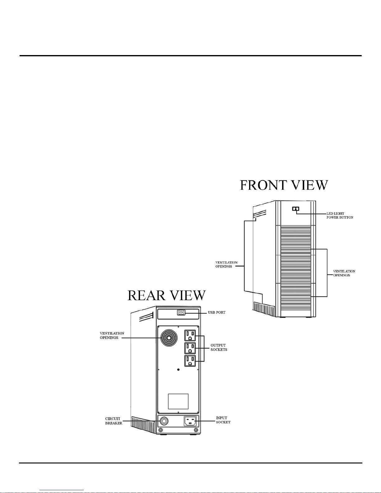
Figures 1 and 2: Front and Rear Features of the 650 kVA INTegral System
4 Power Innovations INTegral Line-Interactive Uninterruptible Power Supply—650 VA
1.2—Using this Manual
Read and understand this manual to make installing and operating the system as easy as possible.
This manual will show how to safely work the INTegral. Refer to the
Table of Contents
1.2.1—Manual Conventions
1.2.1.1—ADDITIONAL ADVICE
This manual will occasionally provide additional advice. When it is provided, this information will be enclosed by a
set of lines to separate it from the rest of the text, like this:
This text does not belong with the rest.
Some of the information is very important, while other information may be good to know. To show the importance
of each piece of information, the following symbols and formatting conventions are used:
WARNINGS
Denotes advice that, if not followed, could cause severe bodily harm or death due to
electrical shock.
Denotes advice that, if not followed, could cause severe bodily harm or death due to other
types of injury.
Cautions
Offers advice that, if not followed, may harm equipment or indirectly cause physical hazards.
Notes
Offers practical advice that may be helpful, but can be disregarded.
1.2.1.2—TYPE CONVENTIONS
Italic type—Used for some product acronyms
Bold type
Other noteworthy type conventions used in this manual include:
INTegral Line-Interactive Uninterruptible Power Supply Unit—650 VA Power Innovations 5
—Used to caption figures
for a chapter-based guide.
Italic type—Used to refer readers to another chapter or section.
Bold type
—Used to reference figures included on the same or following pages.
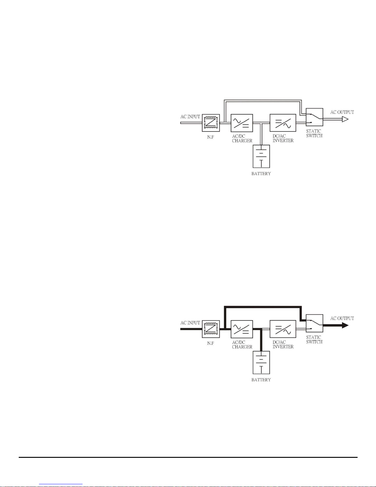
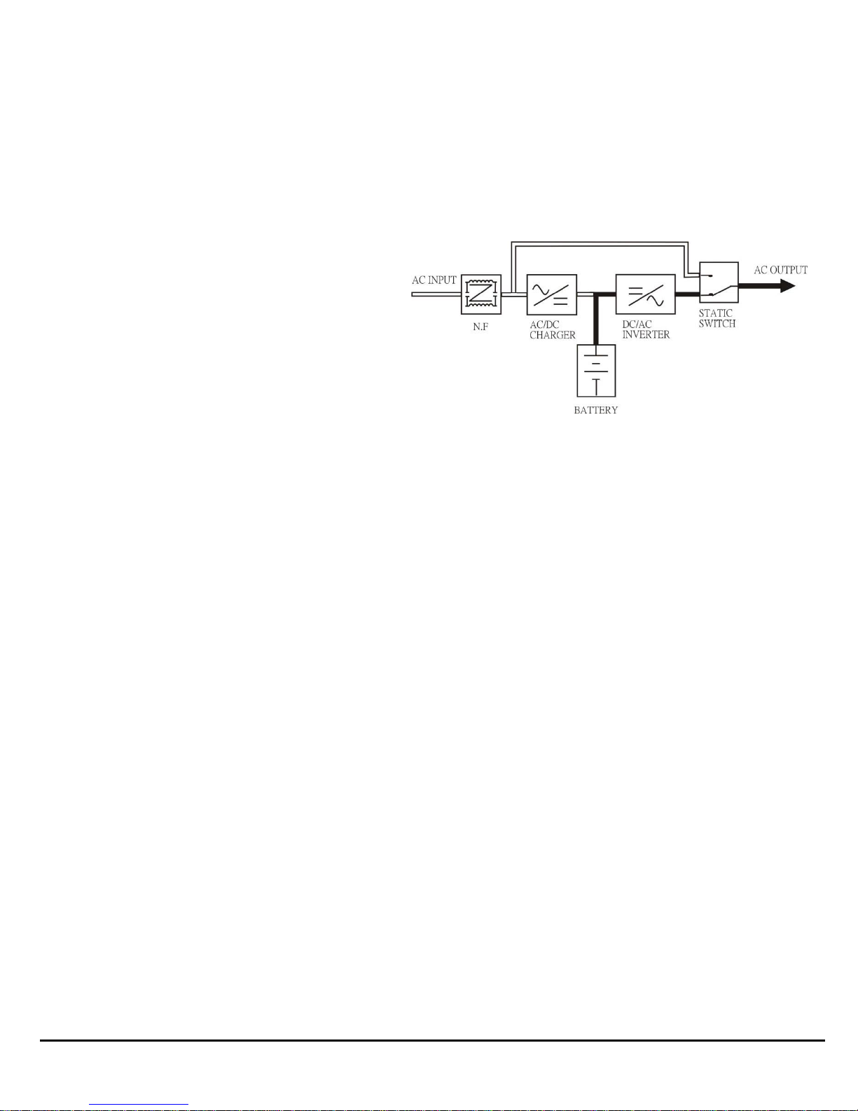
1.3—Power Flow
In the INTegral Line-Interactive UPS System, AC utility power flows through two main loops: the AC loop and the battery
charging loop (
Figure 3: Power Flow for INTegral Line-interactive system
Figure 3
1.3.1—Normal Power Mode
When functioning normally, the system will power the load and charge batteries to operate when utility power is
unstable. This method of battery backup provides a cost-effective means of providing reliable, uninterruptible power
and increasing UPS efficiency to save you money.
In the AC loop, the power comes from AC utility input such as a wall outlet and passes through a static switch to
support power to the load so long as power is clean and reliable
In the battery charging loop, an AC/DC converter changes AC utility input voltage into DC power, which charges the
system’s batteries.
Figure 4: Power flow during Normal Power Mode
).
(Figure 4)
.
6 Power Innovations INTegral Line-Interactive Uninterruptible Power Supply—650 VA
1.3.2—Battery Backup Mode
In this mode, AC output comes from the battery. Battery voltage is boosted and converted to create a clean, stable
AC sine wave to power even the most sensitive equipment.
Power will pass from the battery through the DC/DC converter, DC/AC inverter, and static switch to provide output for
the full length of the battery charge. Actual battery backup time will vary, depending upon initial battery charge and
the current load percentage. See
Figure 5: Power flow during Battery Backup Mode
6—Specifications
for backup time estimates.
INTegral Line-Interactive Uninterruptible Power Supply Unit—650 VA Power Innovations 7
 Loading...