

Line-Interactive Uninterruptible
Power Supply Unit
2kVATower Model (203T)
USER’S MANUAL
MNL105-203T
Version 1.0
Powering Life

READ THIS MANUAL CAREFULLY
SAVE ALL INSTRUCTIONS
This manual contains important information that you will need to operate the UPS safely and efficiently. Please read all
instructions carefully before installing or operating equipment.
Keep this manual handy for easy reference.
Caution
Read installation instructions carefully before operating.
Follow all instructions, warnings, and cautions listed in this manual. Failure to do so may cause injury
or product damage not covered by the warranty.
Applying information contained in this manual to any other product may cause injury.
The INTegral is registered for sale by Power Innovations International, Inc.
Version 1.0
© Copyright 2015.
All rights reserved.
Power Innovations: Powering Life
Power Innovations International, Inc.
American Fork, UT, USA

Table of Contents
1.1—Key Features .................................................................................................................................................................. 1
Standard Features ........................................................................................................................................................... 1
Additional Features .......................................................................................................................................................... 1
2.1—Using this Manual ........................................................................................................................................................... 2
2.2.1—Additional Advice ..................................................................................................................................................... 2
2.2.2—Type Conventions .................................................................................................................................................... 2
2.3—Power Flow ..................................................................................................................................................................... 3
2.3.1—Normal Power Mode ................................................................................................................................................ 3
2.3.2—Battery Backup Mode ............................................................................................................................................... 4
2.1—Receiving ........................................................................................................................................................................ 5
2.2—Transporting ................................................................................................................................................................... 5
3.1—Selecting an Operating Environment .............................................................................................................................. 7
3.2—Placing by Configuration Type ....................................................................................................................................... 7
3.3—Connecting Units ............................................................................................................................................................ 8
3.4—Prestart Checklist ........................................................................................................................................................... 9
4.1—Operating Cautions ....................................................................................................................................................... 11
4.2—Keys and Indicators ...................................................................................................................................................... 12
4.2.1—Basic Operations .................................................................................................................................................... 13
4.3—Information about Operations ....................................................................................................................................... 13
4.4—Navigating the Menus ................................................................................................................................................... 13
4.5—RS-232 Computer Interface Port .................................................................................................................................. 16
4.5.1—DB9 Pin Assignment .............................................................................................................................................. 16
4.6—Protecting a Fax Machine or Modem ........................................................................................................................... 17
4.7—Remote Control Display ................................................................................................................................................ 17
4.8—Emergency Power OFF ................................................................................................................................................ 17
4.9—Storing the System ....................................................................................................................................................... 18
5.1—Maintenance ................................................................................................................................................................ 19
5.2—Troubleshooting ............................................................................................................................................................ 19
5.2.1—Utility Power Functioning ....................................................................................................................................... 19
5.2.2—Utility Power Failing ............................................................................................................................................... 20
7.1—No Battery Maintenance ............................................................................................................................................... 23
7.2—Storage Concerns ......................................................................................................................................................... 23
8.1—Limited Warranty .......................................................................................................................................................... 25
8.1.1—Rights Under This Warranty .................................................................................................................................. 25
8.1.2—Part and Product Coverage ................................................................................................................................... 25
8.1.3—Restrictions ............................................................................................................................................................ 25
8.1.3.1—Previous Service ............................................................................................................................................. 25
8.1.3.2—Misuse or Abuse.............................................................................................................................................. 25
8.1.3.3—Non-Transferable ............................................................................................................................................ 25
8.2—Warranty Claims ........................................................................................................................................................... 26
8.2.1—Proof of Purchase .................................................................................................................................................. 26
8.2.2—Notifying Power Innovations .................................................................................................................................. 26
8.2.3—Product Shipping .................................................................................................................................................... 26
8.24—Prior Approval ......................................................................................................................................................... 26
8.3—Limitation of Remedies ................................................................................................................................................. 26
8.3.1—Indirect Damages ................................................................................................................................................... 26
8.4—Customer Service ......................................................................................................................................................... 26
INTegral Line-Interactive Uninterruptible Power Supply Unit—2kVA-T Power Innovations i

This page intentionally left blank.
1—Introduction
The INTegral Uninterruptible Power Supply Unit (UPS) is a compact backup unit that supplies clean, reliable power
essential for operating equipment. Even when utility power fails, this system will supply backup power for three (3)
minutes or more at full load (see 6—Specifications).
1.1—Key Features
STANDARD FEATURES
Line-interactive sine wave topology
Intelligent charger
Compact size
Intelligent fan speed control
Cold Start
It is possible to have one (1) additional feature included on the INTegral, while others are not
included.
INTegral Line-Interactive Uninterruptible Power Supply Unit—2kVA-T Power Innovations 1
ADDITIONAL FEATURES
Multiple interface options
Detachable dot-matrix LCD panel
Note
2.1—Using this Manual
Read and understand this manual to make installing and operating the unit as easy as possible.
This manual will show how to safely work the INTegral Line-Interactive UPS. Refer to the Table of Contents for a chapter-
based guide.
2.2—Manual Conventions
2.2.1—Additional Advice
This manual will occasionally provide additional advice. When it is provided, this information will be enclosed by a
set of lines to separate it from the rest of the text, like this:
This text does not belong with the rest.
Some of the information is very important, while other information may be good to know. To show the importance
of each piece of information, the following symbols and formatting conventions are used:
WARNINGS
ELECTRICAL: Denote advice that, if not followed, could cause severe bodily harm or death
due to electrical shock.
GENERAL: Denote advice that, if not followed, could cause severe bodily harm or death due
to other types of injury.
Cautions
Offer advice that, if not followed, may harm equipment or indirectly cause physical hazards.
Notes
Offer practical advice that may be helpful, but can be disregarded.
2.2.2—Type Conventions
Italic type—Used for some product acronyms and for the name of the product itself.
Bold type—Used to reference figures or other chapters or sections.
Blue, Underlined type—Used for PDF viewing. The inclusive text is a hyperlink to be accessed by pressing the
control button (CTRL) and clicking on the text.
2 Power Innovations INTegral Line-Interactive Uninterruptible Power Supply—2kVA-T
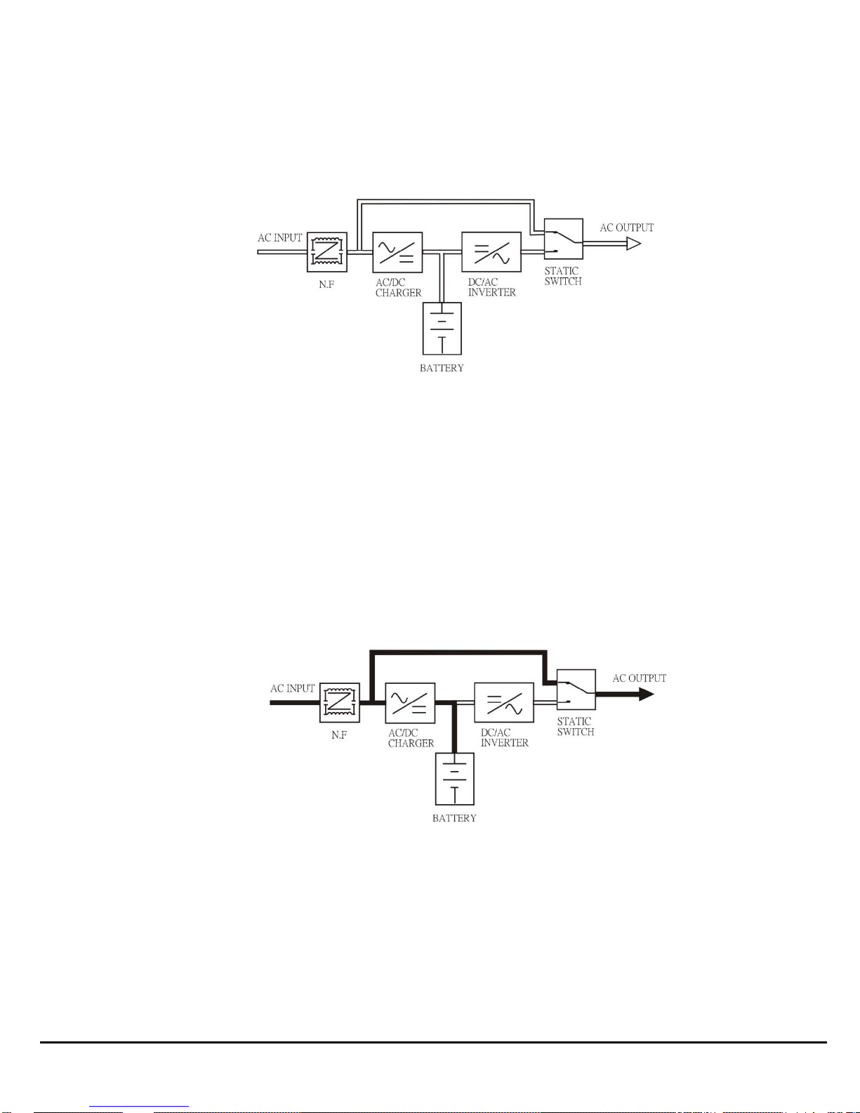
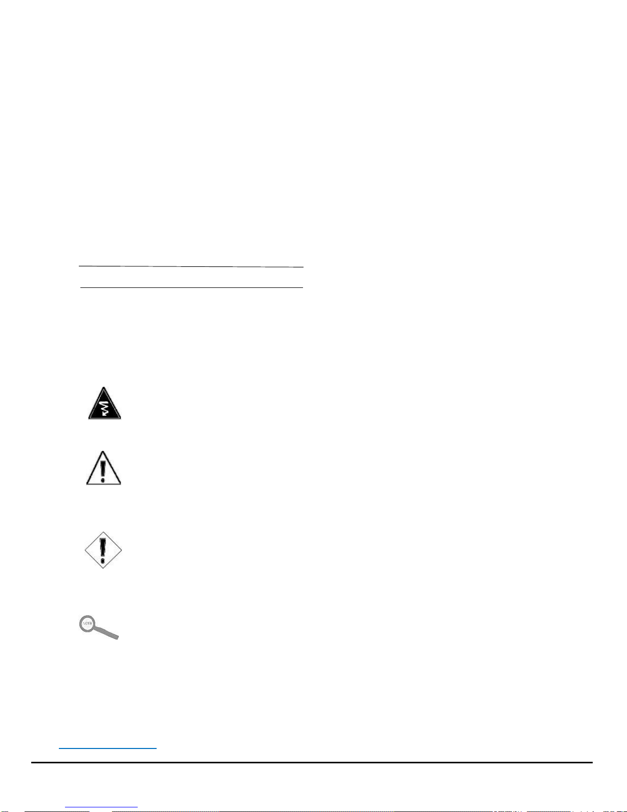
Figure 1: UPS Power Flow Diagram
Figure 2: Power Flow in Normal Mode
2.3—Power Flow
In the INTegral Line-Interactive UPS, AC utility power flows through two (2) main loops: the AC loop and the battery
charging loop (Figure 1).
2.3.1—Normal Power Mode
When functioning normally, the system will charge batteries to operate when utility power is unstable. Battery
charging from the utility supply provides a cost-effective means of providing reliable, uninterruptible power and
increasing UPS efficiency—saving you money.
In the AC loop, the power comes from AC utility input such as a wall outlet and passes through a static switch to
support power to the load, so long as power is clean and reliable.
In the battery charging loop (Figure 2), an AC/DC converter changes AC utility input voltage into DC power, which
charges the unit’s batteries.
INTegral Line-Interactive Uninterruptible Power Supply Unit—2kVA-T Power Innovations 3
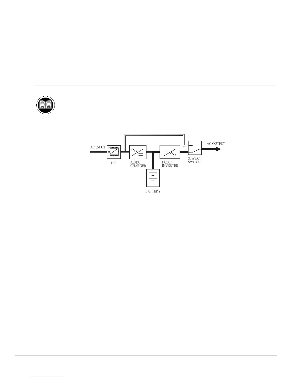
Figure 3: Power Flow in Battery Backup Mode
2.3.2—Battery Backup Mode
In Battery Backup Mode, the AC output come from the battery. Battery voltage is boosted and converted to create a
clean, stable AC sine wave to power even the most sensitive equipment.
Power will pass from the battery through the DC/DC converter, DC/AC interver, and static switch to provide output for
the full length of the battery charge.
Actual backup time will vary, depending upon initial battery charge and current load percentage.
Manual Helps
See 6—Specifications for backup time estimates.
4 Power Innovations INTegral Line-Interactive Uninterruptible Power Supply—2kVA-T

2—Receiving and Transporting Systems
Because the UPS supplies power, it must be handled carefully. For better product performance and to avoid injury, follow
the guidelines below.
2.1—Receiving
Inspect the packaging carton and its contents for damage. If the contents have been damaged, notify your reseller
immediately.
After removing the system, keep its packaging in a safe place for future use.
Caution
It would be best not to discard packaging materials, since it is recommended that the unit be
packaged in its original packaging for future shipping and transport.
2.2—Transporting
Disconnect all power cables and power down the unit before moving it.
While moving the unit, handle it carefully. The combined weight of the unit and its batteries can be significant.
It is recommended that the system be transported only in the original packaging.
ELECTRICAL WARNING
Do not transport the unit while power cables are attached. Failure to heed this warning could
cause accidental injury or death from electrical shock.
Cautions
Save the original packaging and use it for transport. Using the correct packaging will prevent
unnecessary harm to the unit.
Note
With concerns about the manufacture or shipping of this product or its components, please contact:
Power Innovations International, Inc.
Tel: (801) 785-4123 Fax: (801) 785-6999
E-mail: service@power-innovations.com
INTegral Line-Interactive Uninterruptible Power Supply Unit—2kVA-T Power Innovations 5

This page intentionally left blank.

3—Installing Units
3.1—Selecting an Operating Environment
To avoid damage or accidental injury, place the unit right-side up in a clean, dry location far from environmental
contaminants and heat sources.
Never place this unit:
Upside down or on an incline.
In direct sunlight or weather.
Near any source of natural or artificial heat.
With less than 1” of ventilation space on all sides
with visible ventilation holes.
Avoid locations where the unit:
Could be exposed to flammable gases or
corrosive liquids.
Will be cooler than 32°F (0°C) or hotter than 104°F (50°C).
Will be exposed to clutter or objects that could block ventilation openings.
Cannot ventilate.
Caution
Not following the placing recommendations listed above could lead to system overheating or injury.
3.2—Placing by Configuration Type
Each unit is designed to operate in one of three configurations: exclusively as a tower unit, as a convertible unit (operates
either as a tower or rack mount), or exclusively as a rack mount unit.
Since the letter following this model number is a T, this model is meant to operate exclusively in tower configuration. To
correctly place a tower unit, set it on its vertical bottom end.
INTegral Line-Interactive Uninterruptible Power Supply Unit—2kVA-T Power Innovations 7

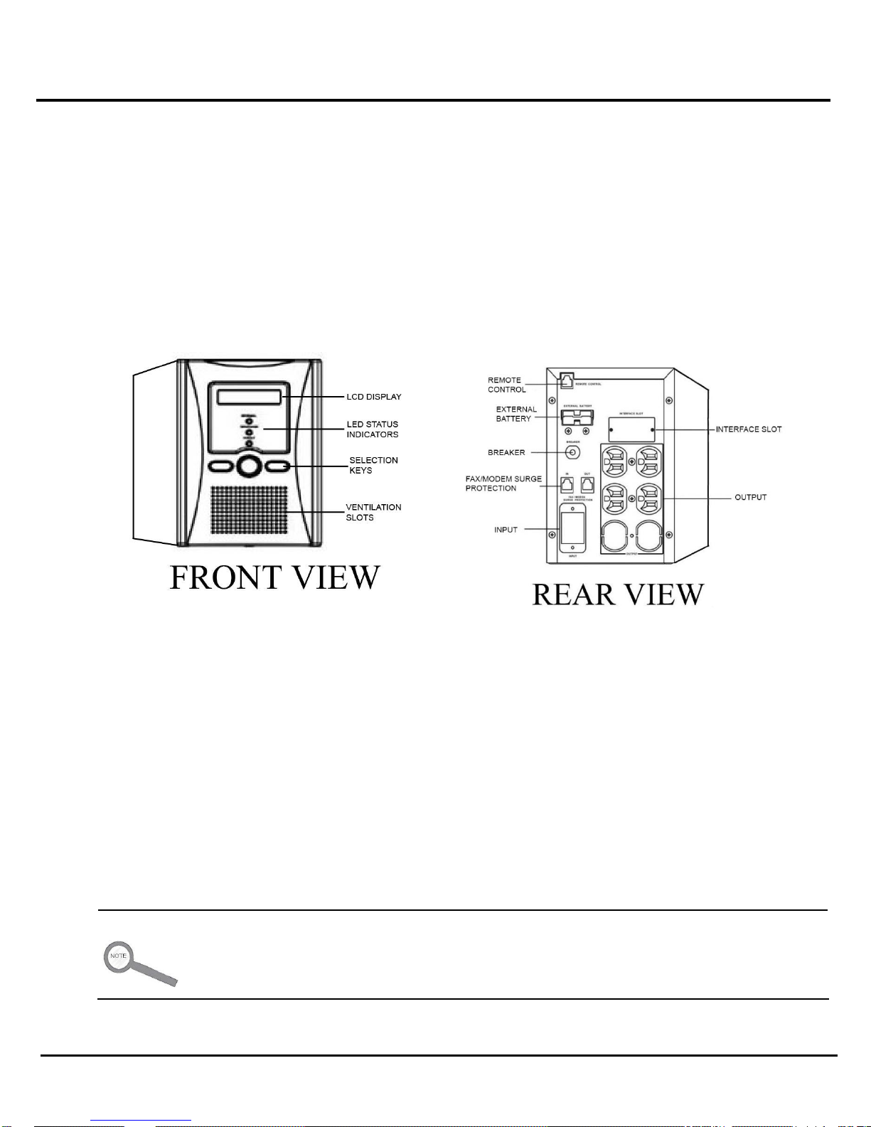
3.3—Connecting Units
For product keys showing the socket locations and other interface connection options located on the casing, see 1.1—
Key Features.
1 Connect the UPS input to an AC utility source such as a standard wall outlet. Be sure that the outlet has
the appropriate power capacity.
Caution
When connecting to the input, please note the listed current of the utility source.
Ensure that the incoming feeder is isolated and secured to prevent it from being switched
back ON again.
Connect the UPS only to a grounded wall outlet.
2 Connect the unit to the device it will be powering by plugging one (1) end of the device’s power cord into
the INTegral output socket.
Note
The output slot connects only to socket-type cords.
3 Connect the other end of the device’s power cord into the device to be powered.
Caution
Do not connect domestic appliances (hair dryers, etc.) or office equipment (laser
printers, etc.) to UPS output sockets. Connecting them will overload the system.
Connect the monitoring UPQsoft cord to the USB port or install the UPQNet-Agent9 Mini.
4
After the hardware has been connected to the port, the monitoring software is ready to be connected to a
computer and configured.
8 Power Innovations INTegral Line-Interactive Uninterruptible Power Supply—2kVA-T

Additional Manual
Connect the unit to the computer to monitor it. If UPQsoft or UPQNet-Agent9 has been
ordered, another manual will be included.
ELECTRICAL WARNING
Always be careful while handling the UPS. Batteries in the unit may emit electricity even when
the unit is disconnected.
3.4—Prestart Checklist
The UPS is positioned correctly.
The input cord is secured.
The devices to be powered are OFF.
The rated input voltage from the wall socket falls within the unit’s safe operating range.
Connected cables are placed carefully to prevent stepping/tripping hazards.
INTegral Line-Interactive Uninterruptible Power Supply Unit—2kVA-T Power Innovations 9

This page intentionally left blank.

4—Operating the Unit
4.1—Operating Cautions
While operating the unit, be sure that it has adequate ventilation space. Be sure the operating area is left free of clutter or
other objects that may block ventilation slots. Do not block off ventilation openings in the casing.
Avoid placing liquids or flammable gases near the unit during operation.
Keep the unit far away from sources of natural or artificial heat, and make sure that the system is not overloaded.
ELECTRICAL WARNINGS
Do not expose the UPS to flammable gases or corrosive liquids.
Ensure that no liquids of any kind enter the UPS unit.
Caution
Do not disconnect the main cable or unplug the unit from the wall outlet unless all breakers have
been turned OFF. Doing so will cause the system to switch to backup mode and drain the batteries.
Do not block ventilation openings in the casing.
Keep objects from within four (4) inches on all visible ventilation holes in the UPS. The added space
helps the unit ventilate.
Keep the UPS far away from sources of heat (for example, heaters or direct sunlight).
Keep the load within the correct operating range.
INTegral Line-Interactive Uninterruptible Power Supply Unit—2kVA-T Power Innovations 11

4.2—Keys and Indicators
1 LCD Display—When the unit plugs into AC power, the display light will be ON even if the unit is OFF.
Use the display to view UPS operation information, including UPS status, input/output voltage,
input/output frequency, battery voltage, battery capacity, load capacity, temperature, and event logs.
2 Up Key ( )—Press to scroll the display upward.
3 Down Key ( )—Press to scroll the display downward.
4 Left/Enter Key ( )—Press to enter the setting page and save the settings.
5 Fault LED—Red LED that indicates the UPS is in fault condition. Problems, such as an abnormal inverter
or over-temperature DC voltage, need to be solved. These conditions will likely require the assistance of
a Power Innovations Service Representative.
6 Warning LED—Yellow LED that indicates the status of the UPS should be watched carefully. Some
Warning circumstances include UPS overload or battery-backup mode.
12 Power Innovations INTegral Line-Interactive Uninterruptible Power Supply—2kVA-T

7 Normal LED—Green LED that indicates that the UPS is operating normally.
4.2.1—Basic Operations
Switch ON—Press and simultaneously for three (3)
seconds until the UPS beeps twice.
Switch OFF—Press and simultaneously for three (3)
seconds until the UPS beeps twice.
Mute—When the UPS is ON and in Battery Backup mode, the UPS
will beep every four (4) seconds. Press and
simultaneously for three (3) seconds to turn OFF the buzzer.
4.3—Information about Operations
Once the UPS is connected to the power source, the LCD display will illuminate immediately, displaying the main menu.
The Normal LED will be blinking to indicate that the inverter can be switched ON.
Start the unit by pressing and simultaneously for three (3) seconds until the buzzer beeps twice. The Normal
LED will illuminate that power is being provided to the load.
To turn the output OFF, press and the key simultaneously for three (3) seconds until the buzzer beeps twice.
The UPS will be on standby, with the LCD display illuminated and Normal LED light blinking until the AC source is
disconnected.
4.4—Navigating the Menus
Use or to select the menu display for the LCD. The menu selection screen will come up once the system is
connected to a power source.
Below, see diagrams of all menus. For information about selecting options with the menus, see 8.1—Keys and
Indicators.
Note
The menus below are based on the 220V system. For the 110V system, the menus are the same as
the 220V system, but the voltage numbers will be different.
INTegral Line-Interactive Uninterruptible Power Supply Unit—2kVA-T Power Innovations 13

1 Rated Specification Menu 2 Status Menu
3 Voltage Menu
4 Frequency Menu
14 Power Innovations INTegral Line-Interactive Uninterruptible Power Supply—2kVA-T

5 Battery Status Menu
6 Output Power Menu 7 Temperature Menu
8 History Record Menu
New Rec indicates issues occurring during the unit’s current uptime.
Old Rec indicates issues occurring during the previous uptime.
AC Fail indicates events during which the system has gone into backup mode.
OV Load indicates that the system has gone into overload condition.
INTegral Line-Interactive Uninterruptible Power Supply Unit—2kVA-T Power Innovations 15

Input Voltage
Indicates the present input voltage to the UPS unit when
AC power is present.
Output Voltage
Indicates the present output voltage of the UPS.
AC Frequency
Indicates the actual output frequency of the UPS.
Battery Voltage
Indicates the present DC voltage of the UPS battery.
Temperature
Indicates the actual temperature inside the UPS.
9 Output Voltage/ Frequency Set Menu
A In this screen, press to begin the steps for adjusting output voltage or frequency
settings.
B The cursor () will pop up to indicate the output voltage or frequency.
C Use or to adjust the output voltage (220V, 230V, and 240V are available for
the 220V system; 100V, 110V, 115V, and 120V are available for the 120V system) or
output frequency (50 or 60 Hz).
D Once the correct voltage or frequency is selected, press again to save the data.
4.5—RS-232 Computer Interface Port
The communication interface (DB9) port on the back of the UPS may be connected to a host computer. The port provides
RS-232 communication for monitoring software.
The UPS communicates with the computer by sending out RS-232 data streams to one (1) of the serial ports. Computer
interfaces can be used to monitor the following:
To interface with a computer, plug the computer’s DB9 cord into the socket on the back of the UPS. If the other end is
plugged into a computer, the computer will begin monitoring the status of the UPS.
4.5.1—DB9 Pin Assignment
PIN 2: RS-232 RXD
PIN 3: RS-232 TXD
PIN 5: GND
The other pins have no function.
16 Power Innovations INTegral Line-Interactive Uninterruptible Power Supply—2kVA-T

4.6—Protecting a Fax Machine or Modem
The Line-Interactive UPS can also protect a fax machine or modem from power surges, enabling devices to function more
consistently. For the UPS to protect equipment, the telephone line cord must be plugged into the Fax/Modem Surge
Protection jack located in the system’s rear casing.
Note
This feature is not available for the 1kVA or 1.5 kVA Rack Mount 1U models.
To protect a fax machine or modem from power surges that could damage the machine:
1 Ensure that both machines are turned OFF before connecting the cables.
2 Insert a telephone cable into the back of the machine to be protected.
3 Insert the other end of the telephone cable into the UPS. The end should be inserted into the rear jack
labeled “Fax/Modem Surge Protection.”
4 Verify that each machine is plugged into AC power before switching both machines ON.
4.7—Remote Control Display
All models but the 650 VA Tower Model and the 1kVA and 1.5kVA 1U Rack Mount model include an option to control and
read the unit remotely by using a remote control connection. This feature allows the dot-matrix LCD panel to be removed
from the front of the unit and connected remotely by using a standard straight-through Ethernet cable (CAT 5or 6).
The unit will register changes made from up to distances of 100 feet.
It will be possible to view the input and output voltage or adjust the settings while away from the unit. Any changes made
to the setting on the panel will update the unit from within the remote control’s operating range.
To use this feature, insert the remote control communication cable into the outlet labeled “Remote Control” on the back of
the rack or tower casing and then on the back of the display panel. The panel has a RJ45 communication port that will
communicate with the display as long as the back of the remote control display and the back of the remote control outlet
are connected using standard network cables.
4.8—Emergency Power OFF
This function allows the unit to stop system output immediately in an emergency situation (electrical shock, fire,
earthquake, or any other similar type of emergency). The Emergency Power OFF feature functions when the Emergency
Power OFF relay connector is plugged into the outlet on the back of the unit.
INTegral Line-Interactive Uninterruptible Power Supply Unit—2kVA-T Power Innovations 17

During an emergency, press the button on the portable controller to send a signal through the system. The circuits will be
closed and power to the unit will be shut OFF.
4.9—Storing the System
Disconnect input power from the unit’s rear panel if it will not be used for extended periods of time.
If the UPS is stored for longer than three (3) months, plug it back into a power supply for at least 24 hours to fully restore
the battery charge before use.
Cautions
If the UPS will be stored for long periods of time, the battery must be charged once for every 90 days
of storage.
Keep the unit clean by dusting it with a dry cloth.
18 Power Innovations INTegral Line-Interactive Uninterruptible Power Supply—2kVA-T

Scenario
Possible Cause
Try
AC utility power is normal. UPS is
running normally, but fault LED
illuminates. Buzzer is continual.
Fan is damaged.
Replacing the fan.
Unknown
Restarting the unit.
AC utility power is normal but UPS is
overloaded. Warning LED illuminates.
Buzzer beeps every second.
System overload between
100% and 125%.
Reducing the critical
load to less than 100%.
AC utility power is normal. Warning
LED does not fade out and buzzer
beeps every half second.
System overload between
125% and 150%.
Reducing the critical
load to less than 100%.
AC utility power is normal. Warning
LED illuminates and buzzer sounds
continually.
System overload greater
than 150%.
Reducing the critical
load to less than 100%.
5—Maintenance and Troubleshooting
5.1—Maintenance
Very little user maintenance is required. The system has no user-serviceable internal parts.
If the system gets dirty, clean it by dusting it with a dry cloth or can of air duster while the system is OFF.
DO NOT wipe down the system with a wet cloth.
5.2—Troubleshooting
If the screen lights up and alerts begin to sound although power is normal, use the table directly below.
If AC utility power input is failing, use the second table.
ELECTRICAL WARNING
This unit should not be serviced except by authorized individuals. Opening the case could
cause accidental injury or death. Follow the troubleshooting guide below. If troubleshooting
does not fix the problem, call Power Innovations.
5.2.1—Utility Power Functioning
INTegral Line-Interactive Uninterruptible Power Supply Unit—2kVA-T Power Innovations 19

Scenario
Possible Cause
Try
AC utility power fails. The
battery powers the load.Buzzer
sounds every four (4) seconds.
AC utility power failure.
Reducing the critical load to
extend backup time.
AC input may not be
connected correctly.
Checking the input rate.
Checking power connection.
AC utility fails. UPS is in battery
backup mode. Buzzer beeps
every second.
Battery power is
approaching low levels.
UPS will shut down
automatically. Save data or
disconnect loads soon.
AC utility power fails. UPS has
shut down automatically.
Battery has run out.
UPS will restart when AC utility
power is restored.
5.2.2—Utility Power Failing
20 Power Innovations INTegral Line-Interactive Uninterruptible Power Supply—2kVA-T

Capacity (VA/Watt)
2kVA/1250W
Model Type
Tower
Input
Nominal Voltage
100/110/115/120VAC
Voltage
Range
Acceptable Voltage
Range
85VAC~150VAC
Frequency
45 ~ 70 Hz Auto-sensing
Boost Transfer
85/94/97.8/102 VAC ± 2%
Boost Return
90/99/102.8/107 VAC ± 2%
Buck Transfer
115/126/132/132 VAC ± 2%
Buck Return
110/121/127/127 VAC ± 2%
Low Voltage Transfer
74/81/85/89 VAC ± 2%
Low Voltage Return
79/86/90/94 VAC ± 2%
High Voltage Transfer
130/143/150/150 VAC± 2%
High Voltage Return
125/138/145/145 VAC ± 2%
Output
Voltage
100/110/115/120 VAC re-settable via LCD panel
Voltage
Regulation
Line Mode
± 15%
Battery Mode
<3% RMS for entire battery voltage range
Frequency
Regulation
Line Mode
Synchronize to AC Mains
Battery Mode
50 Hz or 60 Hz ± 0.1 Hz
Power Factor
0.625
Wave Form
Pure sine wave
Efficiency
Line Mode
> 98%
Battery Mode
> 80%
Overload
Protection
Line Mode
> 110%, then buzzer alarm and amber LED blink continuously
Battery Mode
110%~150% for 30 seconds, >150% for 200ms, then UPS shuts down
Short
Circuit
Protection
Line Mode
Circuit breaker
Battery Mode
Electronic circuit
DC Start
Cold Start
Yes
Transfer Time
Typical
< 4 ms
Battery
Battery Voltage
36VDC
Battery Type
9AH (8.5AH)
Battery Quantity
3pcs
Backup Time
At Half Load
> 8 min
At Full Load
> 3 min
Recharging Current
0.1C~0.3C
Control Panel
LCD Display
UPS status, I/P&O/P Voltage Frequency, Load Level, Battery Voltage & Level, Temperature, Model
LED Display
Normal (Green)
Warning (Amber)
Fault (Red)
Audible Alarm
Battery Mode
Beeping every 4 seconds
Low Battery
Beeping every second
UPS Fault
Beeping continuously
Overload
Beeping twice per second
Communication
Interfaces
Standard
RS-232
Multi-Interfaces Card (Option)
Various combination of RS-232, SNMP, USB, Dry Contact, AS400, MODBUS, Enable at the same time
Environment
Operation Temperature
0–40°C; 32–104°F
Relative Humidity
0–95% non-condensing
Audible Noise
Less than 55dBA (at 1m)
Physical
(WxHxD) mm
145*215*431
Net Weight (kgs)
22.5
NEMA Outlets (100/110/115/120 VAC)
6
Safety
Conformance
Safety Standard
EN62040-1-1
EMC
EN62040-2
Marks
CE
6—Specifications
INTegral Line-Interactive Uninterruptible Power Supply Unit—2kVA-T Power Innovations 21

This page intentionally left blank.

7—Battery Information
7.1—No Battery Maintenance
No maintenance is necessary to operate the batteries. To get batteries serviced, call Power Innovations:
Power Innovations International, Inc.
Phone: 801-785-4123
Email: support@power-innovations.com
ELECTRICAL WARNINGS
This system contains batteries with a high short-circuit current. Even when disconnected from
outlet power, UPS components are still connected to batteries. Incorrect battery handling may
cause accident electric shock, injury, or death.
Do not open or destroy batteries. When open to air, batteries may emit chemicals that could
harm skin or eyes.
7.2—Storage Concerns
If the UPS will be stored for long periods of time, the battery must be charged once for every 90 days of storage.
INTegral Line-Interactive Uninterruptible Power Supply Unit—2kVA-T Power Innovations 23

This page intentionally left blank.

8—Warranty and Legal Information
8.1—Limited Warranty
Power Innovations International, Inc. (hereafter “Power Innovations”) warrants this product to be free from defects in
material and workmanship for a period of one year from the purchase date. The purchase date will be determined only
from the receipt or other proof of purchase provided by Power Innovations or other authorized resellers.
8.1.1—Rights Under This Warranty
This warranty gives you specific legal rights, and you may also have other rights which vary from state to state.
8.1.2—Part and Product Coverage
The warranty includes twelve-month coverage on parts only.
If any part or portion of the Power Innovations product fails to conform to the warranty within the warranty period,
Power Innovations, at its option, will furnish new or rectory remanufactured products for repair or replacement of that
portion or part. Replacement parts or unit may be new or refurbished and will meet specifications or the original parts
or unit.
8.1.3—Restrictions
8.1.3.1—PREVIOUS SERVICE
The product must not have been previously altered, repaired, or serviced by anyone other than a service facility
authorized by Power Innovations to renders such service, and the serial number of the product must not have
been altered or removed.
8.1.3.2—MISUSE OR ABUSE
In order to be covered by this warranty, the product will not have been subjected to accident, misuse, or abuse, or
operated contrary to the instructions contained in this manual. Any such conditions will void this warranty and the
purchaser assumes all the expenses associated with servicing or replacement, including travel expenses, parts,
and labor.
8.1.3.3—NON-TRANSFERABLE
This warranty is limited to the original purchaser of the product and is not transferable.
This warranty covers only Power Innovation-supplied components. Service required as a result of third-party
components is not covered under this warranty.
INTegral Line-Interactive Uninterruptible Power Supply Unit—2kVA-T Power Innovations 25

8.2—Warranty Claims
8.2.1—Proof of Purchase
Proof of purchase will be required by Power Innovations to substantiate date of purchase. Such proof of purchase
must be an original bill of sale or receipt containing name and address of seller, purchaser, and the serial number of
the product.
8.2.2—Notifying Power Innovations
Within a reasonable time, but in no case to exceed thirty (30) days after discovery of a defect, the purchaser shall
contact Power Innovations at 801-785-4123. Subject to the limitations specified herein, a Power Innovations service
representative will determine the appropriate course of action to repair the non-conforming product warranted
hereunder.
8.2.3—Product Shipping
If it is determined that the product or part must be shipped back to the manufacturer for repair, the purchaser will
assume liability and pay for shipping to Power Innovations or an authorized service center. Power Innovations or an
authorized service center will pay for shipping to return the repaired product to the customer.
8.24—Prior Approval
All products returned for service MUST have prior approval and an RMA number. If it is deemed necessary to return
this equipment to the factory for servicing, contact the Power Innovations Service Department for authorization and
an RMA number.
8.3—Limitation of Remedies
Power Innovations’ entire liability and the User’s exclusive remedy will be repair or replacement of the unit if all conditions
described under 8.1—Limited Warranty have been met.
8.3.1—Indirect Damages
In no event will Power Innovations be liable for indirect, special, incidental, consequential, or exemplary damages of
any kind whatsoever arising out of the use of this unit, including (without limitation) lost profits, business interruption,
or loss of data, whether any claim is based upon theories of contract, negligence, strict liability, tort, or otherwise.
8.4—Customer Service
Questions concerning the operation, repair, or maintenance of this equipment should be directed to the Power Innovations
Service Department. When making such an inquiry, provide the Service Department with the model number, serial
number, and approximate date that the equipment was received.
It is often unnecessary to return a failed piece of equipment since this equipment uses plug-in type assemblies
throughout. Replacement assemblies for systems covered by this manual are usually in stock at the factory and available
for immediate shipment.
26 Power Innovations INTegral Line-Interactive Uninterruptible Power Supply—2kVA-T

Company Information
The INTegral Line-Interactive UPS System is distributed by Power Innovations International, Inc. If there are any
questions or comments about this product, please call us:
Power Innovations International, Inc.
Phone: 801-785-4123 Fax: 801-785-6999
Email: support@power-innovations.com
Web: www.power-innovations.com
Product names mentioned herein may be trademarks and/or registered trademarks of their respective companies.
Version 1.0
Copyright © March 2015
All rights reserved.
INTegral Line-Interactive Uninterruptible Power Supply Unit—2kVA-T Power Innovations 27
 Loading...