

Page 1

Operation Manual
POWERHORSE ENGINES
SAVE THIS MANUAL FOR FUTURE USE.
PGM45006 04/15/15 revA
Page 2

California Proposition 65
WARNING:
The engine exhaust from this product and this product
contains chemicals known to the state of California to
cause cancer and birth defects, or other reproductive harm.
Page 3
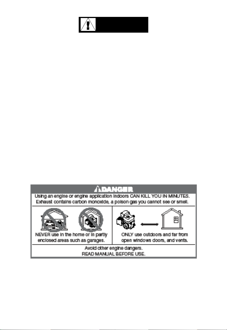
DANGER
CARBON MONOXIDE HAZARD
NEVER use engine inside homes, garages, crawl spaces,
or other partially enclosed areas. Poisonous gases that can
be harmful or fatal can build up in these areas. Using a fan
and opening doors or windows does NOT provide enough
fresh air.
Engine exhaust contains carbon monoxide - a poisonous
gas that can be harmful or fatal. You CANNOT see or smell
this gas.
Use a battery-powered carbon monoxide detector when
running an engine.
If you start to feel sick, dizzy, or weak while using an engine,
shut it off and get to fresh air RIGHT AWAY. See a doctor.
You may have carbon monoxide poisoning.
Page 4

Introduction
When using this engine, your safety and the safety of others should
be your top priority.
To assist you in making informed decisions regarding safety, we have provided
operating procedures and other information on labels and in this manual. This
information warns you of potential hazards that could hurt you or others.
Please stay safety conscious when using this engine.
We have provided important safety information in a variety of forms, including:
• Safety Labels: placed on the engine.
• Safety messages: preceded by a safety alert symbol and one of three signal words,
DANGER, WARNING, or CAUTION. These safety alert symbols mean:
DANGER
WARNING
CAUTION
• Safety Headings: such as IMPORTANT SAFETY INSTRUCTIONS.
• Safety Section: such as ENGINE SAFETY.
• Instructions: How to use this engine correctly and safely.
Thoroughly read and review this manual to know how to stay safe and get maximum
benet and enjoyment from using this engine.
If you do not follow instructions, it WILL cause you
SERIOUS INJURY or DEATH.
If you do not follow instructions, it MAY cause you
SERIOUS INJURY or DEATH.
If you do not follow instructions, it may cause you
SERIOUS INJURY or EQUIPMENT DAMAGE.
Powerhorse Engines Manual 1rev. 04/15/15
Page 5

Engine Safety
IMPORTANT SAFETY INSTRUCTIONS
Accidents occur less frequently when instructions are followed, the operator is safety
conscious and the engine is properly maintained. Some of the most common hazards
are discussed below, along with the best way to protect yourself and others.
Owner and Operator Responsibilities
Owners and operators should perform the following suggestions:
• Carefully read the owners manual.
• Follow the instructions in this manual carefully.
• Familiarize yourself with all controls and know how to stop the engine quickly
in case of an emergency.
• Keep children away from the engine and do not let them operate it. Keep children
and pets away from the area of operation.
• Operate this engine in well-ventilated areas. NEVER run engine indoors.
Refueling the Engine
Gasoline is extremely ammable, and gasoline vapor can explode. When refueling
the engine, take the following precautions.
• Perform when the engine is cool.
• Refuel outdoors in well-ventilated areas.
• The engine should not be running.
• Make sure the engine is grounded to prevent static electrical spark.
• Do not smoke or use cell phones when refueling.
• Keep away from ames or sparks.
• If spillage occurs, be sure all areas are dry and vapor has dissipated prior to starting
the engine.
Powerhorse Engines Manual 2rev. 04/15/15
Page 6
Engine Safety CONTINUED
Exhaust / Muffler
Engine exhaust is dangerous because of intense heat and emission of carbon
monoxide (poisonous gas).
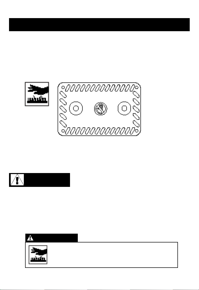
• The mufer becomes very hot during operation and remains hot for a while after
stopping the engine. Do not touch the mufer while it is hot. Do not store the engine
until it is cool.
• To prevent re hazards and for adequate ventilation, keep the engine at least 3 feet
(1 meter) away from building walls and other equipment during operation. Do not
place ammable objects close to the engine.
• Carbon Monoxide Hazard:
Exhaust gas contains carbon monoxide, a poisonous
DANGER
gas. Avoid inhalation of exhaust gas. Always run the
engine in a well-ventilated area. Never run the
engine indoors.
Other Equipment
Review the instructions provided with the equipment powered by this engine for any
additional safety precautions that should be observed in conjunction with engine
startup, shutdown, operation, or protective safety gear that may be needed to operate
the equipment.
WARNING
Do not touch hot sections of engine (see muffler figure
above). The hot sections of the engine can cause severe
burns.
Powerhorse Engines Manual 3rev. 04/15/15
Page 7

Contents
Introduction 1
Engine Safety 2–3
Controls & Features 5
Before Operation 6–7
Pre-Operation Checks 6–7
Operation 7–10
Safe Operation Precautions 7
Starting the Engine Manual 8
4 Step Starting Procedure 8
Starting the Engine Electric 8
Stopping the Engine Manual 9
Stopping the Engine Electric 9
Setting Engine Speed 9
High Altitude Operation 10
Servicing Your Engine 11–16
The Importance of Maintenance 11
Maintenance Safety 12
Refueling 13
Fuel Recommendations 14
Engine Oil Level Check 14
Engine Oil Change 15-16
Engine Oil Recommendations 15
Air Filter Inspection 16
Air Filter Service 16
Spark Plug Service 16
Helpful Tips and Suggestions 17–19
Storing your engine 17
Maintenance Schedule 18
Storage Precautions 19
Transportation 19
Technical & Consumer Information 20-21
Emission Control System Information 20
Consumer Information 20
Engine Model Number & Serial Numbering System 21
Warranty 22-24
Specications 25
Powerhorse Engines Manual 4rev. 04/15/15
Page 8
Controls & Features
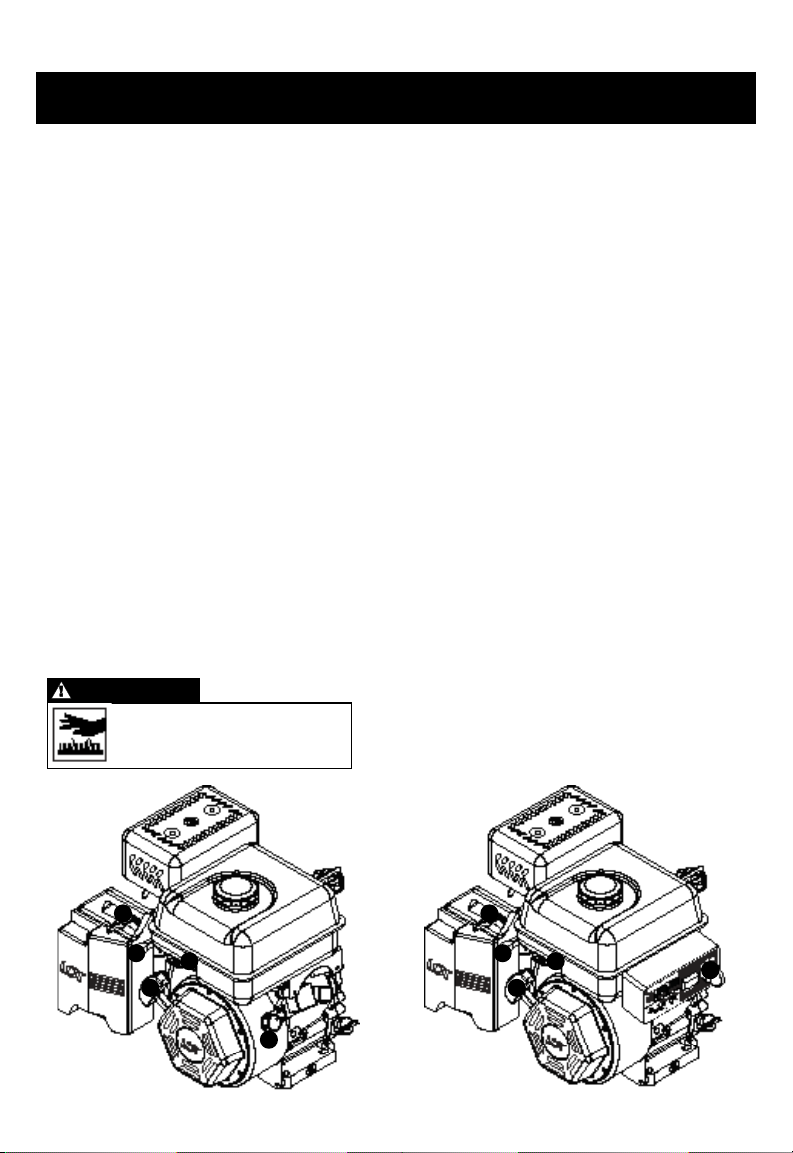
CONTROLS
1. Fuel Valve
The fuel valve opens and closes the passage between the fuel tank and the carburetor. The fuel
valve must be in the ON position for the engine to run. When the engine is not in use, be sure the
fuel valve is in the OFF position to prevent carburetor ooding and
to reduce the possibility of fuel leakage.
2. Engine ON/OFF Switch (per engine specification) (fig. 1)
The engine switch enables and disables the ignition system. Turn the engine switch to
the ON position to start the engine. Turn the engine switch to the OFF position to stop the engine.
2A. Engine Off/On/Start Switch (electric start) (fig. 2)
The engine off/on/start switch enables the ignition system and engages the electric starter. Insert
key and turn switch to the START position to engage the electric starter (do not hold longer
the 3-seconds), then release the key back to the RUN position when engine starts. Repeat if
necessary. Turn the switch to the OFF position to stop the engine.
3. Choke Lever
The choke lever opens and closes the choke valve in the carburetor. The “ON” position enriches
the fuel mixture which makes it easier when starting a cold engine. The opposite position provides
the correct fuel mixture for operation after engine warms up.
4. Throttle Lever (per engine specification)
The throttle lever controls engine speed (RPMs). Moving the throttle lever in the directions shown
makes the engine run faster or slower. (Non-generator applications.)
5. Recoil Starter Grip
Pulling the starter grip operates the recoil starter to crank the engine. Always grip snugly and have
your body positioned properly when pulling. Keep thumb on the end of the handle in case of kick-back.
WARNING
Do not touch hot sections of engine.
The hot sections of the engine can
cause severe burns.
3
4
1
5
2
3
4
1
5
2A
fig. 1 fig. 2
Powerhorse Engines Manual 5rev. 04/15/15
Page 9
Before Operation
PRE-OPERATION CHECKS
For your safety, and to maximize the service life of your equipment, it is very important
to take a few moments before you operate the engine to check its condition. Be sure to
take care of any problem you nd, or have your servicing dealer correct it, before you
operate the engine.
WARNING
Improperly maintaining this engine or failing to correct a problem
before operation, could cause a malfunction in which you could
be seriously injured.
Always perform a pre-operation inspection before each operation
and correct any problem.
Before beginning your pre-operation checks, be sure the engine is level and the engine
switch is in the OFF position (per engine specication).
Check the General Condition of the Engine
• Remove any excess dirt or debris, especially around the mufer, recoil starter, and
cylinder head ns.
• Inspect for signs of damage and oil leakage.
• Be sure all shields and covers are in place. All nuts, bolts, and screws must be tight.
Check the Engine
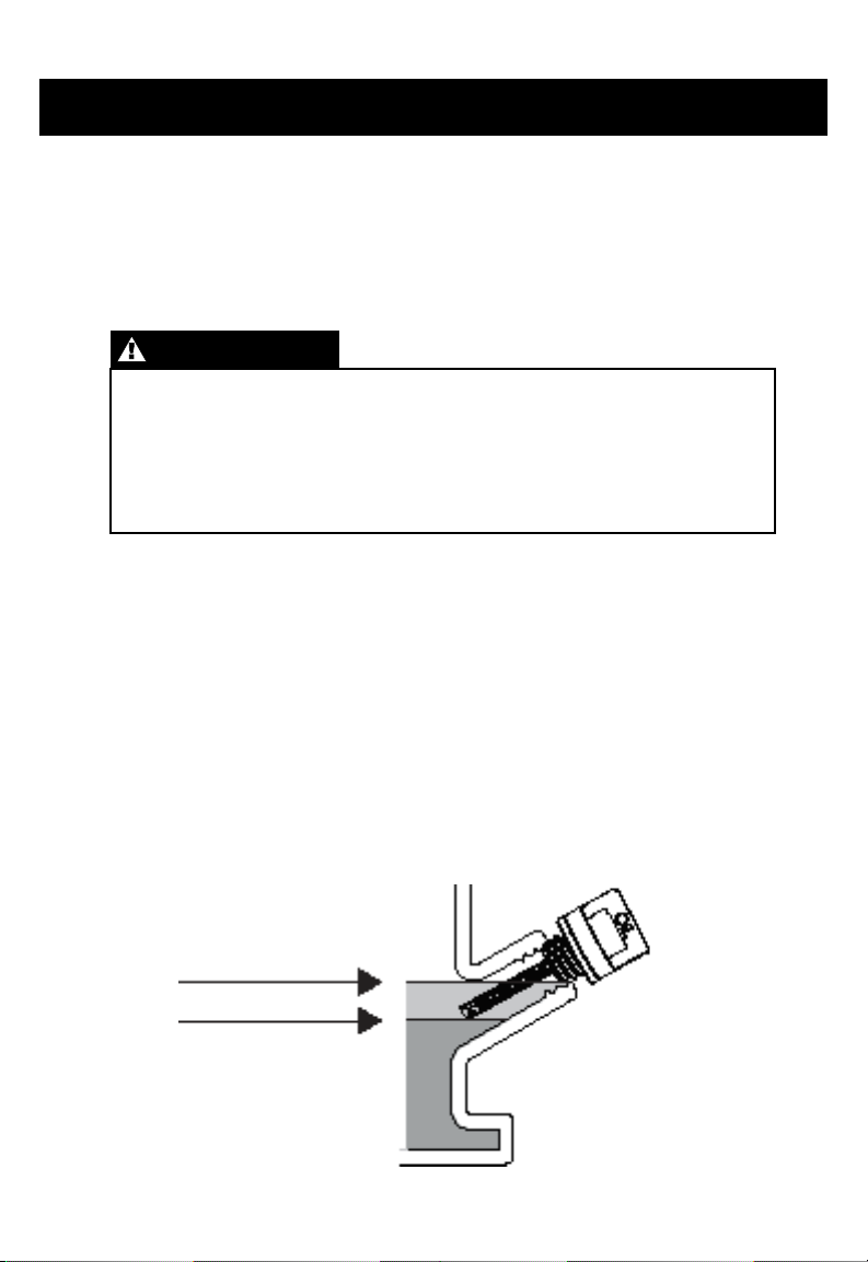
• Check the engine oil level. Running the engine with a low oil level or improper oil
can cause engine damage. To avoid the inconvenience of an unexpected shutdown,
always check the engine oil on a level surface before startup.
Max Upper Level
Min Lower Level
Powerhorse Engines Manual 6rev. 04/15/15
Page 10

Before Operation CONTINUED
• Check the air lter. A dirty air lter will restrict air ow to the carburetor, reducing
engine performance and can cause excessive wear on the engine.
• Check the fuel level before start-up. Since the engine must be cool before
refueling, starting with a full tank will help to eliminate or reduce operating
interruptions for refueling.
Check all Equipment Powered by this Engine
Review the instructions provided with the equipment powered by this engine for
all precautions and procedures that should be followed before starting the engine.
Operation
SAFE OPERATING PRECAUTIONS
Please review this section BEFORE OPERATION.
WARNING
Carbon monoxide gas is toxic.
Breathing it can cause unconsciousness and/or death.
Avoid any areas or actions that expose you to carbon monoxide.
WARNING
DO NOT place the hands on or near the exhaust system while starting.
Review the instructions provided with the equipment powered by this
engine for any safety precautions that should be observed in conjunction
with starting, shutting down, or operating the engine.
Powerhorse Engines Manual 7rev. 04/15/15
Page 11
Operation CONTINUED
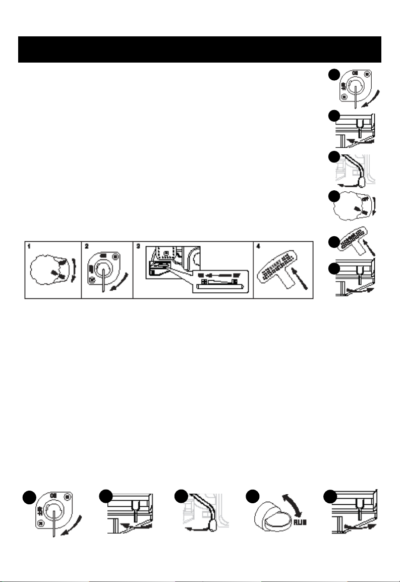
STARTING THE ENGINE (Manual Start)
1. Place the fuel valve to the ON position (if applicable).
2. To start a cold engine, move the choke lever to the ON position.
3. Move the throttle lever away from the SLOW position, about 1/3 of the
way toward the FAST position (per engine specication).
4. Turn the engine switch to the ON position (per engine specication).
5. Pull the recoil handle.
6. If the choke lever has been moved to the ON position to start the
engine, gradually move it to the opposite position as the engine
warms up.
4 STEP STARTING PROCEDURE*
*Per engine specication
STARTING THE ENGINE (Electric Start)
1. Place the fuel valve to the ON position (if applicable).
2. To start a cold engine, move the choke lever to the ON position.
1
2
3
4
5
6
3. Move the throttle lever away from the SLOW position, about 1/3 of the way toward the
FAST position (per engine specication).
4. Insert key and turn switch to the START position to engage the electric starter (do
not hold longer the 3-seconds), then release the key back to the RUN position when
engine starts or 3-seconds maximum. Repeat if necessary.
5. If the choke lever has been moved to the ON position to start the engine, gradually
move it to the opposite position as the engine
warms up
1
2 3
4
5
Powerhorse Engines Manual 8rev. 04/15/15
Page 12
Operation CONTINUED
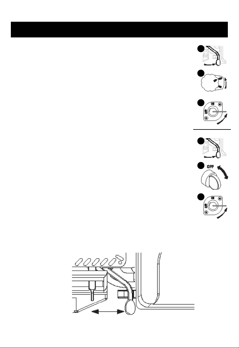
STOPPING THE ENGINE (Manual Start)
To stop the engine in an emergency, turn the engine switch to the OFF
position. Under normal conditions, use the following procedure (per engine
specication).
1. Move the throttle lever to the SLOW position and allow the engine to
run slowly for cool down. This reduces the chance of backre.
(Non-generator applications.)
2. Turn the engine switch to the OFF position (per engine specication).
3. Turn the fuel valve lever to the OFF position.
STOPPING THE ENGINE (Electric Start)
To stop the engine in an emergency, turn the engine switch to the OFF
position. Under normal conditions, use the following procedure (per engine
specication).
1. Move the throttle lever to the SLOW position and allow the engine to
run slowly for cool down. This reduces the chance of backre. (Nongenerator applications.)
2. Turn the engine switch to the OFF position (per engine specication).
3. Turn the fuel valve lever to the OFF position.
1
2
3
1
2
3
SETTING ENGINE SPEED
Position the throttle lever for the desired engine speed. For engine speed recommendations,
refer to the instruction manual provided with the equipment powered by this engine. (Nongenerator applications.)
Increases RPM Decreases RPM
Powerhorse Engines Manual 9rev. 04/15/15
Page 13

Operation CONTINUED
HIGH ALTITUDE OPERATION
Carburetor Modifications
The standard carburetor air-fuel mixture may be too rich when operated at high altitude
resulting in possible decreased performance and increased fuel consumption. Please
have an authorized POWERHORSE Service Center modify this engine’s carburetor if it
is operated continuously above 5000 feet. Failure to modify may result in poor engine
performance, spark plug fouling, hard starting, and increased emissions.
Carburetor modication by an authorized POWERHORSE Service Center will improve
performance and allow this engine to continually meet US EPA and California ARB
emission standards throughout its useful life.
Important Note
When the carburetor has been modied for high altitude operation, the air-fuel mixture
may be too lean for operation at 5000 feet or below. This could result in the engine
overheating and could cause serious engine damage. Please have an authorized
POWERHORSE Service Center restore high altitude converted carburetors back to the
original factory specication before operating below 5000 feet.
To locate the nearest POWERHORSE dealer, please visit our website or call:
952-894-9510
Powerhorse Engines Manual 10rev. 04/15/15
Page 14

Servicing Your Engine
THE IMPORTANCE OF MAINTENANCE
Protect yourself and your equipment by properly maintaining your engine. Proper engine
maintenance is necessary for safe, economical, and trouble-free operation.
WARNING
Improperly maintaining this engine, or failure to correct a problem
before operation, can cause a malfunction in which you can be
seriously hurt or killed.
Always follow the inspection and maintenance recommendations
and schedules in this owner’s manual.
To assist you in properly caring for your engine, the following pages include routine
inspection procedures and simple maintenance procedures using basic hand tools.
Service tasks that are more difcult or which require special tools should be handled by
professionals and are normally performed by a service technician or qualied mechanic.
If you operate your engine under stressful conditions such as sustained high-load or
high-temperature operation, or use your engine in unusually wet or dusty conditions,
servicing should be more frequent. Consult your service technician for recommendations
applicable to your individual needs and use.
See Maintenance Schedule for normal and extreme operation
condition differences.
NOTE
Powerhorse Engines Manual 11rev. 04/15/15
Page 15
Servicing Your Engine CONTINUED
MAINTENANCE SAFETY INSTRUCTIONS
This manual contains very important safety precautions. However, we cannot warn you
of every conceivable hazard that can arise while performing maintenance. You must
decide whether or not you should perform a given task and always be safety conscious.
WARNING
Failure to properly follow maintenance instructions and
precautions can cause you to be seriously hurt or killed.
Always follow the procedures and precautions in the
owner’s manual.
Safety Precautions
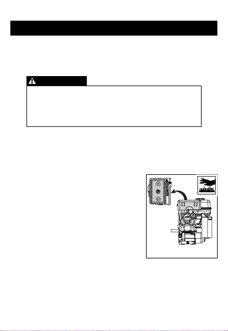
• Make sure the engine is not running, is turned OFF, spark plug cap is removed from
spark plug, and engine is cooled off before you begin any maintenance or repairs.
This can prevent several potential hazards, such as the following:
Carbon monoxide poisoning
from engine exhaust.
Run engine in a well-ventilated area.
Burns from hot parts.
Let the engine and exhaust system cool-off before
touching. (see drawing right)
Injury from moving parts.
Do not run the engine unless instructed to do so.
• Before you begin maintenance, read all instructions
and make sure you have the tools and skills required.
• To reduce the possibility of re or explosion, be alert when working around gasoline.
Use only a nonammable solvent, not gasoline, to clean parts. Keep cigarettes,
sparks and ames away from all fuel-related parts.
• It is suggested to keep a re extinguisher close by when performing maintenance.
Your servicing dealer knows your engine best and is equipped to maintain and repair it.
Engine Hot Spots
Powerhorse Engines Manual 12rev. 04/15/15
Page 16
Servicing Your Engine CONTINUED
REFUELING
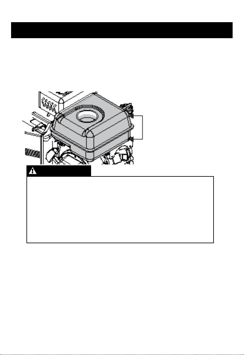
With the engine stopped and cool, remove the fuel tank cap and check the fuel level.
Rell the tank if the fuel level is low. Leave enough area in the tank to allow for fuel
expansion caused by heat. This will help prevent fuel from being forced from the tank
onto a hot surface. NEVER FILL TANK ABOVE MARKED RECOMMENDATIONS ON
FILLER NECK.
Maximum
Minimum
WARNING
Gasoline is highly flammable and explosive.
You can be burned or seriously injured when handling fuel.
• Stop the engine and keep heat sparks and flame away.
• Only handle fuel outdoors.
• Wipe up spills immediately.
Refuel in a well-ventilated area with the engine OFF and cool. Avoid spilling fuel.
Do NOT ll above the fuel strainer marking. After refueling, tighten the fuel tank cap
securely. Refuel the engine in a properly ventilated location and away from where
fuel fumes may reach ames or sparks. Keep fuel away from appliance pilot lights,
barbecues, electric appliances, power tools, and other electric appliances.
Spilled fuel is a re hazard and it causes environmental damage. Wipe up spills
immediately. Do not use cell phones or other electronic devices while refueling. Prevent
static electricity when refueling. Fuel can damage paint and plastic. Do not spill fuel
when lling your fuel tank. Damage caused by spilled fuel is not covered under warranty.
Powerhorse Engines Manual 13rev. 04/15/15
Page 17
Servicing Your Engine CONTINUED
FUEL RECOMMENDATIONS
Use unleaded gasoline with a pump octane rating of 86 or higher. These engines
operate best on unleaded gasoline.
Do NOT use stale or contaminated gasoline or an oil/gasoline mixture. Avoid getting dirt
or water in the fuel tank. Use only proper fuel containers that are properly marked.
Maximum recommended ethanol content: 10%
ENGINE OIL LEVEL CHECK
Check the engine oil level with the engine stopped and with the engine
in a level position.
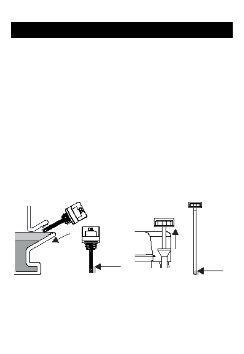
1. Remove either side mounted ller cap dipstick or high oil ll dipstick and wipe it clean.
2. Insert the dipstick into the ller neck and turn clockwise until fully seated. Then
remove the dipstick by turning it counter-clockwise. Check the oil level shown on
the dipstick.
3. If the oil level is low, ll to the edge of the oil ller hole with the recommended oil.
4. Securely screw in the ller cap/dipstick. Running the engine with a low oil level can
cause engine damage. Always check the engine oil before start up.
Fill if oil is
below letter
“L” on the
filler cap
Fill if oil
is below
“Add”
on the
dipstick
ENGINE OIL CHANGE
Drain the used oil while the engine is warm. Warm oil drains quickly and completely.
Avoid contact with hot oil.
1. Place a suitable container below the engine to catch the used oil then remove
the ller cap/dipstick and the drain plug.
continued on next page
Powerhorse Engines Manual 14rev. 04/15/15
Page 18
Servicing Your Engine CONTINUED
2. Allow the used oil to drain completely, then reinstall the drain plug, and tighten
it securely. Do not over tighten. Dispose of used motor oil in a manner that is
compatible with the environment. We suggest you take used oil in a sealed container
to your local recycling center or service station for reclamation.
Do not throw used oil in the trash, pour it on the ground, or pour down a drain.
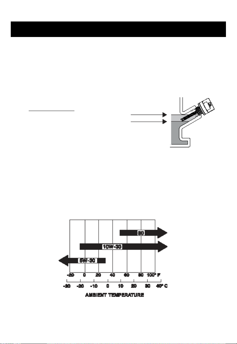
3. With the engine in a level position, ll to the outer edge of the oil ller hole with the
recommended oil.
Engine Oil Capacities
136cc - 16 oz (.473 liter)
208cc - 16 oz (.473 liter)
291cc - 32 oz (.946 liter)
414cc - 38 oz (1.123 liter)
Max Upper Level
Min Lower Level
• NOTICE
Running the engine with a low oil level can cause engine damage.
4. Securely screw in the ller cap/dipstick.
ENGINE OIL RECOMMENDATIONS
Engine oil affects performance and service life. Use 4-stroke automotive detergent oil.
SAE 10W-30 is recommended for general use. Other viscosities shown in the chart may
be used when the average temperature in your area warrants.
The SAE oil viscosity and service classication are in the API label on the oil container.
Use API SERVICE category SJ engine oil, or better.
Powerhorse Engines Manual 15rev. 04/15/15
Page 19

Servicing Your Engine CONTINUED
AIR FILTER INSPECTION
Remove the air cleaner cover and inspect the lter. Use caution to avoid dropping debris
into the air passage. Always replace damaged lter elements.
AIR FILTER SERVICE
A dirty air lter will restrict air ow to the carburetor, which will reduce engine
performance. When an air lter becomes dirty, replace it immediately.
Operating the engine without an air lter or with a damaged air lter will allow dirt to enter
the engine, causing the engine to wear rapidly. This type of damage is not covered by the
Limited Warranty.
SPARK PLUG SERVICE
F6RTC (Torch) Plug Recommended
Cross References:
• Champing plug cross reference is: RN9YC (some tables show RN9YCC)
• NGK plug cross reference: BPR6ES
• BOSCH plug cross reference is: WR6DC
• NOTICE
Using an incorrect spark plug may cause engine damage.
1. When engine is cool, disconnect the spark plug cap and remove any debris from the
spark plug area with high pressure air.
2. Remove the spark plug with a 13/16-inch spark plug wrench.
3. Inspect the spark plug. Replace it if the electrodes are worn or if the insulator is
cracked or chipped. Spark plug gap should be set to 0.027 - 0.030 inches.
4. Install the spark plug carefully to avoid cross threading. Screw in spark plug by hand
until it stops turning.
5. Tighten the spark plug with a 13/16-inch spark plug wrench. Tighten 1/4 turn after the
spark plug seats.
• NOTICE
A loose spark plug can overheat and damage the engine. Over-tightening the spark
plug can damage the threads in the cylinder head.
6. Attach the spark plug cap. Ensure spark plug cap snaps into place securely.
Powerhorse Engines Manual 16rev. 04/15/15
Page 20

Helpful Tips & Suggestions
STORING YOUR ENGINE
Storage Preparation
Proper storage preparation keeps your engine trouble-free and clean. The following
steps will assist in keeping rust and corrosion from impairing your engine’s function and
appearance, and will make the engine easier to start when using again.
Cleaning
If the engine has been running, allow it to cool for at least half an hour before cleaning.
Clean all exterior surfaces and apply a light lm of oil or WD-40 to prevent rust.
• Do not spray water into mufer or air cleaner. Water in the air cleaner will soak the air
lter, and water that passes through the air lter or mufer can enter the cylinder and
cause severe damage.
• Water contacting a hot engine can cause damage. If the engine has been running,
allow it to cool for at least half an hour before washing.
Adding a Fuel Stabilizer to Extend Fuel Storage Life
1. Turn the fuel valve off while engine is running and allow the engine to run
until it stops. Turn engine OFF when it begins surging to avoid engine damage.
2. Add fuel stabilizer, following the manufacturer’s instructions.
3. Turn fuel valve on after adding fuel stabilizer
4. Re-start engine.
5. Run the engine outdoors for 1 minute to be sure that treated gasoline has replaced
the untreated gasoline in the carburetor.
6. Slow the engine to an idle speed. (Non-generator application.)
7. Repeat step 1 above.
Powerhorse Engines Manual 17rev. 04/15/15
Page 21
Helpful Tips & Suggestions CONTINUED
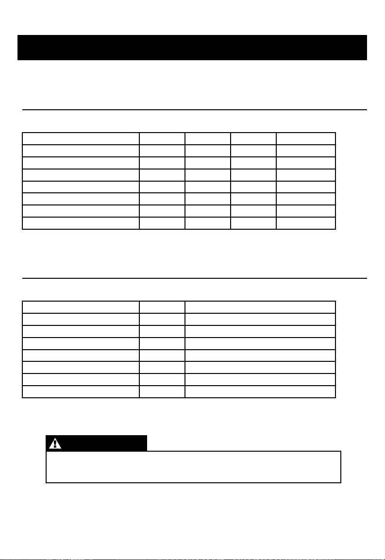
MAINTENANCE SCHEDULE
Normal Operating Conditions (less than 40 hrs. per year)
EACH
USE
Engine Oil Level
Engine Oil
Air Filter
Spark Plug*
Cylinder/Head Fins
Oil Leaks
Bolts
Fuel Hose Clamps
* Spark plug gap to be set to 0.027 - 0.030 inches.
Check
Check
Check
Check
Check
FIRST
MONTH
Replace Replace
Extreme Operating Conditions (greater than 40 hrs. per year)
EACH
USE
Engine Oil Level
Engine Oil
Air Filter
Spark Plug*
Cylinder/Head Fins
Oil Leaks
Bolts
Fuel Hose Clamps
* Spark plug gap to be set to 0.027 - 0.030 inches.
Check
Check
Check
Check
Check
Check
EVERY 40 HOURS
Drain and Replace
EVERY
6 MONTHS
Replace
Replace
Clean
ONCE
A YEAR
Clean / Replace
ReplaceClean
Clean
NOTE
Following proper maintenance is critical under extreme
operating conditions.
Powerhorse Engines Manual 18rev. 04/15/15
Page 22

Helpful Tips & Suggestions CONTINUED
STORAGE PRECAUTIONS
If your engine will be stored with gasoline in the fuel tank and in the carburetor, there is
the possible hazard of gasoline vapor ignition. Choose a well-ventilated storage area
away from heat, sparks, ames, and any appliance that operates with a ame such as
a furnace, water heater, or clothes dryer. Avoid any area with a spark-producing electric
motor, garage door openers, or where power tools are operated.
Avoid storage areas with high humidity which causes rust and corrosion. Leave the fuel
valve lever in the OFF position to reduce the possibility of fuel leakage.
Position the equipment so the engine is level to avoid fuel or oil leakage. When
the engine and exhaust system are cool, cover the engine to keep out dust. A hot
engine and exhaust system can ignite or melt certain materials. Do not use sheet
plastic as a dust cover. A nonporous cover can trap moisture around the engine causing
rust and corrosion.
Removal From Storage
Check your engine as described in the BEFORE OPERATION chapter of this manual. If
refueling is required, only use fresh gasoline.
TRANSPORTING
Transport only when engine is cool. A hot engine and exhaust system can burn you
and can ignite some materials. Keep the engine level when transporting to reduce the
possibility of fuel leakage. Position the fuel valve lever to the OFF position. Secure the
engine to prevent movement during transporting to prevent potential injury and damage
to the engine.
Powerhorse Engines Manual 19rev. 04/15/15
Page 23

Technical & Consumer Information
EMISSION CONTROL SYSTEM INFORMATION
The U.S. and California Clean Air Acts
EPA and California regulations require all manufacturers to furnish written instructions
describing the operation and maintenance of emission control systems.
The following instruction and procedures must be followed in order to keep the emissions
from your engine within the emission standards.
Tampering and Altering
Tampering with or altering the emission control system may increase emissions beyond
the legal limit. Among those acts that constitute tampering are:
• Removal or alteration of any part of the intake, fuel or exhaust systems.
• Altering or defeating the governor linkage or speed-adjusting mechanism to cause
the engine to operate outside its design parameters.
CONSUMER INFORMATION
Manufacturer Publications
These publications will give you additional information for maintaining and repairing
your engine. You may order them online at most book retailing web sites.
Small Engine Repair — Chilton Manual
This manual covers complete maintenance and overhaul procedures. It is intended
to be used by a skilled technician.
Powerhorse Engines Manual 20rev. 04/15/15
Page 24
Technical & Consumer Information
ENGINE MODEL NUMBER & SERIAL NUMBERING SYSTEM
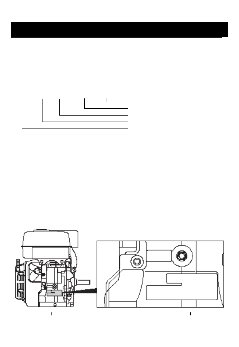
The rst two lines of an engine’s number is the model number. It is alphanumeric
and engraved on the side of the block to the right of the recoil. The third line is
alphanumeric and is also the serial number.
Engine Serial Number Sequence
09 65H 12 00001 A:
Example:
Engine Serial Number 0965H1200001A represents:
09: 2009
65H: 208cc Horizontal Engine Series (Refer to Engine Model Number System)
12: December
00001: 1st Engine Produced During Month of December
A: Horizontal Assembly Line
Note: Refer to engine model number system for correct model number breakdown.
Note: The POWERHORSE Engine Model Number and Serial Numbering System is
subject to be changed or edited at any time.
Assembly Line Designation (A, B, C, D)
Sequential Engine Number
Produced Month
Engine Series Designation (80V, 40H, 65H, 90H, 12H)
Produced Year
Engine Model Number Location
Model Number
PW1HK18650
781DE-ABGJOQUVYE1M
1065H0503152A
Serial Number
Powerhorse Engines Manual 21rev. 04/15/15
Page 25

Warranty
POWERHORSE
EMISSION CONTROL WARRANTY STATEMENT
YOUR WARRANTY RIGHTS AND OBLIGATIONS
The California Air Resources Board, United States
Environmental Protection Agency (US EPA), and
POWERHORSE are pleased to explain the emissions control
system warranty on your 2015 small off-road engine (SORE).
In California, new small off-road engines must be designed,
built and equipped to meet the State’s stringent anti-smog
standards. POWERHORSE must warrant the emission
control system (EEC) on your small off-road engine for the
periods of time listed below provided there has been no
abuse, neglect or improper maintenance of your small offroad engine.
Your emission control system may include parts such as
the carburetor or fuel tanks, fuel lines, fuel caps, valves,
canisters, filters, vapor hoses, clamps, connectors, and other
associated components.
MANUFACTURER’S WARRANTY COVERAGE
This emissions control system is warranted for two years.
If any emissions-related part on your equipment is defective,
the part will be repaired or replaced by POWERHORSE.
You are responsible for presenting your small off-road
engine to a POWERHORSE distribution center as soon as a
problem exists. The warranty repairs should be completed
in a reasonable amount of time, not to exceed 30 days. If
you have any questions regarding your warranty rights and
responsibilities, you should contact POWERHORSE at one of
the following:
Northern Tool + Equipment
2800 Southcross Drive West
Burnsville, Minnesota 55306
Phone: 952-894-9510
Fax: 952-894-1020
OWNER’S WARRANTY RESPONSIBILITIES
As the small off-road engine owner, you are responsible
for the performance of the required maintenance listed in
your owner’s manual. POWERHORSE recommends that
you retain all receipts covering maintenance on your small
off-road engine, but POWERHORSE cannot deny warranty
solely for the lack of receipts or for your failure to ensure the
performance of all scheduled maintenance.
As the small off-road engine owner, you should however
be aware that POWERHORSE may deny you warranty
coverage if your small off-road engine or a part has failed
due to abuse, neglect, improper maintenance or unapproved
modifications.
Powerhorse Engines Manual 22rev. 04/15/15
Page 26

Warranty CONTINUED
GENERAL EMISSIONS WARRANTY COVERAGE
POWERHORSE’s application for certification warrants to the
ultimate purchaser and each subsequent purchaser that the
engine is:
Designed, built, and equipped so as to conform with all
applicable regulations and,
Free from defects in materials and workmanship that cause
the failure of a warranted part to be identical in all material
respects to the part as described in the POWERHORSE’s
application for certification.
The warranty period begins on the date the engine or
equipment is delivered to an ultimate purchaser or first
placed in service. The warranty period is two years.
Subject to certain conditions and exclusions as stated below,
the warranty on emission-related parts is as follows:
Any warranted part that is not scheduled for replacement
as required maintenance in the written instructions supplied
is warranted for the warranty period stated above. If the
part fails during the period of warranty coverage, the part
will be repaired or replaced by POWERHORSE according to
subsection (4) below. Any such part repaired or replaced
under the warranty will be warranted for the remaining
warranty period.
Any warranted part that is scheduled only for regular
inspection in the written instructions supplied is warranted
for the warranty period stated above. Any such part repaired
or replaced under warranty will be warranted for the
remaining warranty period.
Repair or replacement of any warranted part under the
warranty provisions herein will be performed at a warranty
station at no charge to the owner.
Notwithstanding the provisions of herein, warranty services
or repairs will be provided at all POWERHORSE’s distribution
centers that are franchised to service the subject engines.
The owner will not be charged for diagnostic labor that is
directly associated with diagnosis of a defective, emissionrelated warranty part, provided that such diagnostic work is
performed at a warranty station.
POWERHORSE is liable for damages to other engine
components proximately caused by a failure under warranty
of any warranted part.
Throughout the engine’s warranty period defined above,
POWERHORSE will maintain a supply of warranted parts
sufficient to meet the expected demand for such parts.
Any replacement part may be used in the performance of
any warranty maintenance or repairs and will be provided
without charge to the owner. Such use will not reduce the
warranty obligations of POWERHORSE.
Add-on or modified parts that are not exempted by the
Air Resources Board may not be used. The use of any
non-exempted add-on or modified parts by the ultimate
purchaser will be grounds for disallowing a warranty claim.
POWERHORSE will not be liable to warrant failures of
warranted parts caused by the use of such an add-on or
modified part.
Any warranted part that is scheduled for replacement as
required maintenance in the written instructions supplied is
warranted for the period of time before the first scheduled
replacement date for that part. If the part fails prior to the
first scheduled replacement, the part will be repaired or
replaced by POWERHORSE’s according to (4) below. Any
such part repaired or replaced under warranty will be
warranted for the remainder of the period prior to the first
scheduled replacement point for the part.
Powerhorse Engines Manual 23rev. 04/15/15
Page 27

Warranty CONTINUED
WARRANTED PARTS
The repair or replacement of any warranted part otherwise
eligible for warranty coverage may be excluded from such
warranty coverage if POWERHORSE demonstrates that
the engine or equipment has been abused, neglected, or
improperly maintained, and that such abuse, neglect, or
improper maintenance was the direct cause of the need for
repair or replacement of the part. That notwithstanding, any
adjustment of a component that has a factory installed, and
properly operating, adjustment limiting device is still eligible
for warranty coverage. The following emission warranty
parts lists are covered if factory installed:
(1) Fuel Metering System
(i) Carburetor and internal parts (and/or pressure
regulator or fuel injection system)
(ii) Air/fuel ratio feedback and control system
(iii) Cold start enrichment system
(2) Air Induction System
(i) Controlled hot air intake system
(ii) Intake manifold
(iii) Air filter
(3) Ignition System
(i) Spark Plugs
(ii) Magneto or electronic ignition system
(iii) Spark advance/retard system
(4) Exhaust Gas Recirculation (EGR) System
(i) EGR valve body, and carburetor spacer if applicable
(ii) EGR rate feedback and control system
(5) Air Injection System
(i) Air pump or pulse valve
(ii) Valves affecting distribution of flow
(iii) Distribution manifold
(6) Catalyst or Thermal Reactor System
(i) Catalytic converter
(ii) Thermal reactor
(iii) Exhaust manifold
(7) Particulate Control Traps
(i) Filters, precipitators, and any other device used to
capture particulate emissions
(8) Miscellaneous Items Used in Above Systems
(i) Vacuum, temperature, and time sensitive valves and
switches
(ii) Electronic controls
(iii) Hoses, belts, connectors, and assemblies
(9) Evaporative Emissions Components
(i) Fuel Line
(ii) Fuel Line Clamps
(iii) Fuel Tank and Fuel Cap
(iv) Carbon Canister and connecting parts
(v) ROV
Powerhorse Engines Manual 24rev. 04/15/15
Page 28

Specifications
Item 136 208 291 414
Maximum speed 3850±150rpm 3850±150rpm 3850±150rpm 3850±150rpm
Idle speed 2150±50rpm 2150±50rpm 2150±50rpm 2150±50rpm
Compression 8.5:1 8.5:1 8.2:1 8:1
Displacement 136cc 208cc 291cc 414cc
Cast iron sleeve yes yes yes yes
Bore and stroke 64mm x 42.5mm 70mm x 54mm 80mm x 58mm 90mm x 65mm
Fuel gasoline gasoline gasoline gasoline
Compression release yes yes yes yes
Dry weight 31lbs / 14.1kg 36lbs / 15kg 46lbs / 21kg 58lbs / 26kg
Low oil shut off if equipped if equipped if equipped if equipped
Fuel shut off valve yes yes yes yes
Powerhorse Engines Manual 25rev. 04/15/15
Page 29

 Loading...