

Power Generation DFHA, DFHB, DFHD, DFHC Operator's Manual
Operator Manual
Generator Set
with PowerCommandR 3100 Controller
DFHA (Spec A−J)
DFHB (Spec A−J)
DFHC (Spec A−J)
DFHD (Spec A−J)
English−Original Instructions 11-2011 960-0106 (Issue 9)


Table of Contents
SECTION TITLE PAGE
IMPORTANT SAFETY INSTRUCTIONS iii. . . . . . . . . . . . . . . . . . . . . . . . . . . . . . .
1 INTRODUCTION 1-1. . . . . . . . . . . . . . . . . . . . . . . . . . . . . . . . . . . . . . . . . . . . . . . . . .
General 1-1. . . . . . . . . . . . . . . . . . . . . . . . . . . . . . . . . . . . . . . . . . . . . . . . . . . . . . . .
How to Obtain Service 1-1. . . . . . . . . . . . . . . . . . . . . . . . . . . . . . . . . . . . . . . . . . .
2 SPECIFICATIONS 2-1. . . . . . . . . . . . . . . . . . . . . . . . . . . . . . . . . . . . . . . . . . . . . . . . .
3 OPERATION 3-1. . . . . . . . . . . . . . . . . . . . . . . . . . . . . . . . . . . . . . . . . . . . . . . . . . . . . .
General 3-1. . . . . . . . . . . . . . . . . . . . . . . . . . . . . . . . . . . . . . . . . . . . . . . . . . . . . . . .
Prestart Checks 3-1. . . . . . . . . . . . . . . . . . . . . . . . . . . . . . . . . . . . . . . . . . . . . . . . .
PCC Power On / Standby Mode 3-2. . . . . . . . . . . . . . . . . . . . . . . . . . . . . . . . . . .
Front Panel 3-4. . . . . . . . . . . . . . . . . . . . . . . . . . . . . . . . . . . . . . . . . . . . . . . . . . . . .
Starting 3-5. . . . . . . . . . . . . . . . . . . . . . . . . . . . . . . . . . . . . . . . . . . . . . . . . . . . . . . .
Stopping 3-6. . . . . . . . . . . . . . . . . . . . . . . . . . . . . . . . . . . . . . . . . . . . . . . . . . . . . . .
Customer Inputs 3-6. . . . . . . . . . . . . . . . . . . . . . . . . . . . . . . . . . . . . . . . . . . . . . . . .
Menu Display and Switches 3-7. . . . . . . . . . . . . . . . . . . . . . . . . . . . . . . . . . . . . . .
Main Menu 3-8. . . . . . . . . . . . . . . . . . . . . . . . . . . . . . . . . . . . . . . . . . . . . . . . . . . . .
ENGINE Menu 3-10. . . . . . . . . . . . . . . . . . . . . . . . . . . . . . . . . . . . . . . . . . . . . . . . .
GEN Menu 3-12. . . . . . . . . . . . . . . . . . . . . . . . . . . . . . . . . . . . . . . . . . . . . . . . . . . .
ADJUST Menu 3-14. . . . . . . . . . . . . . . . . . . . . . . . . . . . . . . . . . . . . . . . . . . . . . . . .
VERSION Menu 3-16. . . . . . . . . . . . . . . . . . . . . . . . . . . . . . . . . . . . . . . . . . . . . . . .
4 TROUBLESHOOTING 4-1. . . . . . . . . . . . . . . . . . . . . . . . . . . . . . . . . . . . . . . . . . . . .
Safety Considerations 4-1. . . . . . . . . . . . . . . . . . . . . . . . . . . . . . . . . . . . . . . . . . . .
Status Indicators 4-2. . . . . . . . . . . . . . . . . . . . . . . . . . . . . . . . . . . . . . . . . . . . . . . .
Resetting The Control 4-2. . . . . . . . . . . . . . . . . . . . . . . . . . . . . . . . . . . . . . . . . . . .
Warning and Shutdown Codes Table 4-3. . . . . . . . . . . . . . . . . . . . . . . . . . . . . . .
Troubleshooting Tables 4-4. . . . . . . . . . . . . . . . . . . . . . . . . . . . . . . . . . . . . . . . . . .
California
Proposition 65 Warning
Diesel engine exhaust and some of its constituents are known
to the State of California to cause cancer, birth defects, and
other reproductive harm.
i

SECTION TITLE PAGE
5 MAINTENANCE
General 5-1. . . . . . . . . . . . . . . . . . . . . . . . . . . . . . . . . . . . . . . . . . . . . . . . . . . . . . . .
Maintenance Schedule 5-2. . . . . . . . . . . . . . . . . . . . . . . . . . . . . . . . . . . . . . . . . . .
Generator Set Inspection 5-3. . . . . . . . . . . . . . . . . . . . . . . . . . . . . . . . . . . . . . . . .
Generator Set Maintenance (Battery Disconnected) 5-4. . . . . . . . . . . . . . . . . .
Lubrication System 5-5. . . . . . . . . . . . . . . . . . . . . . . . . . . . . . . . . . . . . . . . . . . . . .
Cooling System 5-6. . . . . . . . . . . . . . . . . . . . . . . . . . . . . . . . . . . . . . . . . . . . . . . . .
Air Cleaner 5-8. . . . . . . . . . . . . . . . . . . . . . . . . . . . . . . . . . . . . . . . . . . . . . . . . . . . .
Charge-Air Piping 5-8. . . . . . . . . . . . . . . . . . . . . . . . . . . . . . . . . . . . . . . . . . . . . . . .
Fuel System 5-8. . . . . . . . . . . . . . . . . . . . . . . . . . . . . . . . . . . . . . . . . . . . . . . . . . . .
Batteries 5-9. . . . . . . . . . . . . . . . . . . . . . . . . . . . . . . . . . . . . . . . . . . . . . . . . . . . . . .
P7 Generator Bearing Re-Lubrication 5-11. . . . . . . . . . . . . . . . . . . . . . . . . . . . .
6 OPTIONAL ENCLOSURE FEATURES
General 6-1 . . . . . . . . . . . . . . . . . . . . . . . . . . . . . . . . . . . . . . . . . . . . . . . . . . . . . . .
External Receptacle 6-1 . . . . . . . . . . . . . . . . . . . . . . . . . . . . . . . . . . . . . . . . . . . .
External/Internal Alarm Panels 6-2 . . . . . . . . . . . . . . . . . . . . . . . . . . . . . . . . . . .
External Emergency Stop Switch 6-3 . . . . . . . . . . . . . . . . . . . . . . . . . . . . . . . . .
AC Distribution Panel 6-4 . . . . . . . . . . . . . . . . . . . . . . . . . . . . . . . . . . . . . . . . . . .
Fuel Transfer Pump 6-5 . . . . . . . . . . . . . . . . . . . . . . . . . . . . . . . . . . . . . . . . . . . . .
7 OPERATING RECOMMENDATION
No-Load Operation 7-1. . . . . . . . . . . . . . . . . . . . . . . . . . . . . . . . . . . . . . . . . . . . . .
Exercise Period 7-1. . . . . . . . . . . . . . . . . . . . . . . . . . . . . . . . . . . . . . . . . . . . . . . . .
Low Operating Temperature 7-1. . . . . . . . . . . . . . . . . . . . . . . . . . . . . . . . . . . . . .
High Operating Temperature 7-1. . . . . . . . . . . . . . . . . . . . . . . . . . . . . . . . . . . . . .
ii

IMPORTANT SAFETY INSTRUCTIONS
SAVE THESE INSTRUCTIONS − This manual contains
important instructions that should be followed during
installation and maintenance of the generator and batteries.
Before operating the generator set (genset), read the
Operator’s Manual and become familiar with it and the
equipment. Safe and efficient operation can be
achieved only if the equipment is properly operated
and maintained. Many accidents are caused by failure
to follow fundamental rules and precautions.
The following symbols, found throughout this manual,
alert you to potentially dangerous conditions to the operator, service personnel, or the equipment.
DANGER
This symbol warns of immediate
hazards which will result in severe personal injury or death.
WARNING
This symbol refers to a hazard or
unsafe practice which can result in severe personal injury or death.
CAUTION
This symbol refers to a hazard or
unsafe practice which can result in personal injury or product or property damage.
FUEL AND FUMES ARE FLAMMABLE
Fire, explosion, and personal injury or death can result
from improper practices.
DO NOT fill fuel tanks while engine is running, un-
less tanks are outside the engine compartment.
Fuel contact with hot engine or exhaust is a potential
fire hazard.
DO NOT permit any flame, cigarette, pilot light,
spark, arcing equipment, or other ignition source
near the generator set or fuel tank.
Fuel lines must be adequately secured and free of
leaks. Fuel connection at the engine should be
made with an approved flexible line. Do not use zinc
coated or copper fuel lines with diesel fuel.
Be sure all fuel supplies have a positive shutoff
valve.
Be sure battery area has been well-ventilated prior
to servicing near it. Lead-acid batteries emit a highly
explosive hydrogen gas that can be ignited by arcing, sparking, smoking, etc.
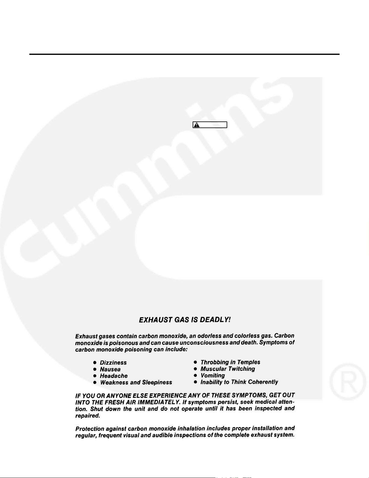
EXHAUST GASES ARE DEADLY
Provide an adequate exhaust system to properly
expel discharged gases away from enclosed or
sheltered areas and areas where individuals are
likely to congregate. Visually and audibly inspect
the exhaust daily for leaks per the maintenance
schedule. Make sure that exhaust manifolds are secured and not warped. Do not use exhaust gases to
heat a compartment.
Be sure the unit is well ventilated.
Engine exhaust and some of its constituents are
known to the state of California to cause cancer,
birth defects, and other reproductive harm.
MOVING PARTS CAN CAUSE SEVERE
PERSONAL INJURY OR DEATH
Keep your hands, clothing, and jewelry away from
moving parts.
Before starting work on the generator set, discon-
nect battery charger from its AC source, then disconnect starting batteries, negative (−) cable first.
This will prevent accidental starting.
Make sure that fasteners on the generator set are
secure. Tighten supports and clamps, keep guards
in position over fans, drive belts, etc.
Do not wear loose clothing or jewelry in the vicinity of
moving parts, or while working on electrical equipment. Loose clothing and jewelry can become
caught in moving parts.
If adjustment must be made while the unit is run-
ning, use extreme caution around hot manifolds,
moving parts, etc.
DO NOT OPERATE IN FLAMMABLE AND
EXPLOSIVE ENVIRONMENTS
Flammable vapor can cause an engine to overspeed and
become difficult to stop, resulting in possible fire, explosion, severe personal injury and death. Do not operate a
genset where a flammable vapor environment can be
created by fuel spill, leak, etc., unless the genset is
equipped with an automatic safety device to block the air
intake and stop the engine. The owners and operators of
the genset are solely responsible for operating the genset safely. Contact your authorized Onan/Cummins dealer or distributor for more information.
LS-13M
iii

ELECTRICAL SHOCK CAN CAUSE
SEVERE PERSONAL INJURY OR DEATH
Remove electric power before removing protective
shields or touching electrical equipment. Use rubber insulative mats placed on dry wood platforms
over floors that are metal or concrete when around
electrical equipment. Do not wear damp clothing
(particularly wet shoes) or allow skin surface to be
damp when handling electrical equipment. Do not
wear jewelry. Jewelry can short out electrical contacts and cause shock or burning.
Use extreme caution when working on electrical
components. High voltages can cause injury or
death. DO NOT tamper with interlocks.
Follow all applicable state and local electrical
codes. Have all electrical installations performed by
a qualified licensed electrician. Tag and lock open
switches to avoid accidental closure.
DO NOT CONNECT GENERATOR SET DIRECT-
LY TO ANY BUILDING ELECTRICAL SYSTEM.
Hazardous voltages can flow from the generator set
into the utility line. This creates a potential for electrocution or property damage. Connect only
through an approved isolation switch or an approved paralleling device.
MEDIUM VOLTAGE GENERATOR SETS
(601V to 15kV)
Medium voltage acts differently than low voltage.
Special equipment and training is required to work
on or around medium voltage equipment. Operation
and maintenance must be done only by persons
trained and qualified to work on such devices. Improper use or procedures will result in severe personal injury or death.
Do not work on energized equipment. Unauthorized
personnel must not be permitted near energized
equipment. Due to the nature of medium voltage
electrical equipment, induced voltage remains even
after the equipment is disconnected from the power
source. Plan the time for maintenance with authorized personnel so that the equipment can be de-energized and safely grounded.
GENERAL SAFETY PRECAUTIONS
Coolants under pressure have a higher boiling point
than water. DO NOT open a radiator or heat exchanger pressure cap while the engine is running.
Allow the generator set to cool and bleed the system
pressure first.
Used engine oils have been identified by some state
or federal agencies as causing cancer or reproductive toxicity. When checking or changing engine oil,
take care not to ingest, breathe the fumes, or contact used oil.
Keep multi-class ABC fire extinguishers handy.
Class A fires involve ordinary combustible materials
such as wood and cloth; Class B fires, combustible
and flammable liquid fuels and gaseous fuels; Class
C fires, live electrical equipment. (ref. NFPA No. 10).
Make sure that rags are not left on or near the en-
gine.
Make sure generator set is mounted in a manner to
prevent combustible materials from accumulating
under the unit.
Remove all unnecessary grease and oil from the
unit. Accumulated grease and oil can cause overheating and engine damage which present a potential fire hazard.
Keep the generator set and the surrounding area
clean and free from obstructions. Remove any debris from the set and keep the floor clean and dry.
Do not work on this equipment when mentally or
physically fatigued, or after consuming any alcohol
or drug that makes the operation of equipment unsafe.
Substances in exhaust gases have been identified
by some state or federal agencies as causing cancer or reproductive toxicity. Take care not to breath
or ingest or come into contact with exhaust gases.
Do not store any flammable liquids, such as fuel,
cleaners, oil, etc., near the generator set. A fire or
explosion could result.
Wear hearing protection when going near an oper-
ating generator set.
To prevent serious burns, avoid contact with hot
metal parts such as radiator, turbo charger and exhaust system.
iv
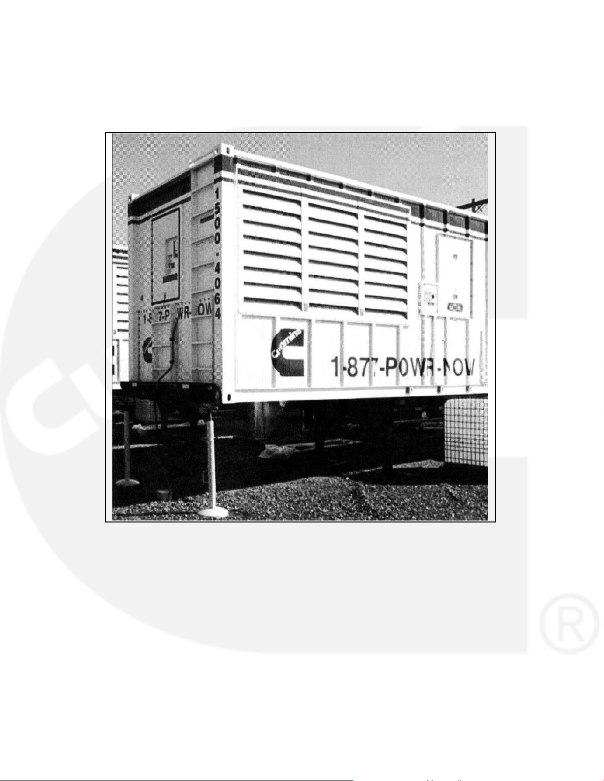
CONTAINERIZED RENTAL UNITS
POTENTIAL TIPPING PROBLEM
On all containerized rental equipment, there is a potential
problem of having the container tip forward over the landing legs, pulling the axles off the ground when the con-
tainer is fully fueled without a semi-tractor under the king
pin. Jack stands for the front of the container are required
to mitigate this potential problem.
Note: The figure below shows the jack stands and
their placement at the nose of the container.
Jack Stands at Nose of Container
KEEP THIS MANUAL NEAR THE GENSET FOR EASY REFERENCE
iii
LS-13M

THIS PAGE LEFT INTENTIONALLY BLANK
iv

1. Introduction
GENERAL
Each operator should read this manual before operating the set for the first time. A generator set (genset) must be operated and maintained properly if
you are to expect safe, reliable and quiet operation.
The manual includes a troubleshooting guide and a
maintenance schedule.
The engine manual is included with the set. Where
there is conflicting information, this manual takes
precedence over the engine manual.
WARNING
nance can lead to severe personal injury or loss
of life and property by fire, electrocution, mechanical breakdown or exhaust gas asphyxiation. Read and follow the safety precautions
on page iii and carefully observe all instructions
and precautions in this manual.
Improper operation and mainte-
HOW TO OBTAIN SERVICE
When the generator set requires servicing, contact
your nearest Cummins Power Generation distribu-
tor. Factory-trained Parts and Service representatives are ready to handle all your service needs.
To contact your local Cummins Power Generation
distributor in the United States or Canada, call
1-800-888-6626 (this automated service utilizes
touch-tone phones only). By selecting Option 1
(press 1), you will be automatically connected to the
distributor nearest you.
If you are unable to contact a distributor using the
automated service, consult the Yellow Pages. Typically, our distributors are listed under:
GENERATORS-ELECTRIC or
ELECTRICAL PRODUCTS
For outside North America, call Cummins Power
Generation, 1-763-574-5000, 7:30 AM to 4:00 PM,
Central Standard Time, Monday through Friday. Or,
send a fax to Cummins Power Generation using the
fax number 1-763-528-7229.
When contacting your distributor, always supply the
complete Model, Specification, and Serial Number
as shown on the generator set nameplate.
WARNING
INCORRECT SERVICE OR PARTS REPLACEMENT CAN RESULT IN SEVERE PERSONAL INJURY, DEATH, AND/OR EQUIPMENT DAMAGE. SERVICE PERSONNEL MUST BE TRAINED
AND EXPERIENCED TO PERFORM ELECTRICAL AND/OR MECHANICAL SERVICE.
1-1

THIS PAGE LEFT INTENTIONALLY BLANK
1-2
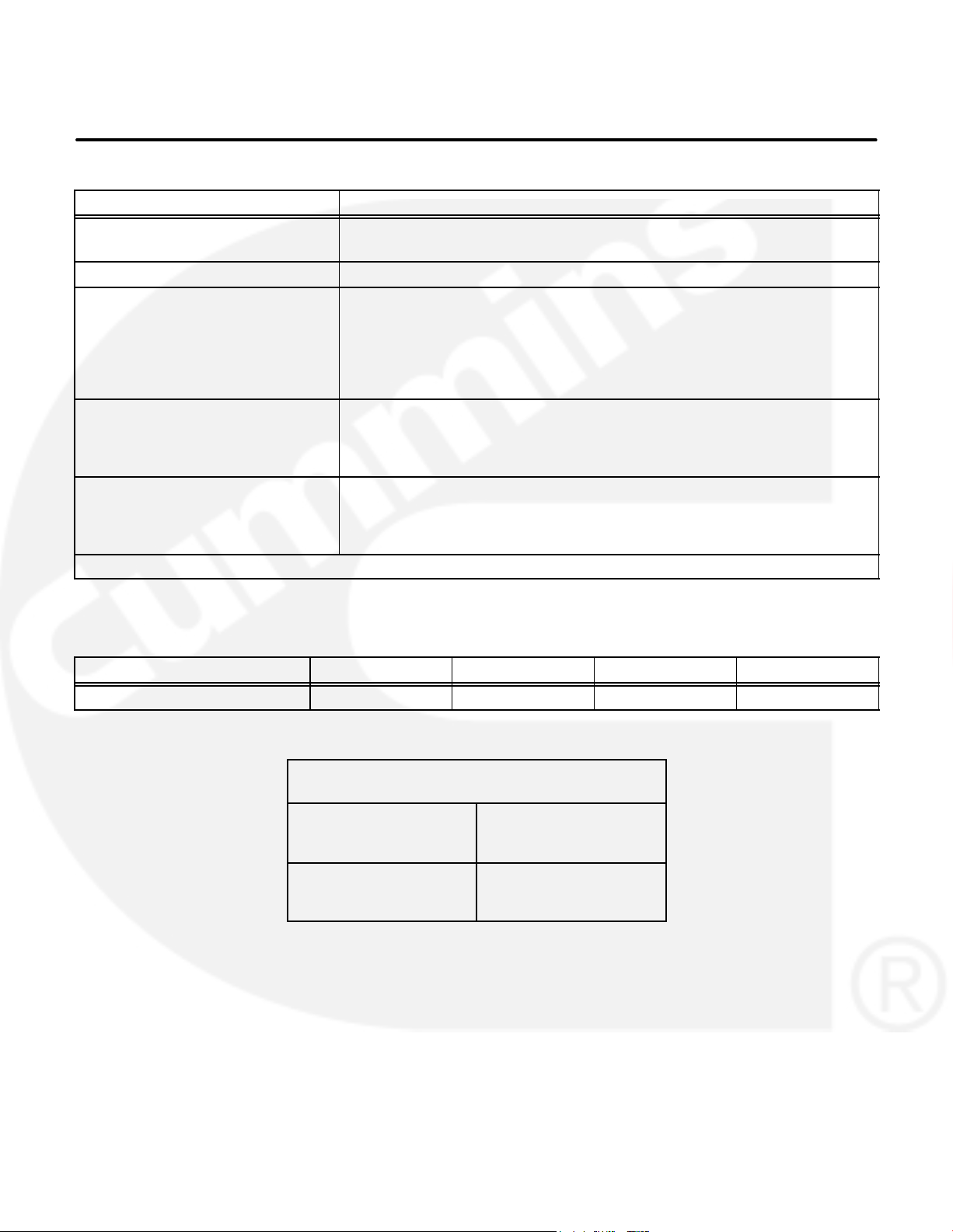
2. Specifications
MODEL DFHA, DFHB, DFHC, DFHD
Engine
Cummins Diesel Series
Generator (Standby Rating) See Genset Nameplate for rating information.
Electrical System
Starting Voltage
Battery
Group Number
CCA (minimum)
Cold Soak @ 0F (-18 C)
Cooling System
Engine and Radiator
104 F (40 C)
122 F (50 C)
Lubricating System
Oil Capacity with Filters
Oil Type*
* Refer to Cummins engine Operation and Maintenance Manual for lubricating oil recommendations/specifications.
QST30
24 Volts DC
Two, 12 Volt
8D
1400
53 Gal (201 L)
57 Gal (216 L)
35 Gal (132 L)
FUEL CONSUMPTION (STANDBY/FULL LOAD/60HZ)
MODEL
US gph (L/hr) 54.7 (207.3) 57.8 (219.1) 60.2 (228.2) 69.3 (262.6)
Normal Oil Pressure
Idle Oil Pressure
DFHA DFHB DFHC DFHD
OIL PRESSURE WARNING AND
SHUTDOWN LIMITS (PCC ONLY)
45-65 psi (310-448 kPa)
Warning Limit
Shutdown Limit
Warning Limit
Shutdown Limit
40 psi (276 kPa)
35 psi (241 kPa)
20 psi (138 kPa)
15 psi (103 kPa)
10 psi (69 kPa)
2-1

THIS PAGE LEFT INTENTIONALLY BLANK
2-2
3. Operation
GENERAL
The following describes the function and operation
of the PowerCommand
dicators, displays, meters and control switches are
located on the face of the control panel as illustrated
in Figure 3-1.
This section covers prestart checks, starting and
stopping and operating the generator set. Each operator should read through this entire section before
attempting to start the set. It is essential that the operator be completely familiar with the set and the
PCC control. Refer to Section 7 for operating rec-
ommendations.
Control 3100 (PCC). All in-
PRESTART CHECKS
Before starting, be sure the following checks have
been made and the unit is ready for operation.
Lubrication
Check the engine oil level. Keep the oil level near as
possible to the dipstick high mark without overfilling.
Coolant
Check the engine coolant level. The coolant should
be about 3/4 inch (18 mm) below the radiator cap
lower sealing surface. Do not check while the engine is hot.
WARNING
gine cool down before removing coolant pressure cap. Turn cap slowly, and do not open it fully until the pressure has been relieved.
To prevent severe scalding, let en-
Fuel
Make sure the fuel tanks have sufficient fuel and
that fuel system is primed. Check to make sure
there are no leaks and that all fittings are tight.
Exhaust
Check to make sure entire exhaust system is tight,
that no combustible materials are near system, and
gases are discharged away from building openings.
3-1

PCC POWER ON / STANDBY MODE
The control panel can be set to function in one of the
following modes; Power On or Standby.
To select the alternate mode, refer to the Installation
manual.
Power On Mode: In this mode, power is continu-
ously supplied to the control panel. The control’s
operating software and control panel LED’s/display
will remain active.
Standby Mode: In this mode, the control’s operating software is inactive and the LED’s and displays
on the front panel are all off. The operating software
is initialized and the front panel is turned on in response to one of the following:
moving the Run/Off/Auto switch to the Run
position,
pressing the Self Test button,
a remote start input signal (generator set in
Auto mode), or
any one of several “wake-up” signals from ex-
ternal switches.
The wake up signals are:
Low Engine Coolant Level
Low Engine Coolant Temperature
Low Fuel
Customer Fault Inputs 2 and 3
Run Selected on Run/Off Auto Switch
Remote Start Signal in Auto Mode
Emergency Stop
With the switch set to Standby mode, pressing the
Self Test button will allow you to activate and view
the menu displays without starting the generator
set. If no menu selections are made, a software timer will shut down the power after 30 seconds.
When left in the Standby mode, and a “Warning”
signal is sensed by the PCC (for example, low coolant temp), the control will wake up and display the
warning message. The control will remain active
until the warning condition is corrected and the Reset button is pressed to clear the warning message.
3-2
KILOWATT
METER
(PERCENT LOAD)
FREQUENCY
METER
AC
VOLTMETER
AC AMMETER
MENU
SELECTION
SWITCH
(1 of 4)
ACTIVE SWITCH
INDICATOR
(1 of 6)
ALPHANUMERIC
DISPLAY
UPPER AND LOWER
SCALE INDICATOR
PCC 3100
LABEL
RUN/OFF/AUTO
SWITCH
SELF TEST
SWITCH
NON-AUTOMATIC
WARNING
SHUTDOWN
STATUS INDICATORS
RESET
SWITCH
MENU
SWITCH
FIGURE 3-1. FRONT PANEL (PCC 3100)
3-3
PANEL LAMP
SWITCH
PHASE SELECTOR
SWITCH AND
INDICATORS
EMERGENCY
STOP PUSH
BUTTON

FRONT PANEL
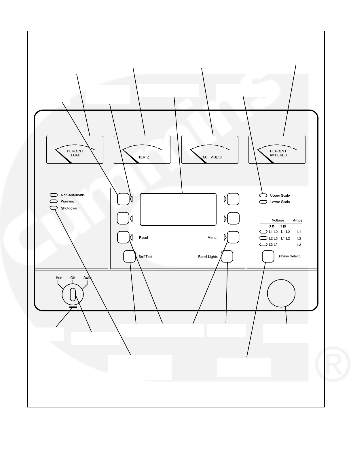
Figure 3-1 shows the features of the front panel.
Self Test Switch: Press and hold this switch to light
all front panel LEDs and cycle through all shutdown
and warning messages.
AC Voltmeter: Dual scale instrument indicates AC
voltage. Measurement scale in use is shown on
scale indicator lamp.
AC Ammeter: Indicates current output in percent of
maximum rated current.
Kilowatt Meter: Indicates 3-phase AC power output as percent of rated load.
Frequency Meter: Indicates generator output frequency in hertz.
Upper and Lower Scale Indicator Lamps: Indicate AC voltmeter scale.
Digital Display: This two-line, 16-character per line
alphanumeric display is used in the menu-driven
operating system, in conjunction with the display
menu selection switches and the Menu switch. Refer to the menu trees later in this section. The display is also used to show warning and shutdown
messages.
Display Menu Selection Switches: Four momentary switches—two on each side of the digital display window—are used to step through the various
menu options and to adjust generator set parameters. The green arrow adjacent to the switch is lit
when the switch can be used (switch is “active”).
Menu Switch: Press this switch to return the digital
display to the MAIN MENU. Refer to the menu trees
later in this section.
Reset Switch: Press this switch to reset warning
and shutdown messages after the condition has
been corrected. To reset a shutdown message with
the Reset switch, the Run/Off/Auto switch must be
in the Off position.
In Auto mode, shutdown faults can be reset by removing the remote start input and then cycling the
remote reset input.
Panel Lights Switch: Press this switch to turn control panel illumination on and off. The illumination
will shut off after about eight minutes.
Phase Selector Switch and Indicators: Press this
momentary switch to select phases of generator
output to be measured by AC voltmeter and ammeter. LEDs indicate the selected phase.
Run/Off/Auto Switch: This switch starts and stops
the set locally, or enables start/stop control of the
engine from a remote location. (Ground to start.)
Emergency Stop Button: Push the switch in for
emergency shutdown of the engine.
To reset:
Pull the button out or turn the button clockwise
(button with arrow) and allow it to pop out. Move
the Run/Off/Auto switch to Off.
Press the front panel Reset switch.
Select Run or Auto, as required.
Non-Automatic Status Indicator: This red lamp
flashes continuously when the Run/Off/Auto switch
is not in the Auto position.
Warning Status Indicator: This yellow lamp is lit
whenever the control detects a warning condition.
After the condition is corrected, warning indicators
can be reset by pressing the Reset switch. (It is not
necessary to stop the generator set.) In auto mode,
warning indicators can also be reset by cycling the
remote reset input after the condition is corrected.
Shutdown Status Indicator: This red lamp is lit
whenever the control detects a shutdown condition.
After the condition is corrected, shutdown indicators can be reset by turning the Run/Off/Auto switch
to the Off position, and pressing the Reset switch. In
auto mode, shutdown faults can be reset by removing the remote start input and then cycling the remote reset input.
Emergency Stop shutdown status (Code 102) can be
reset only at the PCC front panel.
3-4

STARTING
Automatic Starting from ATS
The following sections cover the three systems
used to start the generator set.
Before starting the generator set, make sure that
exhaust and fuel fittings are tight and properly positioned and that proper maintenance has been performed. See Prestart Checks in this section.
Starting at Control Panel
Move the Run/Off/Auto switch to the Run position.
This will activate the engine control system and the
starting system. The starter will begin cranking, and
after a few seconds the engine will start and the
starter will disconnect.
If the engine does not start, the starter will disengage after a specified period of time and the control
will indicate an overcrank shutdown.
Generator sets with the cycle cranking option selected will alternately crank and rest for 3, 4, or 5
cycles. The crank times and rest times can be individually preset for 7 to 20 seconds.
To change the cycle number, and the crank and rest
times, contact an authorized service center.
Generator sets with the cycle cranking option not
selected will crank continuously for up to 75 seconds before disengaging the starter.
To clear an overcrank shutdown, place the Run/Off/
Auto switch in the Off position and momentarily
press the Reset switch. Wait two minutes for the
starter motor to cool and then repeat the starting
procedure. If the engine does not run after a second
attempt, refer to the Troubleshooting section.
Starting from Remote Location
Place the Run/Off/Auto switch in the Auto position.
This allows the generator set to be started from a remote switch.
The operating software is initialized and the front
panel is turned on in response to a remote run signal. Closing the remote switch initiates the starting
sequence described in the previous section.
Starter cranking will begin after the start time delay
timer (0−300 seconds) has timed out. Refer to Time
Delay Start in the Adjust menu.
Place the Run/Off/Auto switch in the Auto position if
an automatic transfer switch (ATS) is used. The operating software is initialized in response to a remote run signal from the transfer switch. This allows
the transfer switch to start the generator set if a power outage occurs and stop it when the power returns.
Starter cranking will begin after the start time delay
timer (0−300 seconds) has timed out. Refer to Time
Delay Start in the Adjust menu.
Cold Starting with Loads
In accordance with NFPA 110, Cummins Power
Generation recommends installing diesel standby
generator sets (life safety systems) equipped with
engine jacket water coolant heaters in locations
where the minimum ambient temperature is above
40
F (4C). NFPA also requires that the engine be
heated as necessary to maintain the water jacket
temperature determined by the manufacturer for
cold start and load acceptance for the type of system. Although most Cummins Power Generation
generator sets will start in temperatures down to
−25
F (−32C) when equipped with engine jacket
water coolant heaters, it might take more than 10
seconds to warm the engine before a load can be
applied when ambient temperatures are below
40
F (4C).
On generator sets equipped with a graphic display,
the Low Coolant Temperature (Code 210) mes-
sage, in conjunction with illumination of the Warning
LED, is provided to meet the requirements of NFPA
110. The engine cold sensing logic initiates a warning when the engine jacket water coolant temperature falls below 70
the ambient temperature falls below 40
cold engine may be indicated even though the coolant heaters are connected and operating correctly.
Under these conditions, although the generator set
may start, it may not be able to accept load within 10
seconds. When this condition occurs, check the
coolant heaters for proper operation. If the coolant
heaters are operating properly, other precautions
may be necessary to warm the engine before applying a load.
F (21C). In applications where
F (4C), a
3-5

STOPPING
Before Stopping
Run the generator set at no load for three to five
minutes before stopping. This allows the lubricating
oil and engine coolant to carry heat away from the
combustion chamber and bearings.
Stopping at Control Panel
If the set was started at the set control panel, move
the Run/Off/Auto switch to the Off position. The set
will stop immediately. The control will respond to
“wake up” signals from the external sensing
switches when the Run/Off/Auto switch is in the Off
position.
Stopping from Remote Location
Move the remote starting switch to the Off position.
The set will stop after the stop time delay timer
(0−600 seconds) has timed out. Refer to Time Delay
Stop in the Adjust menu.
Automatic Stopping from ATS
If the set was started by an automatic transfer
switch, the transfer switch control will send a remote
stop signal after the normal power source returns.
To reset, pull the button out or turn the button clockwise (button with arrow) and allow it to pop out.
Move the Run/Off/Auto switch to the Off position.
Then momentarily push the Reset switch.
Emergency Stop shutdown status can be reset only
at the PCC front panel.
CUSTOMER INPUTS
Remote Start Input: When the Run/Off/Auto
switch is in the Auto position, selecting this input initiates the engine cranking and start sequence.
Remote Reset Input: When the Run/Off/Auto
switch is in the Auto position and the remote start
switch is open, selecting this input resets any
latched shutdown fault (except Emergency Stop,
which must be reset at the front panel.)
Engine Idle Input: When the set is operating in the
RUN mode, selecting this input causes generator
build up to be inhibited and the engine to be governed at 800 RPM. When ground is removed from
this input, the set returns to normal speed and voltage.
Engine idle operation is applicable only in the RUN
mode. The PCC operating program does not permit
engine idle operation when the set is operating in
AUTO mode.
The set will stop after the stop time delay timer
(0−600 seconds) has timed out. Refer to Time Delay
Stop in the Adjust menu.
Emergency Stop (Code 102)
The emergency stop button is located on the lower
right side of control panel (Figure 3-1). Push the button in for emergency stop. The red Shutdown status
LED will light, and the digital display message will
be: “EMERGENCY STOP
102 − SHUTDOWN”
When the engine idle function is enabled, the control automatically sets lower oil pressure warning
and shutdown trip points to reflect the lower operating speed. When the engine idle function is removed and the set reverts to normal operating
speed, the control automatically resets oil pressure
warning and shutdown trip points to the normal settings.
Remote Emergency Stop Input: Grounding this
input causes an immediate shutdown. Emergency
stop must be reset at the front panel.
3-6
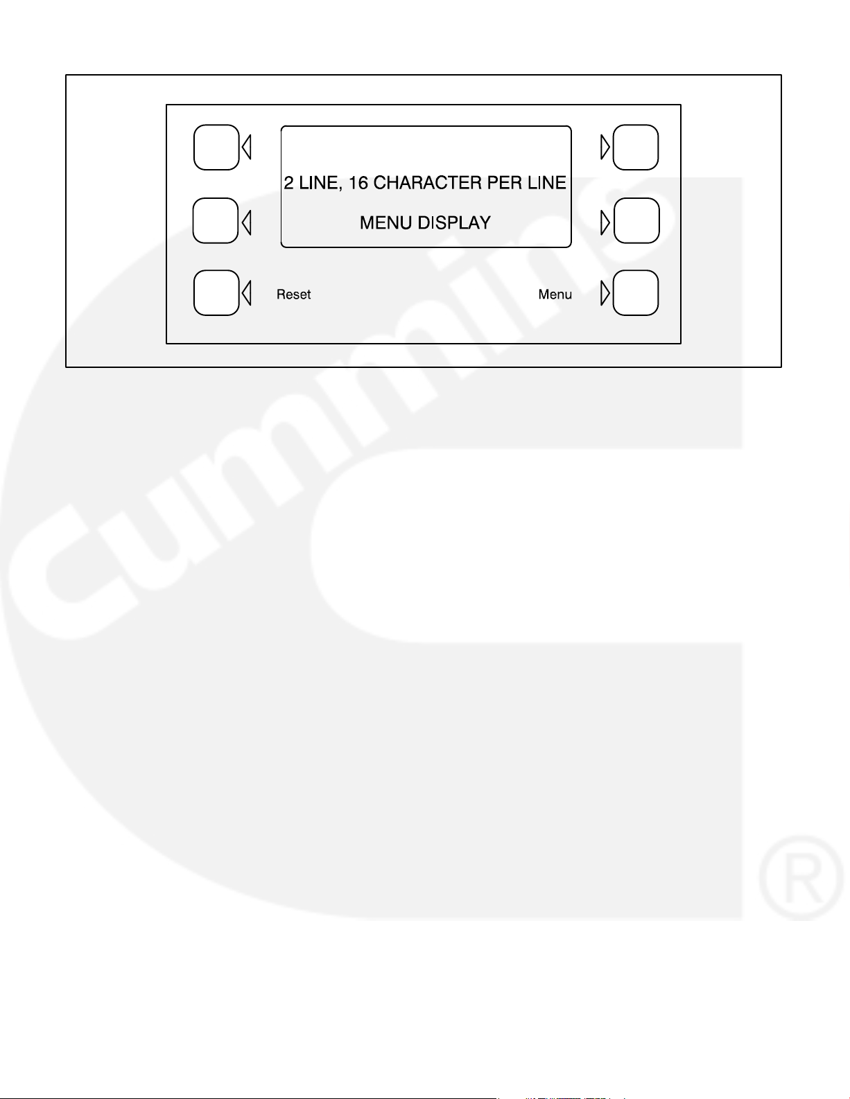
FIGURE 3-2. DIGITAL DISPLAY AND MENU SELECTION SWITCHES
MENU DISPLAY AND SWITCHES
Figure 3-2 shows the digital display and the menu
selection switches.
In Standby Mode, to activate and view the menu displays without starting the generator set, press and
release the Self Test switch. This will initialize the
PCC operating software and permit operation of the
menu display panel. If no menu selections are made,
a software timer will shut down the display power after 30 seconds. In Power On Mode, power is continuously supplied to the control panel. Display will always remain active.
Digital Display: This two-line, 16-character per line
alphanumeric display is used in the menu-driven
operating system, in conjunction with the display
menu selection switches and the Menu switch.
Display Menu Selection Switches: Four momentary switches—two on each side of the digital dis-
play window—are used to step through the various
menu options and to adjust generator set parameters. The green arrow adjacent to the switch is lit
when the switch is available for use (is active).
Menu Switch: Press this momentary switch to return the digital display to the main menu. (Refer to
the main menu diagram on the next page.
Reset Switch: Press this momentary switch to reset warning and shutdown messages after the condition has been corrected.
In the digital display, the “>>” symbol indicates that
selecting the adjacent button causes the operating
program to branch to the next menu display—as
shown in the menu diagrams.
In the digital display, the “<<” symbol indicates that
selecting the adjacent button causes the operating
program to go back to the previous menu display.
3-7
 Loading...