

Operator Manual
Generator Set
with PowerCommandR 3100 Controller
DFHA (Spec A−J)
DFHB (Spec A−J)
DFHC (Spec A−J)
DFHD (Spec A−J)
English−Original Instructions 11-2011 960-0106 (Issue 9)


Table of Contents
SECTION TITLE PAGE
IMPORTANT SAFETY INSTRUCTIONS iii. . . . . . . . . . . . . . . . . . . . . . . . . . . . . . .
1 INTRODUCTION 1-1. . . . . . . . . . . . . . . . . . . . . . . . . . . . . . . . . . . . . . . . . . . . . . . . . .
General 1-1. . . . . . . . . . . . . . . . . . . . . . . . . . . . . . . . . . . . . . . . . . . . . . . . . . . . . . . .
How to Obtain Service 1-1. . . . . . . . . . . . . . . . . . . . . . . . . . . . . . . . . . . . . . . . . . .
2 SPECIFICATIONS 2-1. . . . . . . . . . . . . . . . . . . . . . . . . . . . . . . . . . . . . . . . . . . . . . . . .
3 OPERATION 3-1. . . . . . . . . . . . . . . . . . . . . . . . . . . . . . . . . . . . . . . . . . . . . . . . . . . . . .
General 3-1. . . . . . . . . . . . . . . . . . . . . . . . . . . . . . . . . . . . . . . . . . . . . . . . . . . . . . . .
Prestart Checks 3-1. . . . . . . . . . . . . . . . . . . . . . . . . . . . . . . . . . . . . . . . . . . . . . . . .
PCC Power On / Standby Mode 3-2. . . . . . . . . . . . . . . . . . . . . . . . . . . . . . . . . . .
Front Panel 3-4. . . . . . . . . . . . . . . . . . . . . . . . . . . . . . . . . . . . . . . . . . . . . . . . . . . . .
Starting 3-5. . . . . . . . . . . . . . . . . . . . . . . . . . . . . . . . . . . . . . . . . . . . . . . . . . . . . . . .
Stopping 3-6. . . . . . . . . . . . . . . . . . . . . . . . . . . . . . . . . . . . . . . . . . . . . . . . . . . . . . .
Customer Inputs 3-6. . . . . . . . . . . . . . . . . . . . . . . . . . . . . . . . . . . . . . . . . . . . . . . . .
Menu Display and Switches 3-7. . . . . . . . . . . . . . . . . . . . . . . . . . . . . . . . . . . . . . .
Main Menu 3-8. . . . . . . . . . . . . . . . . . . . . . . . . . . . . . . . . . . . . . . . . . . . . . . . . . . . .
ENGINE Menu 3-10. . . . . . . . . . . . . . . . . . . . . . . . . . . . . . . . . . . . . . . . . . . . . . . . .
GEN Menu 3-12. . . . . . . . . . . . . . . . . . . . . . . . . . . . . . . . . . . . . . . . . . . . . . . . . . . .
ADJUST Menu 3-14. . . . . . . . . . . . . . . . . . . . . . . . . . . . . . . . . . . . . . . . . . . . . . . . .
VERSION Menu 3-16. . . . . . . . . . . . . . . . . . . . . . . . . . . . . . . . . . . . . . . . . . . . . . . .
4 TROUBLESHOOTING 4-1. . . . . . . . . . . . . . . . . . . . . . . . . . . . . . . . . . . . . . . . . . . . .
Safety Considerations 4-1. . . . . . . . . . . . . . . . . . . . . . . . . . . . . . . . . . . . . . . . . . . .
Status Indicators 4-2. . . . . . . . . . . . . . . . . . . . . . . . . . . . . . . . . . . . . . . . . . . . . . . .
Resetting The Control 4-2. . . . . . . . . . . . . . . . . . . . . . . . . . . . . . . . . . . . . . . . . . . .
Warning and Shutdown Codes Table 4-3. . . . . . . . . . . . . . . . . . . . . . . . . . . . . . .
Troubleshooting Tables 4-4. . . . . . . . . . . . . . . . . . . . . . . . . . . . . . . . . . . . . . . . . . .
California
Proposition 65 Warning
Diesel engine exhaust and some of its constituents are known
to the State of California to cause cancer, birth defects, and
other reproductive harm.
i

SECTION TITLE PAGE
5 MAINTENANCE
General 5-1. . . . . . . . . . . . . . . . . . . . . . . . . . . . . . . . . . . . . . . . . . . . . . . . . . . . . . . .
Maintenance Schedule 5-2. . . . . . . . . . . . . . . . . . . . . . . . . . . . . . . . . . . . . . . . . . .
Generator Set Inspection 5-3. . . . . . . . . . . . . . . . . . . . . . . . . . . . . . . . . . . . . . . . .
Generator Set Maintenance (Battery Disconnected) 5-4. . . . . . . . . . . . . . . . . .
Lubrication System 5-5. . . . . . . . . . . . . . . . . . . . . . . . . . . . . . . . . . . . . . . . . . . . . .
Cooling System 5-6. . . . . . . . . . . . . . . . . . . . . . . . . . . . . . . . . . . . . . . . . . . . . . . . .
Air Cleaner 5-8. . . . . . . . . . . . . . . . . . . . . . . . . . . . . . . . . . . . . . . . . . . . . . . . . . . . .
Charge-Air Piping 5-8. . . . . . . . . . . . . . . . . . . . . . . . . . . . . . . . . . . . . . . . . . . . . . . .
Fuel System 5-8. . . . . . . . . . . . . . . . . . . . . . . . . . . . . . . . . . . . . . . . . . . . . . . . . . . .
Batteries 5-9. . . . . . . . . . . . . . . . . . . . . . . . . . . . . . . . . . . . . . . . . . . . . . . . . . . . . . .
P7 Generator Bearing Re-Lubrication 5-11. . . . . . . . . . . . . . . . . . . . . . . . . . . . .
6 OPTIONAL ENCLOSURE FEATURES
General 6-1 . . . . . . . . . . . . . . . . . . . . . . . . . . . . . . . . . . . . . . . . . . . . . . . . . . . . . . .
External Receptacle 6-1 . . . . . . . . . . . . . . . . . . . . . . . . . . . . . . . . . . . . . . . . . . . .
External/Internal Alarm Panels 6-2 . . . . . . . . . . . . . . . . . . . . . . . . . . . . . . . . . . .
External Emergency Stop Switch 6-3 . . . . . . . . . . . . . . . . . . . . . . . . . . . . . . . . .
AC Distribution Panel 6-4 . . . . . . . . . . . . . . . . . . . . . . . . . . . . . . . . . . . . . . . . . . .
Fuel Transfer Pump 6-5 . . . . . . . . . . . . . . . . . . . . . . . . . . . . . . . . . . . . . . . . . . . . .
7 OPERATING RECOMMENDATION
No-Load Operation 7-1. . . . . . . . . . . . . . . . . . . . . . . . . . . . . . . . . . . . . . . . . . . . . .
Exercise Period 7-1. . . . . . . . . . . . . . . . . . . . . . . . . . . . . . . . . . . . . . . . . . . . . . . . .
Low Operating Temperature 7-1. . . . . . . . . . . . . . . . . . . . . . . . . . . . . . . . . . . . . .
High Operating Temperature 7-1. . . . . . . . . . . . . . . . . . . . . . . . . . . . . . . . . . . . . .
ii
IMPORTANT SAFETY INSTRUCTIONS
SAVE THESE INSTRUCTIONS − This manual contains
important instructions that should be followed during
installation and maintenance of the generator and batteries.
Before operating the generator set (genset), read the
Operator’s Manual and become familiar with it and the
equipment. Safe and efficient operation can be
achieved only if the equipment is properly operated
and maintained. Many accidents are caused by failure
to follow fundamental rules and precautions.
The following symbols, found throughout this manual,
alert you to potentially dangerous conditions to the operator, service personnel, or the equipment.
DANGER
This symbol warns of immediate
hazards which will result in severe personal injury or death.
WARNING
This symbol refers to a hazard or
unsafe practice which can result in severe personal injury or death.
CAUTION
This symbol refers to a hazard or
unsafe practice which can result in personal injury or product or property damage.
FUEL AND FUMES ARE FLAMMABLE
Fire, explosion, and personal injury or death can result
from improper practices.
DO NOT fill fuel tanks while engine is running, un-
less tanks are outside the engine compartment.
Fuel contact with hot engine or exhaust is a potential
fire hazard.
DO NOT permit any flame, cigarette, pilot light,
spark, arcing equipment, or other ignition source
near the generator set or fuel tank.
Fuel lines must be adequately secured and free of
leaks. Fuel connection at the engine should be
made with an approved flexible line. Do not use zinc
coated or copper fuel lines with diesel fuel.
Be sure all fuel supplies have a positive shutoff
valve.
Be sure battery area has been well-ventilated prior
to servicing near it. Lead-acid batteries emit a highly
explosive hydrogen gas that can be ignited by arcing, sparking, smoking, etc.
EXHAUST GASES ARE DEADLY
Provide an adequate exhaust system to properly
expel discharged gases away from enclosed or
sheltered areas and areas where individuals are
likely to congregate. Visually and audibly inspect
the exhaust daily for leaks per the maintenance
schedule. Make sure that exhaust manifolds are secured and not warped. Do not use exhaust gases to
heat a compartment.
Be sure the unit is well ventilated.
Engine exhaust and some of its constituents are
known to the state of California to cause cancer,
birth defects, and other reproductive harm.
MOVING PARTS CAN CAUSE SEVERE
PERSONAL INJURY OR DEATH
Keep your hands, clothing, and jewelry away from
moving parts.
Before starting work on the generator set, discon-
nect battery charger from its AC source, then disconnect starting batteries, negative (−) cable first.
This will prevent accidental starting.
Make sure that fasteners on the generator set are
secure. Tighten supports and clamps, keep guards
in position over fans, drive belts, etc.
Do not wear loose clothing or jewelry in the vicinity of
moving parts, or while working on electrical equipment. Loose clothing and jewelry can become
caught in moving parts.
If adjustment must be made while the unit is run-
ning, use extreme caution around hot manifolds,
moving parts, etc.
DO NOT OPERATE IN FLAMMABLE AND
EXPLOSIVE ENVIRONMENTS
Flammable vapor can cause an engine to overspeed and
become difficult to stop, resulting in possible fire, explosion, severe personal injury and death. Do not operate a
genset where a flammable vapor environment can be
created by fuel spill, leak, etc., unless the genset is
equipped with an automatic safety device to block the air
intake and stop the engine. The owners and operators of
the genset are solely responsible for operating the genset safely. Contact your authorized Onan/Cummins dealer or distributor for more information.
LS-13M
iii

ELECTRICAL SHOCK CAN CAUSE
SEVERE PERSONAL INJURY OR DEATH
Remove electric power before removing protective
shields or touching electrical equipment. Use rubber insulative mats placed on dry wood platforms
over floors that are metal or concrete when around
electrical equipment. Do not wear damp clothing
(particularly wet shoes) or allow skin surface to be
damp when handling electrical equipment. Do not
wear jewelry. Jewelry can short out electrical contacts and cause shock or burning.
Use extreme caution when working on electrical
components. High voltages can cause injury or
death. DO NOT tamper with interlocks.
Follow all applicable state and local electrical
codes. Have all electrical installations performed by
a qualified licensed electrician. Tag and lock open
switches to avoid accidental closure.
DO NOT CONNECT GENERATOR SET DIRECT-
LY TO ANY BUILDING ELECTRICAL SYSTEM.
Hazardous voltages can flow from the generator set
into the utility line. This creates a potential for electrocution or property damage. Connect only
through an approved isolation switch or an approved paralleling device.
MEDIUM VOLTAGE GENERATOR SETS
(601V to 15kV)
Medium voltage acts differently than low voltage.
Special equipment and training is required to work
on or around medium voltage equipment. Operation
and maintenance must be done only by persons
trained and qualified to work on such devices. Improper use or procedures will result in severe personal injury or death.
Do not work on energized equipment. Unauthorized
personnel must not be permitted near energized
equipment. Due to the nature of medium voltage
electrical equipment, induced voltage remains even
after the equipment is disconnected from the power
source. Plan the time for maintenance with authorized personnel so that the equipment can be de-energized and safely grounded.
GENERAL SAFETY PRECAUTIONS
Coolants under pressure have a higher boiling point
than water. DO NOT open a radiator or heat exchanger pressure cap while the engine is running.
Allow the generator set to cool and bleed the system
pressure first.
Used engine oils have been identified by some state
or federal agencies as causing cancer or reproductive toxicity. When checking or changing engine oil,
take care not to ingest, breathe the fumes, or contact used oil.
Keep multi-class ABC fire extinguishers handy.
Class A fires involve ordinary combustible materials
such as wood and cloth; Class B fires, combustible
and flammable liquid fuels and gaseous fuels; Class
C fires, live electrical equipment. (ref. NFPA No. 10).
Make sure that rags are not left on or near the en-
gine.
Make sure generator set is mounted in a manner to
prevent combustible materials from accumulating
under the unit.
Remove all unnecessary grease and oil from the
unit. Accumulated grease and oil can cause overheating and engine damage which present a potential fire hazard.
Keep the generator set and the surrounding area
clean and free from obstructions. Remove any debris from the set and keep the floor clean and dry.
Do not work on this equipment when mentally or
physically fatigued, or after consuming any alcohol
or drug that makes the operation of equipment unsafe.
Substances in exhaust gases have been identified
by some state or federal agencies as causing cancer or reproductive toxicity. Take care not to breath
or ingest or come into contact with exhaust gases.
Do not store any flammable liquids, such as fuel,
cleaners, oil, etc., near the generator set. A fire or
explosion could result.
Wear hearing protection when going near an oper-
ating generator set.
To prevent serious burns, avoid contact with hot
metal parts such as radiator, turbo charger and exhaust system.
iv
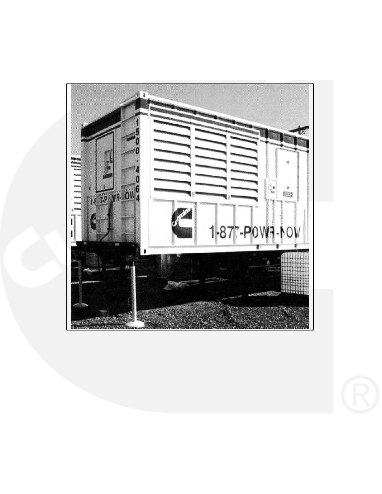
CONTAINERIZED RENTAL UNITS
POTENTIAL TIPPING PROBLEM
On all containerized rental equipment, there is a potential
problem of having the container tip forward over the landing legs, pulling the axles off the ground when the con-
tainer is fully fueled without a semi-tractor under the king
pin. Jack stands for the front of the container are required
to mitigate this potential problem.
Note: The figure below shows the jack stands and
their placement at the nose of the container.
Jack Stands at Nose of Container
KEEP THIS MANUAL NEAR THE GENSET FOR EASY REFERENCE
iii
LS-13M

THIS PAGE LEFT INTENTIONALLY BLANK
iv

1. Introduction
GENERAL
Each operator should read this manual before operating the set for the first time. A generator set (genset) must be operated and maintained properly if
you are to expect safe, reliable and quiet operation.
The manual includes a troubleshooting guide and a
maintenance schedule.
The engine manual is included with the set. Where
there is conflicting information, this manual takes
precedence over the engine manual.
WARNING
nance can lead to severe personal injury or loss
of life and property by fire, electrocution, mechanical breakdown or exhaust gas asphyxiation. Read and follow the safety precautions
on page iii and carefully observe all instructions
and precautions in this manual.
Improper operation and mainte-
HOW TO OBTAIN SERVICE
When the generator set requires servicing, contact
your nearest Cummins Power Generation distribu-
tor. Factory-trained Parts and Service representatives are ready to handle all your service needs.
To contact your local Cummins Power Generation
distributor in the United States or Canada, call
1-800-888-6626 (this automated service utilizes
touch-tone phones only). By selecting Option 1
(press 1), you will be automatically connected to the
distributor nearest you.
If you are unable to contact a distributor using the
automated service, consult the Yellow Pages. Typically, our distributors are listed under:
GENERATORS-ELECTRIC or
ELECTRICAL PRODUCTS
For outside North America, call Cummins Power
Generation, 1-763-574-5000, 7:30 AM to 4:00 PM,
Central Standard Time, Monday through Friday. Or,
send a fax to Cummins Power Generation using the
fax number 1-763-528-7229.
When contacting your distributor, always supply the
complete Model, Specification, and Serial Number
as shown on the generator set nameplate.
WARNING
INCORRECT SERVICE OR PARTS REPLACEMENT CAN RESULT IN SEVERE PERSONAL INJURY, DEATH, AND/OR EQUIPMENT DAMAGE. SERVICE PERSONNEL MUST BE TRAINED
AND EXPERIENCED TO PERFORM ELECTRICAL AND/OR MECHANICAL SERVICE.
1-1

THIS PAGE LEFT INTENTIONALLY BLANK
1-2
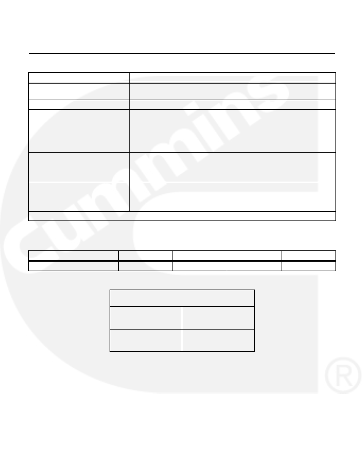
2. Specifications
MODEL DFHA, DFHB, DFHC, DFHD
Engine
Cummins Diesel Series
Generator (Standby Rating) See Genset Nameplate for rating information.
Electrical System
Starting Voltage
Battery
Group Number
CCA (minimum)
Cold Soak @ 0F (-18 C)
Cooling System
Engine and Radiator
104 F (40 C)
122 F (50 C)
Lubricating System
Oil Capacity with Filters
Oil Type*
* Refer to Cummins engine Operation and Maintenance Manual for lubricating oil recommendations/specifications.
QST30
24 Volts DC
Two, 12 Volt
8D
1400
53 Gal (201 L)
57 Gal (216 L)
35 Gal (132 L)
FUEL CONSUMPTION (STANDBY/FULL LOAD/60HZ)
MODEL
US gph (L/hr) 54.7 (207.3) 57.8 (219.1) 60.2 (228.2) 69.3 (262.6)
Normal Oil Pressure
Idle Oil Pressure
DFHA DFHB DFHC DFHD
OIL PRESSURE WARNING AND
SHUTDOWN LIMITS (PCC ONLY)
45-65 psi (310-448 kPa)
Warning Limit
Shutdown Limit
Warning Limit
Shutdown Limit
40 psi (276 kPa)
35 psi (241 kPa)
20 psi (138 kPa)
15 psi (103 kPa)
10 psi (69 kPa)
2-1

THIS PAGE LEFT INTENTIONALLY BLANK
2-2
3. Operation
GENERAL
The following describes the function and operation
of the PowerCommand
dicators, displays, meters and control switches are
located on the face of the control panel as illustrated
in Figure 3-1.
This section covers prestart checks, starting and
stopping and operating the generator set. Each operator should read through this entire section before
attempting to start the set. It is essential that the operator be completely familiar with the set and the
PCC control. Refer to Section 7 for operating rec-
ommendations.
Control 3100 (PCC). All in-
PRESTART CHECKS
Before starting, be sure the following checks have
been made and the unit is ready for operation.
Lubrication
Check the engine oil level. Keep the oil level near as
possible to the dipstick high mark without overfilling.
Coolant
Check the engine coolant level. The coolant should
be about 3/4 inch (18 mm) below the radiator cap
lower sealing surface. Do not check while the engine is hot.
WARNING
gine cool down before removing coolant pressure cap. Turn cap slowly, and do not open it fully until the pressure has been relieved.
To prevent severe scalding, let en-
Fuel
Make sure the fuel tanks have sufficient fuel and
that fuel system is primed. Check to make sure
there are no leaks and that all fittings are tight.
Exhaust
Check to make sure entire exhaust system is tight,
that no combustible materials are near system, and
gases are discharged away from building openings.
3-1

PCC POWER ON / STANDBY MODE
The control panel can be set to function in one of the
following modes; Power On or Standby.
To select the alternate mode, refer to the Installation
manual.
Power On Mode: In this mode, power is continu-
ously supplied to the control panel. The control’s
operating software and control panel LED’s/display
will remain active.
Standby Mode: In this mode, the control’s operating software is inactive and the LED’s and displays
on the front panel are all off. The operating software
is initialized and the front panel is turned on in response to one of the following:
moving the Run/Off/Auto switch to the Run
position,
pressing the Self Test button,
a remote start input signal (generator set in
Auto mode), or
any one of several “wake-up” signals from ex-
ternal switches.
The wake up signals are:
Low Engine Coolant Level
Low Engine Coolant Temperature
Low Fuel
Customer Fault Inputs 2 and 3
Run Selected on Run/Off Auto Switch
Remote Start Signal in Auto Mode
Emergency Stop
With the switch set to Standby mode, pressing the
Self Test button will allow you to activate and view
the menu displays without starting the generator
set. If no menu selections are made, a software timer will shut down the power after 30 seconds.
When left in the Standby mode, and a “Warning”
signal is sensed by the PCC (for example, low coolant temp), the control will wake up and display the
warning message. The control will remain active
until the warning condition is corrected and the Reset button is pressed to clear the warning message.
3-2
KILOWATT
METER
(PERCENT LOAD)
FREQUENCY
METER
AC
VOLTMETER
AC AMMETER
MENU
SELECTION
SWITCH
(1 of 4)
ACTIVE SWITCH
INDICATOR
(1 of 6)
ALPHANUMERIC
DISPLAY
UPPER AND LOWER
SCALE INDICATOR
PCC 3100
LABEL
RUN/OFF/AUTO
SWITCH
SELF TEST
SWITCH
NON-AUTOMATIC
WARNING
SHUTDOWN
STATUS INDICATORS
RESET
SWITCH
MENU
SWITCH
FIGURE 3-1. FRONT PANEL (PCC 3100)
3-3
PANEL LAMP
SWITCH
PHASE SELECTOR
SWITCH AND
INDICATORS
EMERGENCY
STOP PUSH
BUTTON

FRONT PANEL
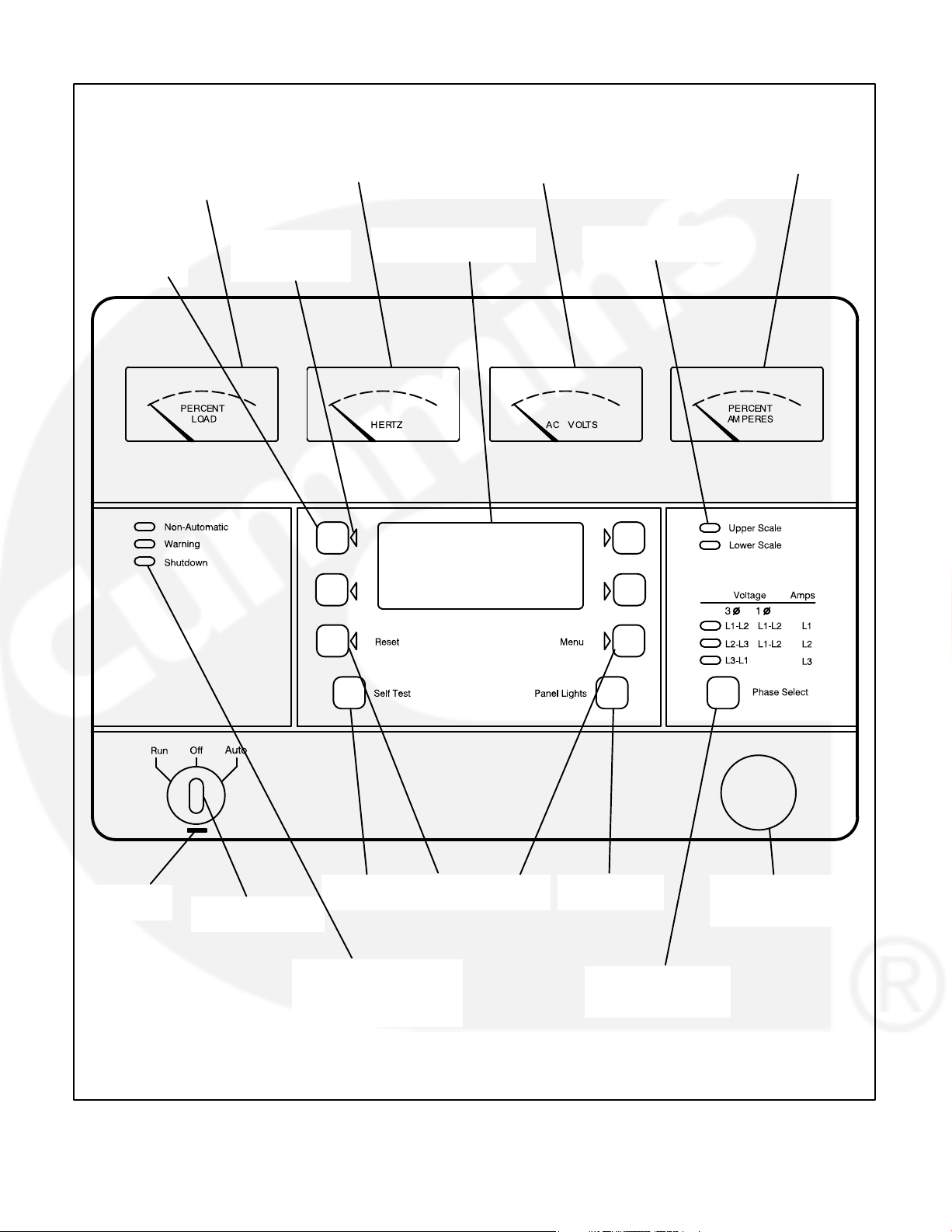
Figure 3-1 shows the features of the front panel.
Self Test Switch: Press and hold this switch to light
all front panel LEDs and cycle through all shutdown
and warning messages.
AC Voltmeter: Dual scale instrument indicates AC
voltage. Measurement scale in use is shown on
scale indicator lamp.
AC Ammeter: Indicates current output in percent of
maximum rated current.
Kilowatt Meter: Indicates 3-phase AC power output as percent of rated load.
Frequency Meter: Indicates generator output frequency in hertz.
Upper and Lower Scale Indicator Lamps: Indicate AC voltmeter scale.
Digital Display: This two-line, 16-character per line
alphanumeric display is used in the menu-driven
operating system, in conjunction with the display
menu selection switches and the Menu switch. Refer to the menu trees later in this section. The display is also used to show warning and shutdown
messages.
Display Menu Selection Switches: Four momentary switches—two on each side of the digital display window—are used to step through the various
menu options and to adjust generator set parameters. The green arrow adjacent to the switch is lit
when the switch can be used (switch is “active”).
Menu Switch: Press this switch to return the digital
display to the MAIN MENU. Refer to the menu trees
later in this section.
Reset Switch: Press this switch to reset warning
and shutdown messages after the condition has
been corrected. To reset a shutdown message with
the Reset switch, the Run/Off/Auto switch must be
in the Off position.
In Auto mode, shutdown faults can be reset by removing the remote start input and then cycling the
remote reset input.
Panel Lights Switch: Press this switch to turn control panel illumination on and off. The illumination
will shut off after about eight minutes.
Phase Selector Switch and Indicators: Press this
momentary switch to select phases of generator
output to be measured by AC voltmeter and ammeter. LEDs indicate the selected phase.
Run/Off/Auto Switch: This switch starts and stops
the set locally, or enables start/stop control of the
engine from a remote location. (Ground to start.)
Emergency Stop Button: Push the switch in for
emergency shutdown of the engine.
To reset:
Pull the button out or turn the button clockwise
(button with arrow) and allow it to pop out. Move
the Run/Off/Auto switch to Off.
Press the front panel Reset switch.
Select Run or Auto, as required.
Non-Automatic Status Indicator: This red lamp
flashes continuously when the Run/Off/Auto switch
is not in the Auto position.
Warning Status Indicator: This yellow lamp is lit
whenever the control detects a warning condition.
After the condition is corrected, warning indicators
can be reset by pressing the Reset switch. (It is not
necessary to stop the generator set.) In auto mode,
warning indicators can also be reset by cycling the
remote reset input after the condition is corrected.
Shutdown Status Indicator: This red lamp is lit
whenever the control detects a shutdown condition.
After the condition is corrected, shutdown indicators can be reset by turning the Run/Off/Auto switch
to the Off position, and pressing the Reset switch. In
auto mode, shutdown faults can be reset by removing the remote start input and then cycling the remote reset input.
Emergency Stop shutdown status (Code 102) can be
reset only at the PCC front panel.
3-4

STARTING
Automatic Starting from ATS
The following sections cover the three systems
used to start the generator set.
Before starting the generator set, make sure that
exhaust and fuel fittings are tight and properly positioned and that proper maintenance has been performed. See Prestart Checks in this section.
Starting at Control Panel
Move the Run/Off/Auto switch to the Run position.
This will activate the engine control system and the
starting system. The starter will begin cranking, and
after a few seconds the engine will start and the
starter will disconnect.
If the engine does not start, the starter will disengage after a specified period of time and the control
will indicate an overcrank shutdown.
Generator sets with the cycle cranking option selected will alternately crank and rest for 3, 4, or 5
cycles. The crank times and rest times can be individually preset for 7 to 20 seconds.
To change the cycle number, and the crank and rest
times, contact an authorized service center.
Generator sets with the cycle cranking option not
selected will crank continuously for up to 75 seconds before disengaging the starter.
To clear an overcrank shutdown, place the Run/Off/
Auto switch in the Off position and momentarily
press the Reset switch. Wait two minutes for the
starter motor to cool and then repeat the starting
procedure. If the engine does not run after a second
attempt, refer to the Troubleshooting section.
Starting from Remote Location
Place the Run/Off/Auto switch in the Auto position.
This allows the generator set to be started from a remote switch.
The operating software is initialized and the front
panel is turned on in response to a remote run signal. Closing the remote switch initiates the starting
sequence described in the previous section.
Starter cranking will begin after the start time delay
timer (0−300 seconds) has timed out. Refer to Time
Delay Start in the Adjust menu.
Place the Run/Off/Auto switch in the Auto position if
an automatic transfer switch (ATS) is used. The operating software is initialized in response to a remote run signal from the transfer switch. This allows
the transfer switch to start the generator set if a power outage occurs and stop it when the power returns.
Starter cranking will begin after the start time delay
timer (0−300 seconds) has timed out. Refer to Time
Delay Start in the Adjust menu.
Cold Starting with Loads
In accordance with NFPA 110, Cummins Power
Generation recommends installing diesel standby
generator sets (life safety systems) equipped with
engine jacket water coolant heaters in locations
where the minimum ambient temperature is above
40
F (4C). NFPA also requires that the engine be
heated as necessary to maintain the water jacket
temperature determined by the manufacturer for
cold start and load acceptance for the type of system. Although most Cummins Power Generation
generator sets will start in temperatures down to
−25
F (−32C) when equipped with engine jacket
water coolant heaters, it might take more than 10
seconds to warm the engine before a load can be
applied when ambient temperatures are below
40
F (4C).
On generator sets equipped with a graphic display,
the Low Coolant Temperature (Code 210) mes-
sage, in conjunction with illumination of the Warning
LED, is provided to meet the requirements of NFPA
110. The engine cold sensing logic initiates a warning when the engine jacket water coolant temperature falls below 70
the ambient temperature falls below 40
cold engine may be indicated even though the coolant heaters are connected and operating correctly.
Under these conditions, although the generator set
may start, it may not be able to accept load within 10
seconds. When this condition occurs, check the
coolant heaters for proper operation. If the coolant
heaters are operating properly, other precautions
may be necessary to warm the engine before applying a load.
F (21C). In applications where
F (4C), a
3-5

STOPPING
Before Stopping
Run the generator set at no load for three to five
minutes before stopping. This allows the lubricating
oil and engine coolant to carry heat away from the
combustion chamber and bearings.
Stopping at Control Panel
If the set was started at the set control panel, move
the Run/Off/Auto switch to the Off position. The set
will stop immediately. The control will respond to
“wake up” signals from the external sensing
switches when the Run/Off/Auto switch is in the Off
position.
Stopping from Remote Location
Move the remote starting switch to the Off position.
The set will stop after the stop time delay timer
(0−600 seconds) has timed out. Refer to Time Delay
Stop in the Adjust menu.
Automatic Stopping from ATS
If the set was started by an automatic transfer
switch, the transfer switch control will send a remote
stop signal after the normal power source returns.
To reset, pull the button out or turn the button clockwise (button with arrow) and allow it to pop out.
Move the Run/Off/Auto switch to the Off position.
Then momentarily push the Reset switch.
Emergency Stop shutdown status can be reset only
at the PCC front panel.
CUSTOMER INPUTS
Remote Start Input: When the Run/Off/Auto
switch is in the Auto position, selecting this input initiates the engine cranking and start sequence.
Remote Reset Input: When the Run/Off/Auto
switch is in the Auto position and the remote start
switch is open, selecting this input resets any
latched shutdown fault (except Emergency Stop,
which must be reset at the front panel.)
Engine Idle Input: When the set is operating in the
RUN mode, selecting this input causes generator
build up to be inhibited and the engine to be governed at 800 RPM. When ground is removed from
this input, the set returns to normal speed and voltage.
Engine idle operation is applicable only in the RUN
mode. The PCC operating program does not permit
engine idle operation when the set is operating in
AUTO mode.
The set will stop after the stop time delay timer
(0−600 seconds) has timed out. Refer to Time Delay
Stop in the Adjust menu.
Emergency Stop (Code 102)
The emergency stop button is located on the lower
right side of control panel (Figure 3-1). Push the button in for emergency stop. The red Shutdown status
LED will light, and the digital display message will
be: “EMERGENCY STOP
102 − SHUTDOWN”
When the engine idle function is enabled, the control automatically sets lower oil pressure warning
and shutdown trip points to reflect the lower operating speed. When the engine idle function is removed and the set reverts to normal operating
speed, the control automatically resets oil pressure
warning and shutdown trip points to the normal settings.
Remote Emergency Stop Input: Grounding this
input causes an immediate shutdown. Emergency
stop must be reset at the front panel.
3-6
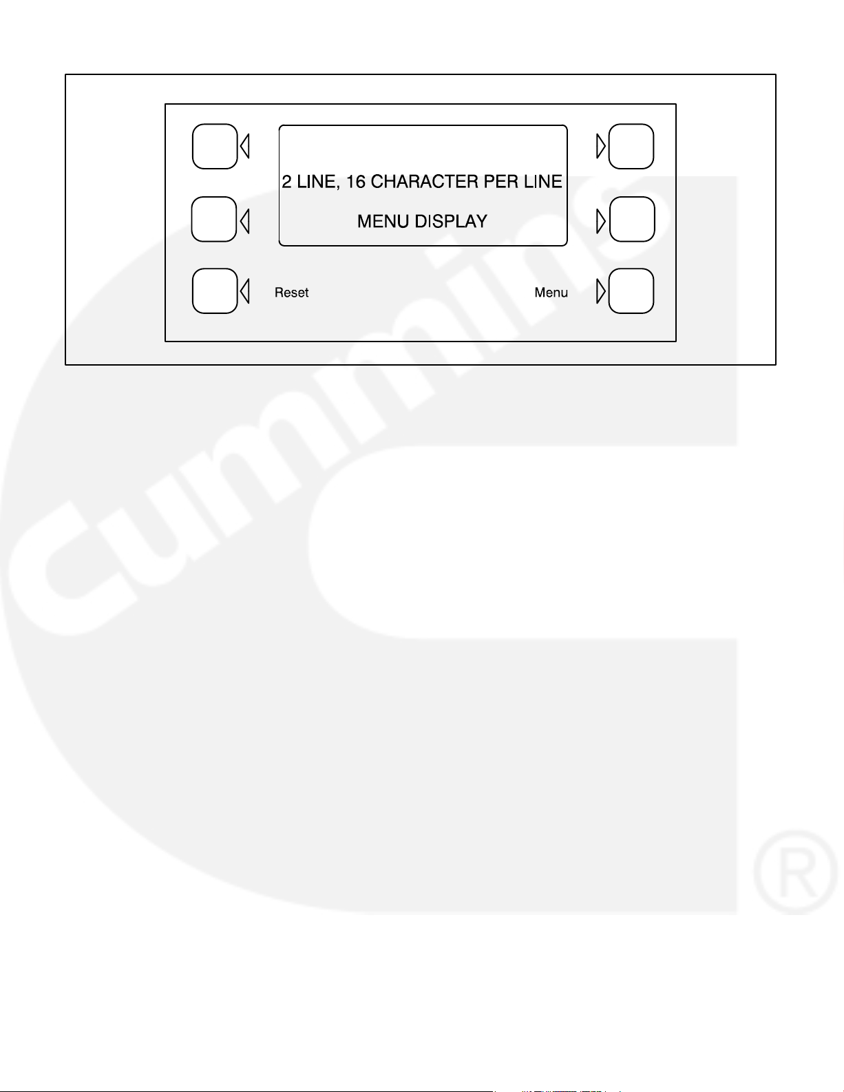
FIGURE 3-2. DIGITAL DISPLAY AND MENU SELECTION SWITCHES
MENU DISPLAY AND SWITCHES
Figure 3-2 shows the digital display and the menu
selection switches.
In Standby Mode, to activate and view the menu displays without starting the generator set, press and
release the Self Test switch. This will initialize the
PCC operating software and permit operation of the
menu display panel. If no menu selections are made,
a software timer will shut down the display power after 30 seconds. In Power On Mode, power is continuously supplied to the control panel. Display will always remain active.
Digital Display: This two-line, 16-character per line
alphanumeric display is used in the menu-driven
operating system, in conjunction with the display
menu selection switches and the Menu switch.
Display Menu Selection Switches: Four momentary switches—two on each side of the digital dis-
play window—are used to step through the various
menu options and to adjust generator set parameters. The green arrow adjacent to the switch is lit
when the switch is available for use (is active).
Menu Switch: Press this momentary switch to return the digital display to the main menu. (Refer to
the main menu diagram on the next page.
Reset Switch: Press this momentary switch to reset warning and shutdown messages after the condition has been corrected.
In the digital display, the “>>” symbol indicates that
selecting the adjacent button causes the operating
program to branch to the next menu display—as
shown in the menu diagrams.
In the digital display, the “<<” symbol indicates that
selecting the adjacent button causes the operating
program to go back to the previous menu display.
3-7

MAIN MENU
The facing page shows the main menu and a block
representation of the available submenus.
As shown in the diagram, the main menu can
branch into one of four directions.
To display engine parameters, such as oil pressure
and temperature, water temperature, engine speed
(RPM), and exhaust temperature, press the button
next to the word “ENGINE” in the display. Turn to the
ENGINE menu diagram on page 3-11.
To display generator parameters, such as volts,
amps, power (kW), and frequency, press the button
next to the word “GEN” in the display. Turn to the
GEN menu diagram on page 3-13.
To adjust output voltage and frequency, or start and
stop delays, press the button next to the word “ADJUST” in the display. Turn to the ADJUST menu diagram on page 3-15.
To display the selected generator set model and the
resident version software, press the button next to
the “>>” in the display. From this selection, you can
also review a History file that can record and save
up to 20 error messages. Turn to the VERSION
menu diagram on page 3-17.
3-8

MAIN MENU
PAGES 3-10 & 3-11
RPM <<
EXHAUST
BATTERY <<
HOURS >>
OIL <<
COOLANT >>
<>
<>
RESET MENU >
CLEAR WARNING AND
SHUTDOWN MESSAGES
PAGES 3-12 & 3-13
%GOV / REG <<
FREQUENCY
POWER <<
KW HRS >>
VOLTS <<
AMPS >>
ENGINE GEN
ADJUST >>
RETURN TO
MAIN MENU
VOLTAGE
_______ >>
FREQUENCY
_______ >>
START DELAY
_______ SEC >>
STOP DELAY
_______SEC >>
PAGES 3-14 & 3-15
INACTIVE BUTTON
< ACTIVE BUTTON
< ACTIVE BUTTON SELECTED
VERSION
SETUP / CAL
PAGES 3-16 & 3-17
3-9

ENGINE MENU
The facing page shows a block representation of
the ENGINE menu. If you press the button next to
the word “ENGINE” in the display, the first ENGINE
submenu will appear.
As shown in the diagram, the ENGINE menu has
three submenus.
OIL/COOLANT submenu: This is the first submenu. Select OIL for a display of oil pressure and oil
temperature. Select COOLANT for a display of
coolant temperature. When oil or coolant parameters are displayed, pressing the button next to the
“<<” will return the display (“BACK”) to the OIL/
COOLANT submenu.
To check oil pressure or coolant temperature during
a warning, access the oil pressure or coolant temperature menu prior to clearing the fault.
BATTERY/HOURS submenu: From the OIL/
COOLANT submenu, press the button next to the
“>>” in the display to move to the BATTERY/
HOURS submenu. Select BATTERY for a display of
battery voltage. Select HOURS for a display of the
number of starts and the running hours. When battery or hours parameters are displayed, pressing
the button next to the “<<” will return the display
(“BACK”) to the BATTERY/HOURS submenu.
RPM/EXHAUST submenu: From the BATTERY/
HOURS submenu, press the button next to the “>>”
in the display to move to the RPM/EXHAUST submenu. Select RPM for a display of engine RPM. Select EXHAUST for a display of the (optional) exhaust temperature. When RPM or exhaust parameters are displayed, pressing the button next to the
“<<” will return the display (“BACK”) to the RPM/EXHAUST submenu.
3-10

ENGINE MENU
<>
ENGINE GEN
ADJUST >>
<>
<>
OIL <<
<>
COOLANT >>
<>
OIL <<
<>
COOLANT >>
<>
OIL <<
<>
COOLANT >>
<>
OIL <<
<>
COOLANT >>
<>
BATTERY <<
<>
HOURS >>
BACK
___PSI / KPA <<
___
F / C
L___
F / C<<
F / C (or n/a)
R___
BATTERY <<
___V
DC
BACK
>
BACK
>
BACK
>
<>
BATTERY <<
<>
HOURS >>
<>
BATTERY <<
<>
HOURS >>
<>
BATTERY <<
<>
HOURS >>
<>
RPM <<
<
EXHAUST
<>
RPM <<
<
EXHAUST
STARTS ___ <<
HOURS ___
<>
OIL <<
<>
COOLANT >>
RPM <<
___
L___F/C (or n/a) <<
F/C (or n/a)
R___
BACK
>
BACK
>
BACK
>
<>
RPM <<
<
EXHAUST
<>
BATTERY <<
<>
HOURS >>
Indicates OR" Condition
3-11

GEN MENU
The facing page shows a block representation of
the GEN menu. If you press the button next to the
word “GEN” in the display, the first GEN submenu
will appear.
As shown in the diagram, the GEN menu has three
submenus.
VOLTS/AMPS submenu: This is the first submenu. Select VOLTS for a display of a line-line or lineneutral selection. Select line-line or line-neutral for
the desired voltage display. Select AMPS for a display of L1, L2, and L3 current in amps. When voltage or current parameters are displayed, pressing
the button next to the “<<” will return the display
(“BACK”) to the L-L/L-N submenu.
If DELTA is selected in the Initial Start Setup submenu, when selecting VOLTS, the “line-line” or “lineneutral” submenus will not be displayed, only the
L12, L23, L31 submenu will be displayed.
POWER/KW HOURS submenu: From the VOLTS/
AMPS submenu, press the button next to the “>>” in
the display to move to the POWER/KW HOURS
submenu. Select POWER for a display of power
output in kilowatts and a power factor value. Select
KW HOURS for a display of kilowatt hours. When
power or kW hours parameters are displayed,
pressing the button next to the “<<” will return the
display (“BACK”) to the POWER/KW HOURS submenu.
The PF reading will contain an asterisk if the power
factor is leading (for example, *.3PF).
Beginning Version 1.06, N/A is displayed in the PF
field when the generator set is not running.
%GOV/REG/FREQUENCY submenu: From the
POWER/KW HOURS submenu, press the button
next to the “>>” in the display to move to the %GOV/
REG/FREQUENCY submenu. Select %GOV/REG
for a display of voltage regulator and governor duty
cycle (drive) levels in percentage of maximum. Select FREQUENCY for a display of the generator
output frequency. When voltage regulator and governor or frequency parameters are displayed,
pressing the button next to the “<<” will return the
display (“BACK”) to the %GOV/REG/FREQUENCY
submenu.
3-12

<>
ENGINE GEN
ADJUST >>
<>
<>
VOLTS <<
AMPS >>
<>
VOLTS <<
<>
AMPS >>
<<>
<>
<
<>
<
GEN MENU
L − L <<
L − N
L − L <<
L − N
L − L <<
L − N
L1 L2 L3 <<
___ ___ ___
BACK
BACK
>
L12 L23 L31 <<
___ ___ ___
L1N L2N L3N <<
___ ___ ___
BACK
><>
BACK
>
<>
VOLTS <<
<>
AMPS >>
<>
VOLTS <<
<>
AMPS >>
<>
ENGINE GEN
ADJUST >>
<>
<>
POWER <<
KW HRS >>
<>
<>
POWER <<
KW HRS >>
<>
<>
POWER <<
KW HRS >>
<>
<>
POWER <<
KW HRS >>
<>
<>
%GOV / REG <<
FREQUENCY
<
BACK
BACK
___ KW <<
___ PF
KW HRS <<
____________
<>
%GOV / REG <<
FREQUENCY
<
GOVERNOR_ % <<
REGULATOR_ %
>
BACK
>
BACK
BACK
>
<>
%GOV / REG <<
FREQUENCY
<
FREQUENCY <<
___ HZ
Indicates OR" Condition
3-13
BACK
>

ADJUST MENU
The facing page shows a block representation of
the ADJUST menu. If you press the button next to
the word “ADJUST” in the display, the VOLTAGE
ADJUST submenu will appear.
As shown in the diagram, the ADJUST menu has
five submenus, including a save/exit procedure.
Voltage and frequency can be adjusted only when
the generator set is running under normal operating
parameters (not in idle mode). For example, if voltage adjustment is selected when the set is in Idle
mode or not running, the digital display will be:
“ VOLTAGE ”
N/A >>”
“
VOLTAGE submenu: This is the first submenu.
Use the buttons next to the “
adjust output voltage
5%.
” and “” symbols to
FREQUENCY submenu: From the VOLTAGE submenu, press the button next to the “>>” in the display to move to the FREQUENCY submenu. Use
the buttons next to the “
output frequency
5%.
” and “” symbols to adjust
START DELAY submenu: This delay applies only
to remote starting in the Auto mode. From the FREQUENCY submenu, press the button next to the
“>>” in the display to move to the START DELAY
submenu. Use the buttons next to the “
” and “”
symbols to set the start delay. The start delay adjustment range is 0 to 300 seconds.
STOP DELAY submenu: This delay applies only
to remote stopping in the Auto mode. From the
START DELAY submenu, press the button next to
the “>>” in the display to move to the STOP DELAY
submenu. Use the buttons next to the “
” and “”
symbols to set the stop delay. The stop delay adjustment range is 0 to 600 seconds.
IDLE SPEED submenu: From the STOP DELAY
submenu, press the button next to the “>>” in the
display to move to the IDLE SPEED submenu. Use
the buttons next to the “
” and “” symbols to set the
idle speed. The idle speed adjustment range is 800
RPM
100 RPM. (Default value is 800 RPM.)
The idle speed can be adjusted only when the generator set is running in the idle mode. When not in idle
mode, N/A is displayed in RPM field.
SAVE/EXIT submenu: From the STOP DELAY
submenu, press the button next to the “>>” in the
display to move to the SAVE/EXIT submenu. Select
SAVE to save your changes. At the CHANGES
SAVED submenu, select EXIT to return to the main
menu.
If you select SAVE, the adjustments will be retained
after shutdown, and will be in effect when the set is
restarted. If you select EXIT without saving first, the
adjustments will remain in effect until the genset is
shut down, but will be reset (and will not be in effect)
when the set is restarted.
3-14

ADJUST
<>
ENGINE GEN
ADJUST >>
<>
<
VOLTAGE
_______ >>
<>
<
FREQUENCY
_______ >>
<>
<
START DELAY
_______ SEC >>
<>
<
STOP DELAY
_______SEC >>
<>
BEGIN VERSION 1.06
<
IDLE SPEED
_______RPM >>
<>
<
SAVE
EXIT >>
<>
<
SAVE
EXIT >>
<>
<
SAVE
EXIT >>
<>
CHANGES SAVED
EXIT >>
<>
CHANGES SAVED
EXIT >>
<>
ENGINE GEN
ADJUST >>
<>
<
VOLTAGE
_______ >>
<>
<>
ENGINE GEN
ADJUST >>
<>
<
VOLTAGE
_______ >>
<><>
3-15
Indicates OR" Condition

VERSION MENU
The facing page shows a block representation of
the VERSION submenus. If you press the button
next to the “>>” in the Main menu display, the VERSION/SETUP/CAL menu will appear.
VERSION submenu: If you select VERSION, the
display will show the generator set model number,
frequency, and kW rating, and the date and version
of the operating software.
To display the generator set configuration options,
press the button next to the “>>” in the submenu that
displays the model number, frequency and etc. This
menu provides the following information:
Generator set voltage
WYE or DELTA
Standby or Prime
Parallel or Single
HISTORY: (Beginning Version 1.06) From the VERSION menu, press the button next to the “>>” in the
display to move to the HISTORY submenu. Press
the button next to “HISTORY” to display the last (latest) recorded error message.
The software will record (save) up to 20 error messages. The last error detected will always be displayed first. As each new error is detected, the oldest error recorded after 20 will be deleted.
To view the generator set runtime at which the error
occurred and to scroll through the remaining recorded errors, press the button next to the “>>” in
the error message menu to display the RUNTIME,
NEWER/OLDER menu.
The buttons next to NEWER and OLDER are used
to scroll up and down through the error messages.
For example, pressing OLDER will display the next
oldest recorded error message.
3-16

VERSION MENU
<>
ENGINE GEN
ADJUST >>
<>
<>
VERSION <<
SETUP/CAL >>
<>
(kW) (model)
__ __ __ V:___.__ >>
(hz) <<
BACK
>
>
DISPLAYS VOLTAGE & GEN
SET CONFIGURATION
(kW) (model)
__ __ __ V:___.__ >>
<>
VERSION <<
<>
SETUP/CAL >>
<>
VERSION <<
<>
SETUP/CAL >>
<>
VERSION <<
<>
SETUP/CAL >>
SERVICE
PERSONNEL
ONLY
ENTER CODE
<
__ __ __ >>
<>
<>
ENGINE GEN
ADJUST >>
<>
BEGIN VERSION 1.06
<>
HISTORY <<
<>
HISTORY <<
(hz) <<
>
>
BACK
BEGIN VERSION 1.06
_______ V ______<<
_______ ______
DISPLAYS ERROR
MESSAGE AND CODE
_________________
_________________ >>
RUNTIME _________
NEWER OLDER
<>
PRESS MENU" TO RETURN
TO THE ENGINE MENU
BACK
>
>
3-17
Indicates OR" Condition

THIS PAGE LEFT INTENTIONALLY BLANK
3-18

4. Troubleshooting
The PowerCommand
uously monitors engine sensors for abnormal conditions, such as low oil pressure and high coolant
temperature. If any of these conditions occur, the
PCC will light a yellow Warning lamp or a red Shutdown lamp and display a message on the digital display panel.
In the event of a shutdown fault (red Shutdown
lamp), the PCC will stop the engine and close a set
of contacts that can be wired to trip a circuit breaker.
If the generator set is stopped for this reason, the
operator can restart the set after making adjustments or corrections. This section lists the warning
and shutdown messages (Table 4-1), and suggests
troubleshooting procedures (Table 4-2).
Specifications section lists the PCC oil pressure
warning and shutdown limits.
Control 3100 (PCC) contin-
SAFETY CONSIDERATIONS
WARNING
nents can cause electrocution, resulting in severe personal injury or death. Keep the output
box covers in place during troubleshooting.
Contacting high voltage compo-
Ventilate battery area before working on or near
battery—Wear goggles—Stop genset and disconnect charger before disconnecting battery
cables—Disconnect negative (−) cable first and
reconnect last.
CAUTION
AC source before disconnecting battery cables.
Otherwise, disconnecting cables can result in
voltage spikes damaging to DC control circuits
of the set.
WARNING
set can cause severe personal injury or death.
Prevent accidental starting by disconnecting
the negative (−) cable from the battery terminal.
When troubleshooting a set that is shut down, make
certain the generator set cannot be accidentally restarted as follows:
1. Move the Run/Off/Auto switch on the control
panel to the OFF position.
Disconnect battery charger from
Accidental starting of the generator
High voltages are present when the set is running.
Do not open the generator output box while the set
is running.
WARNING
can cause severe personal injury or death. Arcing at battery terminals, light switch or other
equipment, flame, pilot lights and sparks can ignite battery gas. Do not smoke, or switch
trouble light ON or OFF near battery. Discharge
static electricity from body before touching batteries by first touching a grounded metal surface.
Ignition of explosive battery gases
2. Turn off or remove AC power from the battery
charger.
3. Remove the negative (−) battery cable from the
generator set starting battery.
When a fault condition occurs during operation, follow the procedures listed below to locate and correct the problem. For any symptom not listed, contact an authorized service center for assistance.
4-1

STATUS INDICATORS
Non-Automatic Status Indicator: This red lamp
flashes continuously when the Run/Off/Auto switch
is not in the Auto position.
Warning Status Indicator: This yellow lamp is lit
whenever the control detects a warning condition.
After the condition is corrected, warning indicators
can be reset by pressing the Reset switch. (It is not
necessary to stop the generator set.) In auto mode,
warning indicators can also be reset by cycling the
remote reset input after the condition is corrected.
Shutdown Status Indicator: This red lamp is lit
whenever the control detects a shutdown condition.
After the condition is corrected, shutdown indicators can be reset by turning the Run/Off/Auto switch
to the Off position, and pressing the Reset switch. In
auto mode, shutdown faults can be reset by removing the remote start input and then cycling the remote reset input.
Emergency Stop shutdown status (Code 102) can be
reset only at the PCC front panel.
Digital Display: This two-line, 16-character per line
alphanumeric display is used in the menu-driven
operating system and to show shutdown and warning messages. Refer to Tables 4-1 and 4-2.
RESETTING THE CONTROL
Press the momentary Reset Switch to reset warning and shutdown messages after the condition has
been corrected. To reset a shutdown message with
the Reset switch, the Run/Off/Auto switch must be
in the Off Position. (The control cannot go into
standby [sleep] mode until all faults have been
reset.)
In Auto mode, warning indicators can also be reset
by cycling the remote reset input after the condition
is corrected. Shutdown faults can be reset by removing the remote start input and then cycling the
remote reset input.
Line Circuit Breaker (Optional)
The optional line circuit breaker mounts on the generator output box. If the load exceeds the generator
current rating, the line circuit breaker will open, preventing the generator from being overloaded. If the
circuit breaker trips, locate the source of the overload and correct as necessary. Manually reset the
breaker to reconnect the load to the generator.
WARNING AND
SHUTDOWN
STATUS INDICATORS
RESET
SWITCH
ALPHANUMERIC
FAULT MESSAGE
DISPLAY
FIGURE 4-1. CONTROL PANEL (PCC 3100)
4-2

TABLE 4-1. WARNING AND SHUTDOWN CODES
CODE MESSAGE STATUS LED PAGE. . . . . . . . . . . . . . . . . . . . . . . . . . . . . . . . . . . . . . . . . . .
101 IDLE MODE none 4-4. . . . . . . . . . . . . . . . . . . . . . . . . . . . . . . . . . . . . . . . . . . . . . . . . . .
102 EMERGENCY STOP Shutdown 4-4. . . . . . . . . . . . . . . . . . . . . . . . . . . . . . . . . . . . . . . . .
200 LOW OIL PRESSURE Warning 4-4. . . . . . . . . . . . . . . . . . . . . . . . . . . . . . . . . . . . . . . . .
201 LOW OIL PRESSURE Shutdown 4-4. . . . . . . . . . . . . . . . . . . . . . . . . . . . . . . . . . . . . . . .
204 OIL PRES SENDER Warning 4-5. . . . . . . . . . . . . . . . . . . . . . . . . . . . . . . . . . . . . . . . . .
210 LOW COOLANT TEMP Warning 4-5. . . . . . . . . . . . . . . . . . . . . . . . . . . . . . . . . . . . . . . .
211 HIGH COOLANT TEMP Warning 4-5. . . . . . . . . . . . . . . . . . . . . . . . . . . . . . . . . . . . . . .
212 HIGH COOLANT TEMP Shutdown 4-5. . . . . . . . . . . . . . . . . . . . . . . . . . . . . . . . . . . . . .
213 COOLANT SENDER Warning 4-6. . . . . . . . . . . . . . . . . . . . . . . . . . . . . . . . . . . . . . . . . .
214 LOW COOLANT LVL Warning 4-6. . . . . . . . . . . . . . . . . . . . . . . . . . . . . . . . . . . . . . . . . .
215 LOW COOLANT LVL Shutdown 4-6. . . . . . . . . . . . . . . . . . . . . . . . . . . . . . . . . . . . . . . . .
220 MAG PICKUP Shutdown 4-6. . . . . . . . . . . . . . . . . . . . . . . . . . . . . . . . . . . . . . . . . . . . . . .
221 FAIL TO CRANK Shutdown 4-6. . . . . . . . . . . . . . . . . . . . . . . . . . . . . . . . . . . . . . . . . . . . .
222 OVERCRANK Shutdown 4-6. . . . . . . . . . . . . . . . . . . . . . . . . . . . . . . . . . . . . . . . . . . . . . .
223 OVERSPEED Shutdown 4-7. . . . . . . . . . . . . . . . . . . . . . . . . . . . . . . . . . . . . . . . . . . . . . .
230 LOW DC VOLTAGE Warning 4-7. . . . . . . . . . . . . . . . . . . . . . . . . . . . . . . . . . . . . . . . . . .
231 HIGH DC VOLTAGE Warning 4-7. . . . . . . . . . . . . . . . . . . . . . . . . . . . . . . . . . . . . . . . . .
232 WEAK BATTERY Warning 4-7. . . . . . . . . . . . . . . . . . . . . . . . . . . . . . . . . . . . . . . . . . . . .
240 LOW FUEL − DAY Warning 4-7. . . . . . . . . . . . . . . . . . . . . . . . . . . . . . . . . . . . . . . . . . . .
241 LOW FUEL Warning 4-7. . . . . . . . . . . . . . . . . . . . . . . . . . . . . . . . . . . . . . . . . . . . . . . . . .
250 EEPROM ERROR Shutdown 4-7. . . . . . . . . . . . . . . . . . . . . . . . . . . . . . . . . . . . . . . . . . .
251 EEPROM ERROR Warning 4-8. . . . . . . . . . . . . . . . . . . . . . . . . . . . . . . . . . . . . . . . . . . .
252 EEPROM ERROR Warning 4-8. . . . . . . . . . . . . . . . . . . . . . . . . . . . . . . . . . . . . . . . . . . .
260 CUSTOMER FAULT 1* Warning/Shutdown 4-8. . . . . . . . . . . . . . . . . . . . . . . . . . . . . . .
261 GROUND FAULT* Warning/Shutdown 4-8. . . . . . . . . . . . . . . . . . . . . . . . . . . . . . . . . . .
262 RUPTURE BASIN* Warning/Shutdown 4-8. . . . . . . . . . . . . . . . . . . . . . . . . . . . . . . . . . .
263 HIGH GEN TEMP* Warning/Shutdown 4-8. . . . . . . . . . . . . . . . . . . . . . . . . . . . . . . . . . .
301 HIGH AC VOLTAGE Shutdown 4-9. . . . . . . . . . . . . . . . . . . . . . . . . . . . . . . . . . . . . . . . .
303 LOW AC VOLTAGE Shutdown 4-9. . . . . . . . . . . . . . . . . . . . . . . . . . . . . . . . . . . . . . . . . .
313 UNDER FREQUENCY Shutdown 4-9. . . . . . . . . . . . . . . . . . . . . . . . . . . . . . . . . . . . . . .
320 OVERCURRENT Warning 4-9. . . . . . . . . . . . . . . . . . . . . . . . . . . . . . . . . . . . . . . . . . . . .
321 OVERCURRENT Shutdown 4-9. . . . . . . . . . . . . . . . . . . . . . . . . . . . . . . . . . . . . . . . . . . .
322 SHORT CIRCUIT Shutdown 4-10. . . . . . . . . . . . . . . . . . . . . . . . . . . . . . . . . . . . . . . . . . . .
330 OVERLOAD Warning 4-10. . . . . . . . . . . . . . . . . . . . . . . . . . . . . . . . . . . . . . . . . . . . . . . . .
335 REVERSE POWER Shutdown 4-10. . . . . . . . . . . . . . . . . . . . . . . . . . . . . . . . . . . . . . . . . .
* Default message. Editable for customer site requirements.
4-3

TABLE 4-2. TROUBLESHOOTING
WARNING
Hazards present in troubleshooting can cause equipment damage, severe personal
injury or death. Only trained and experienced service personnel with knowledge of fuels, electricity, and machinery hazards should perform service procedures. Read Safety Precautions page
and observe all instructions and precautions in this manual.
SYMPTOM CORRECTIVE ACTION
Control does not power up when the
Run/Off/Auto switch is set to Run or the
Self Test switch is pressed.
Warning, Shutdown, and Non-Automatic lamps are not lit. Digital display
shows main menu or selected menu.
Non-Automatic lamp flashes. Indicates Run/Off/Auto switch is not in the Auto position. This will pre-
There is no DC power to the control.
a. Check for battery disconnected, discharged, or improperly con-
nected.
b. Contact an authorized service center.
Indicates all engine systems are normal. No corrective action require
vent automatic starting if an automatic transfer switch is used. Move
the Run/Off/Auto switch to the Auto position for automatic operation.
MESSAGE:
IDLE MODE
101 − WARNING
Engine continues to operate at reduced
RPM.
Shutdown lamp lights.
MESSAGE:
EMERGENCY STOP
102 − SHUTDOWN
Engine shuts down and will not crank.
Warning lamp lights.
MESSAGE:
LOW OIL PRESSURE
200 − WARNING
Indicates that the engine is operating in idle mode. When the set is operating in the RUN mode, grounding the engine idle input causes generator build-up to be inhibited and the engine to be governed at 800
RPM.
When ground is removed from this input, the set returns to normal
speed and voltage.When the engine idle function is enabled, the control automatically sets lower oil pressure warning and shutdown trip
points to reflect the lower operating speed. When the engine idle function is removed and the set reverts to normal operating speed, the control automatically resets oil pressure warning and shutdown trip points
to the normal settings.
Indicates local or remote Emergency Stop.
To reset the local Emergency Stop button :
Pull the button out or turn the switch clockwise (button with arrow)
and allow it to pop out.
Move the Run/Off/Auto switch to Off.
Press the Reset switch.
Select Run or Auto, as required.
Indicates engine oil pressure has dropped to an unacceptable level. If
generator is powering critical loads and cannot be shut down, wait until
next shutdown period then follow, 201 Low Oil Pressure procedure. If
engine can be stopped, follow 201 procedure.
To check oil pressure, access Oil Pressure menu prior to clearing
the fault.
4-4

TABLE 4-2. TROUBLESHOOTING (CONT.)
WARNING
Hazards present in troubleshooting can cause equipment damage, severe personal
injury or death. Only trained and experienced service personnel with knowledge of fuels, electricity, and machinery hazards should perform service procedures. Read Safety Precautions page
and observe all instructions and precautions in this manual.
SYMPTOM CORRECTIVE ACTION
Shutdown lamp lights.
MESSAGE:
LOW OIL PRESSURE
201 − SHUTDOWN
Warning lamp lights.
MESSAGE:
OIL PRES SENDER
204 − WARNING
Warning lamp lights.
MESSAGE:
LOW COOLANT TEMP
210 − WARNING
Set is in standby mode but is not operating. Warning occurs when engine coolant temperature is 70 F (21 C) or lower. NOTE: In applications where the
ambient temperature falls below
40F (4C), Low Engine Temp may be
indicated even though the coolant
heaters are operating.
Indicates engine oil pressure has dropped below the shutdown trip
point. Check oil level, lines and filters. If oil system is OK but oil level is
low, replenish. Reset control and restart. Oil pressure limits are listed
in Specifications. Contact an authorized service center.
Indicates that the engine oil pressure sender is not functioning correctly. Check that the engine oil pressure sender is properly connected.
Contact an authorized service center.
Indicates engine coolant heater is not operating or is not circulating
coolant. Check for the following conditions:
a. Coolant heater not connected to power supply. Check for blown fuse
or disconnected heater cord and correct as required.
b. Check for low coolant level and replenish if required. Look for pos-
sible coolant leakage points and repair as required.
c. Contact an authorized service center if none of the above
.
Warning lamp lights.
MESSAGE:
HIGH COOLANT TEMP
211 − WARNING
Indicates engine has begun to overheat and coolant temperature has
risen to an unacceptable level:
(215 F − standby / 207 F − primary).
If generator is powering non-critical and critical loads and cannot be
shut down, use the following:
a. Reduce load if possible by turning off non-critical loads.
b. Check air inlets and outlets and remove any obstructions to airflow.
If engine can be stopped, follow the next procedure.
To check coolant temperature, access Coolant Temp menu prior
to clearing the fault.
4-5

TABLE 4-2. TROUBLESHOOTING (CONT.)
WARNING
Hazards present in troubleshooting can cause equipment damage, severe personal
injury or death. Only trained and experienced service personnel with knowledge of fuels, electricity, and machinery hazards should perform service procedures. Read Safety Precautions page
and observe all instructions and precautions in this manual.
SYMPTOM CORRECTIVE ACTION
Shutdown lamp lights.
MESSAGE:
HIGH COOLANT TEMP
212 − SHUTDOWN
Warning lamp lights.
MESSAGE:
ENG COOLANT SENDER
213 − WARNING
Indicates engine has overheated (coolant temperature has risen
above the shutdown trip point:
223 F − standby / 215 F − primary) or the coolant level is low. Allow
engine to cool down completely before proceeding with the following
checks:
a. Check coolant level and replenish if low. Look for coolant leakage
and repair if necessary.
b. Check for obstructions to cooling airflow and correct as necessary.
c. Check fan belt and repair or tighten if necessary.
d. Reset control and restart after locating and correcting problem. Con-
tact an authorized service center if none of the above.
Indicates that the resistance of the coolant temperature sender is out
of range. Contact an authorized service center.
Shutdown lamp lights.
MESSAGE:
LOW COOLANT LVL
214 − WARNINGor
LOW COOLANT LVL
215 − SHUTDOWN
Shutdown lamp lights.
MESSAGE:
MAG PICKUP
220 − SHUTDOWN
Indicates engine coolant level has fallen below the trip point. Allow engine to cool down completely before proceeding.
a. Check coolant level and replenish if low. Look for possible coolant
leakage points and repair if necessary.
b. Reset control and restart after locating and correcting problem. Con-
tact an authorized service center.
LOW COOLANT LVL Shutdown will not occur if generator set is
in Idle mode (low coolant warning only).
Indicates mag pickup speed indication is not being sensed or does not
match generator set output frequency.
a. Restart and check RPM on the digital display.
b. Contact an authorized service center.
4-6

TABLE 4-2. TROUBLESHOOTING (CONT.)
WARNING
Hazards present in troubleshooting can cause equipment damage, severe personal
injury or death. Only trained and experienced service personnel with knowledge of fuels, electricity, and machinery hazards should perform service procedures. Read Safety Precautions page
and observe all instructions and precautions in this manual.
SYMPTOM CORRECTIVE ACTION
Shutdown lamp lights.
Engine will not crank.
MESSAGE:
FAIL TO CRANK
221 − SHUTDOWN
Shutdown lamp lights.
Engine stops cranking.
MESSAGE:
OVERCRANK
222 − SHUTDOWN
Indicates possible fault with control or starting system. Check for the
following conditions:
a. Poor battery cable connections. Clean the battery cable terminals
and tighten all connections.
b. Discharged or defective battery. Recharge or replace the battery.
c. Contact an authorized service center for service of starter and start-
ing system.
Indicates possible fuel system problem.
a. Check for empty fuel tank, fuel leaks, or plugged fuel lines and cor-
rect as required.
b. Check for dirty fuel filter and replace if necessary.
c. Check for dirty or plugged air filter and replace if necessary.
Shutdown lamp lights.
Engine runs and then shuts down.
MESSAGE:
OVERSPEED
223 − SHUTDOWN
Warning lamp lights.
MESSAGE:
LOW DC VOLTAGE
230 − WARNING
Warning lamp lights.
MESSAGE:
HIGH DC VOLTAGE
231 − WARNING
d. Reset the control and restart after correcting the problem. Contact an
authorized service center if none of the above.
Indicates engine has exceeded normal operating speed. (2070 rpm @
60 hz; 1800 rpm @ 50 hz)
Contact an authorized service center.
Indicates battery voltage is below 24 VDC.
a. Discharged or defective battery.
Check the battery charger fuse.
Recharge or replace the battery.
b. Poor battery cable connections. Clean the battery cable terminals
and tighten all connections.
c. Contact an authorized service center if none of the above.
Indicates battery voltage exceeds 32 VDC.
Contact an authorized service center.
4-7

TABLE 4-2. TROUBLESHOOTING (CONT.)
WARNING
Hazards present in troubleshooting can cause equipment damage, severe personal
injury or death. Only trained and experienced service personnel with knowledge of fuels, electricity, and machinery hazards should perform service procedures. Read Safety Precautions page
and observe all instructions and precautions in this manual.
SYMPTOM CORRECTIVE ACTION
Warning lamp lights.
MESSAGE:
WEAK BATTERY
232 − WARNING
Warning lamp lights.
MESSAGE:
LOW FUEL DAY
240 − WARNING
Warning lamp lights.
MESSAGE:
LOW FUEL
241 − WARNING
Indicates battery voltage drops below 60% of nominal for two seconds,
during starting.
Discharged or defective battery.
See Warning message 230, LOW DC VOLTAGE.
Indicates day tank fuel supply is running low. Check fuel supply and
replenish as required.
Indicates fuel supply is running low. Check fuel supply and replenish
as required.
Shutdown lamp lights.
MESSAGE:
EEPROM ERROR
250 − SHUTDOWN
Warning lamp lights.
MESSAGE:
EEPROM ERROR
251 − WARNING
or
252 − WARNING
Shutdown lamp lights.
MESSAGE:
CUSTOMER FAULT 1
260 − SHUTDOWN
or
GROUND FAULT
261 − SHUTDOWN
or
DAY TANK
262 − SHUTDOWN
or
HIGH GEN TEMP
263 − SHUTDOWN
Indicates PCC memory error. Data corruption of critical operating parameters. Contact an authorized service center.
Indicates PCC memory error. Data corruption of noncritical operating
parameters. Contact an authorized service center.
When any one of these customer defined inputs is closed to ground,
the corresponding fault message is displayed. The nature of the fault is
an optional customer selection. These fault functions can be programmed to initiate a shutdown or a warning.
As indicated by the Shutdown lamp, a shutdown response has been
preselected.Contact an authorized service center.
Note: Customer fault messages are editable. The message displayed
for the code shown (260 thru 263) may have been edited and may not
appear as shown in this table.
4-8

TABLE 4-2. TROUBLESHOOTING (CONT.)
WARNING
Hazards present in troubleshooting can cause equipment damage, severe personal
injury or death. Only trained and experienced service personnel with knowledge of fuels, electricity, and machinery hazards should perform service procedures. Read Safety Precautions page
and observe all instructions and precautions in this manual.
SYMPTOM CORRECTIVE ACTION
Warning lamp lights.
MESSAGE:
CUSTOMER FAULT 1
260 − WARNING
or
GROUND FAULT
261 − WARNING
or
RUPTURE BASIN
262 − WARNING
or
HIGH GEN TEMP
263 − WARNING
Shutdown lamp lights.
MESSAGE:
HIGH AC VOLTAGE
301 − SHUTDOWN
When any one of these customer defined inputs is closed to ground,
the corresponding fault message is displayed. The nature of the fault is
an optional customer selection. These fault functions can be programmed to initiate a shutdown or a warning.
As indicated by the Warning lamp, a warning response has been preselected.
Note: Customer fault messages are editable. The message displayed
for the code shown (260 thru 263) may have been edited and may not
appear as shown in this table.
Indicates that one or more of the phase voltages has exceeded 130%
of nominal, or has exceeded 110% of nominal for 10 seconds.
Contact an authorized service center.
Shutdown lamp lights.
MESSAGE:
LOW AC VOLTAGE
303 − SHUTDOWN
Shutdown lamp lights.
MESSAGE:
UNDER FREQUENCY
313 − SHUTDOWN
Warning lamp lights.
MESSAGE:
OVERCURRENT
320 − WARNING
Shutdown lamp lights.
MESSAGE:
OVERCURRENT
321 − SHUTDOWN
Indicates that one or more of the phase voltages has dropped below
85% of nominal for 10 seconds.
Contact an authorized service center.
Indicates that engine speed has dropped below 90% of nominal for 10
seconds.
NOTE: Five seconds before shutdown, a Load Dump signal is initiated.
Contact an authorized service center.
Indicates that generator output current has exceeded 110% of rated
for 60 seconds.
Contact an authorized service center.
Indicates that generator output current has exceeded 110% of rated,
and that a PCC time/current calculation has initiated an overcurrent
shutdown.
Contact an authorized service center.
4-9

TABLE 4-2. TROUBLESHOOTING (CONT.)
WARNING
Hazards present in troubleshooting can cause equipment damage, severe personal
injury or death. Only trained and experienced service personnel with knowledge of fuels, electricity, and machinery hazards should perform service procedures. Read Safety Precautions page
and observe all instructions and precautions in this manual.
SYMPTOM CORRECTIVE ACTION
Shutdown lamp lights.
MESSAGE:
SHORT CIRCUIT
322 − SHUTDOWN
Warning lamp lights.
MESSAGE:
OVERLOAD
330 − WARNING
Shutdown lamp lights.
MESSAGE:
REVERSE POWER
335 − SHUTDOWN
Indicates that generator output current has exceeded 175% of rated.
Contact an authorized service center.
Indicates that three-phase power output exceeds 105% of standby (or
115% of prime) rating. After five seconds, the Load Dump output is activated. After 60 seconds, the OVERLOAD warning is activated.
Contact an authorized service center.
Indicates improper CT or PT phasing. (Non-parallel units only.)
Contact an authorized service center.
Engine starts from generator control
panel but will not start automatically or
from a remote panel. (Note: The Run/
Off/Auto switch must be in the Auto position for automatic or remote starting).
No AC output voltage. Contact an authorized service center.
Check the control wiring between the remote switch and the PCC.
Contact an authorized service center.
4-10

5. Maintenance
Establish and adhere to a definite schedule for
maintenance and service based on the application
and severity of the environment. Table 5-1 covers
the recommended service intervals for a generator
set on STANDBY service. If the set will be subjected
to extreme operating conditions, the service intervals should be reduced accordingly. Some of the
factors that can affect the maintenance schedule
are the following:
Use for continuous duty (prime power)
Extremes in ambient temperature
Exposure to weather
Exposure to salt water
Exposure to dust, sand or other airborne con-
taminates
Consult with your local Cummins Power Generation
distributor if the generator set will be subjected to
any extreme operating conditions and determine a
suitable schedule of maintenance. Use the running
time meter to keep an accurate log of all service performed for warranty support. Perform all service at
the time period indicated or after the number of operating hours indicated, whichever comes first. Use
Table 5-1 to determine the maintenance required
and then refer to the sections that follow for the correct service procedures.
5-1

TABLE 5-1. MAINTENANCE SCHEDULE
SERVICE TIME
6
Months
or after
250
Hours
Yearly
or after
500
Hours
4000 −
45000
Hours
MAINTENANCE ITEMS
See
Engine
Schdl.
General Genset Inspection X
1
Daily
or after
8 Hours
2
X
Weekly
or after
50
Hours
Monthly
or after
100
Hours
Check Coolant Heater X
Check Oil Level X
Check Coolant Level X
Check Fuel Level X
Check Charge Air Piping X
Check Air Cleaner (Clean if required) X
3
Check Battery Charging System X
Drain Water and Sediment from Fuel Tank X
5
Drain Exhaust Condensate Trap X
Check Starting Batteries X
Change Air Cleaner Element X
3
Check Radiator Hoses for Wear & Cracks X
Test Generator Insulation Resistance X
7
Grease generator bearing (P7) X
Drain Fuel Filter(s) X
Check Anti-freeze and DCA Concentration X
Change Crankcase Oil and Filter X
Check Drive Belt Tension X
Change Coolant Filter X
Clean Crankcase Breather X
Change Fuel Filters X
Clean Cooling System X
Test Rupture Basin Leak Detect Switch X
1
1
1, 6
1
1
1
1
1
8
X1Refer to Cummins Engine Operation and Maintenance Manual for maintenance interval and/or procedure.
2
X
Check for oil, fuel, cooling and exhaust system leaks. Check exhaust system audibly and visually with set running and repair any
leaks immediately.
3
Perform more often in dusty conditions.
X
4
Visually check belt for evidence of wear or slippage. Replace if hard or brittle.
X
5
Drain 1 cup or more of fuel to remove water and sediment.
X
6
X
If genset is used for standby applications, change oil every 12 months or 250 hours, whichever comes first.
7
This procedure should be followed periodically throughout the life of the generator set, or if the generator has set idle for a period
X
of time with no generator heaters used. Contact your authorized service center.
8
Check leak detect switch in sub-base fuel tank of optional enclosure, once a year or as required by safety code. Contact your
X
authorized service center.
5-2

GENERATOR SET INSPECTION
During operation, be alert for mechanical problems
that could create unsafe or hazardous conditions.
The following sections cover several areas that
should be frequently inspected for continued safe
operation.
Exhaust System
With the generator set operating, inspect the entire
exhaust system visually and audibly including the
exhaust manifold, muffler and exhaust pipe. Check
for leaks at all connections, welds, gaskets and
joints and also make sure that exhaust pipes are not
heating surrounding areas excessively. If any leaks
are detected, shut down the genset and have leaks
corrected immediately.
WARNING
sult in severe personal injury or death. Be sure
deadly exhaust gas is piped outside and away
from any windows, doors, vents or other inlets
to building and not allowed to accumulate in inhabitable areas.
Inhalation of exhaust gases can re-
Fuel System
same as the genset nameplate rating (50 or 60
hz/1500 or 1800 RPM).
AC Voltmeter: Turn the phase selector switch to
each line-to-line phase selection shown on the volts
scale (L1-L2, L2-L3 and L3-L1). Read the AC voltmeter using the upper or lower scale as indicated by
the scale indicator lamp. At no load, the line-to-line
voltage(s) should be the same as the genset nameplate rating.
AC Ammeter: Turn the phase selector switch to
each phase selection shown on the amps scale (L1,
L2 and L3). Read the ammeter using the upper or
lower scale as indicated by the scale indicator lamp.
At no load the current ratings should be zero. With a
load applied, each line current should be about the
same.
DC Electrical System
Check the terminals on the batteries for clean and
tight connections. Loose or corroded connections
create resistance which can hinder starting. Refer
to BATTERIES later in this section for cleaning and
safety precautions.
With the generator set operating, inspect the fuel
supply lines, return lines, filters and fittings for
cracks and abrasions and make sure they are not
rubbing against anything that could cause breakage. If any leaks are detected, have them corrected
immediately.
WARNING
personal injury or death by fire or explosion. Do
not permit any flame, cigarette, arcing switch or
equipment, pilot light, or other igniter near the
fuel system or in areas sharing ventilation.
Ignition of fuel can cause severe
AC Electric System
Check the following while the genset is operating;
otherwise measure load lines L1, L2 and L3 using
the appropriate AC meter.
Frequency/RPM Meter: The generator frequency
should be stable and the reading should be the
Engine
Monitor fluid levels and oil pressure and coolant
temperatures frequently. Most engine problems
give an early warning. Look and listen for changes
in engine performance, sound, or appearance that
can indicate service or repair is needed. Some engine changes to look for are as follows:
Misfire
Vibration
Unusual noises
Sudden changes in engine operating tempera-
tures or pressures
Excessive exhaust smoke
Loss of power
An increase in oil consumption
An increase in fuel consumption
Fuel, oil, or coolant leaks.
5-3

GENERATOR SET MAINTENANCE
(Battery Disconnected)
WARNING
can cause severe personal injury or death. Arcing at battery terminals, light switch or other
equipment, flame, pilot lights and sparks can ignite battery gas. Do not smoke, or switch
trouble light ON or OFF near battery. Discharge
static electricity from body before touching batteries by first touching a grounded metal surface.
Ignition of explosive battery gases
WARNING
Accidental starting of the generator
set can cause severe personal injury or death.
Prevent accidental starting by disconnecting
the negative (−) cable from the battery terminal
before beginning maintenance procedures.
When performing the following maintenance procedures, make certain the generator set cannot be accidentally restarted as follows:
1. Move the Run/Off/Auto switch on the control
panel to the OFF position.
Ventilate battery area before working on or near
battery—Wear goggles—Stop genset and disconnect charger before disconnecting battery
cables—Disconnect negative (−) cable first and
reconnect last.
CAUTION
Disconnect battery charger from
AC source before disconnecting battery cables.
Otherwise, disconnecting cables can result in
voltage spikes damaging to DC control circuits
of the set.
2. Turn off or remove AC power from the battery
charger.
3. Remove the negative (−) battery cable from the
generator set starting battery.
Mechanical Inspection
With the generator set stopped, check for loose
belts and fittings, leaking gaskets and hoses, or any
signs of mechanical damage. If any problems are
found, have them corrected immediately.
5-4

LUBRICATION SYSTEM
Gensets are shipped with oil added. Be sure to check
oil level before initial start.
Oil API Classification
Refer to the Cummins engine Operation and Maintenance Manual for lubricating oil classification.
Oil Viscosity
Refer to the Cummins engine Operation and Maintenance Manual for lubricating oil recommenda-
tions/specifications.
Engine Oil Level
Check the engine oil level during engine shutdown
periods at the intervals specified in Table 5-1. The
oil filter location is shown in Figure 5-1. The dipstick
is stamped with high and low marks to indicate the
level of oil in the crankcase. For accurate readings,
shut off the engine and wait approximately 15 minutes before checking the oil level. This allows oil in
the upper portion of the engine to drain back into the
crankcase.
WARNING
hot oil and cause severe burns. Do NOT check
oil while the generator set is operating.
Crankcase pressure can blow out
DIPSTICK
OIL
FILTERS
OIL FILL
CAP
Keep the oil level as near as possible to the high
mark on the dipstick. Remove the oil fill cap (see
Figure 5-1) and add oil of the same API viscosity
and brand when necessary. Install the oil fill cap
after adding oil.
CAUTION
Do not operate the engine with the
oil level below the low mark or above the high
mark. Overfilling can cause foaming or aeration
of the oil while operation below the low mark
may cause loss of oil pressure.
FIGURE 5-1. OIL FILTER AND DIPSTICK LOCATION
5-5

COOLING SYSTEM
Gensets are shipped with coolant added. Be sure to
check coolant level before initial start.
CAUTION
The optional coolant heater must
not be operated while the cooling system is
empty or when the engine is running or damage
to the heater will occur.
CAUTION
Remove AC power to the heater before disconnecting battery cables. Heater will
run continuously without DC power and can
overheat and damage heater.
CAUTION
Do not add cold coolant to a hot engine. Engine castings can be damaged. Allow
the engine to cool to below 120
5 F (505 C) before
adding coolant.
Coolant Level
Check the coolant level during shutdown periods at
the intervals specified in Table 5-1. Remove the radiator cap after allowing the engine to cool and if
necessary, add coolant until the level is near the top
of the radiator. Refer to the Cummins engine Opera-
tion and Maintenance Manual for coolant recommendations/specifications.
WARNING
gine cool down before removing coolant pressure cap. Turn cap slowly, and do not open it fully until the pressure has been relieved.
To prevent severe scalding, let en-
CAUTION
Loss of coolant can allow engine to
overheat without protection of shutdown device and cause severe damage to the engine.
Maintain coolant level for proper operation of
the high engine temperature shutdown system.
Cooling System Maintenance
Heavy duty diesel engines require a balanced coolant mixture of water, antifreeze and coolant additives. Drain and replace the mixture every year or
after 500 hours of operation (whichever occurs first)
to eliminate buildup of harmful chemicals.
Refer to the Cummins engine Operation and Main-
tenance Manual for all cooling system maintenance, such as, coolant requirements, filling of
cooling system, coolant filter replacement and
flushing and cleaning.
Radiator
Inspect the exterior of the radiator for obstructions.
Remove all dirt or foreign material with a soft brush
or cloth. Use care to avoid damaging the fins. If
available, use low pressure compressed air or
stream of water (maximum of 35 psi/242 kPa), in
opposite direction of normal air flow to clean radiator. If using water, protect the engine and the generator from over spray.
5-6

Flushing and Cleaning
Coolant Heater
The cooling system must be clean and free of rust
and scale if it is to perform properly. Refer to the
Cummins engine Operation and Maintenance
Manual to flush and clean the cooling system.
Heat Exchanger Plugs
Check the zinc plugs in the heat exchanger and replace if they are eroded to less than half their original length. The frequency of replacement is dependent on the chemical reaction that occurs when the
plugs are in contact with the raw water.
Check the operation of the coolant heater by verifying that hot coolant is being discharged from the
outlet hose. Do not touch outlet hose − if heater is
operational, radiant heat should be felt with hand
held close to outlet hose.
WARNING
Contact with cooling system or engine can result in serious burns. Do not touch
cooling system or engine during genset maintenance until they are cool.
THERMOSTAT
COOLANT
FLOW
AC ELECTRICAL CONNECTION
BOX (ELECTRICAL DIAGRAM
INSIDE COVER)
DC SUPPLY
LINE
COOLANT
FLOW
DC CONTROL
LINE
DRAIN
AC POWER
LINE
FIGURE 5-2. TYPICAL COOLANT HEATER
5-7

AIR CLEANER
The engine air intake components should be
checked at the interval indicated in Table 5-1. The
frequency of cleaning or replacing air cleaner filter
elements is primarily determined by the conditions
that the generator set operates in. The standard air
cleaner and optional heavy duty air cleaner contain
a paper cartridge filter element which can be
cleaned and reused if not damaged, or discarded
and replaced.
To Service the Air Cleaner:
1, Loosen fastener(s) and remove air cleaner
housing end cap.
2. Remove the air filter element from the filter
housing.
3. To clean, blow low pressure compressed air
(30 psi/207 kPa) through the element from the
clean side. Hold the nozzle at least 1 inch (25
mm) away to avoid damaging the element.
4. Soak the filter for at least 15 minutes in water
and Donaldsons D1400 solvent (or equivalent
other cleaning solvent) to remove soot and carbon as well as dirt.
5. Rinse with clean water (low pressure) and allow to air dry. Do not blow dry with compressed
air. Reinstall when the filter element is dry. Replace the filter after two cleanings to avoid restricting the airflow.
CAUTION
care to prevent damage. If the filter does become damaged, install recommended replacement part.
Filters should be handled with
AIR CLEANER
FIGURE 5-3. HEAVY DUTY AIR CLEANER
CHARGE-AIR PIPING
Inspect the charge air piping and hoses, daily, for
leaks, holes, cracks, or loose connections. Tighten
the hose clamps if necessary.
Inspect the charge air cooler for dirt and debris
blocking the fins. Check for cracks, holes, or other
damage.
FUEL SYSTEM
Refer to the Cummins engine Operation and Maintenance Manual for fuel system maintenance.
5-8

BATTERIES
WARNING
can cause severe personal injury or death. Arcing at battery terminals, light switch or other
equipment, flame, pilot lights and sparks can ignite battery gas. Do not smoke, or switch
trouble light ON or OFF near battery. Discharge
static electricity from body before touching batteries by first touching a grounded metal surface.
Ventilate battery area before working on or near
battery—Wear goggles—Stop genset and disconnect charger before disconnecting battery
cables—Disconnect negative (−) cable first and
reconnect last.
CAUTION
AC source before disconnecting battery cables.
Otherwise, disconnecting cables can result in
voltage spikes damaging to DC control circuits
of the set.
Check the condition of the starting batteries at the
interval specified in the Maintenance Table. To prevent dangerous arcing, always disconnect the negative ground cable from the battery before working
on any part of the electrical system or the engine.
Disregard the sections On Checking Specific Gravity and Checking Electrolyte Level if using a “maintenance-free” battery.
Ignition of explosive battery gases
Disconnect battery charger from
Cleaning Batteries
WARNING
that is harmful to the skin and eyes. Do not get
the substance in your eyes or contact with skin.
Wear goggles and protective, rubber gloves
and apron when servicing batteries.
In case of contact, immediately wash skin with
soap and water. In case of contact, immediately
flood eyes with large amounts of water for a
minimum of 15 minutes. IMMEDIATELY CALL A
PHYSICIAN.
Electrolyte is a dilute sulfuric acid
Keep the batteries clean by wiping them with a
damp cloth whenever dirt appears excessive.
If corrosion is present around the terminal connections, remove battery cables and wash the terminals with a solution consisting of 1/4 pound of baking soda added to 1 quart of water. (This solution is
also used for washing down spilled electrolyte.)
Be sure the vent plugs are tight to prevent cleaning
solution from entering the cells.
After cleaning, flush the outside of the battery and
surrounding areas with clean water.
Keep the battery terminals clean and tight. After
making connections, coat the terminals with a light
application of petroleum jelly or non-conductive
grease to retard corrosion.
Checking Specific Gravity
Use a battery hydrometer to check the specific
gravity of the electrolyte in each battery cell.
Hold the hydrometer vertical and take the reading.
Correct the reading by adding four gravity points
(0.004) for every ten degrees the electrolyte temperature is above 80
F (27 C). A fully charged bat-
tery will have a corrected specific gravity of 1.260.
Charge the battery if the reading is below 1.215.
Checking Electrolyte Level
CAUTION
er unless the engine will run long enough (two
to three hours) to assure a thorough mixing of
water and electrolyte.
Check the level of the electrolyte (acid and water
solution) in the batteries at least every 200 hours of
operation.
Fill the battery cells to the bottom of the filler neck. If
cells are low on water, add distilled water and recharge. If one cell is low, check case for leaks. Keep
the battery case clean and dry. An accumulation of
moisture will lead to a more rapid discharge and
battery failure.
Do not add water in freezing weath-
5-9

Battery Replacement
Always replace the starting battery with the same
number and type (vented, lead acid). Properly dispose of battery in accordance with local environmental agency requirements.
WARNING
can cause severe personal injury or death. Do
not mutilate or burn the battery in a fire for disposal.
Damage to case will release electrolyte which is
harmful to the skin and eyes and is also toxic.
Burning of battery may cause an explosion.
Electrolyte or explosion of battery
NiCad Batteries
NiCad (nickel-cadmium) battery systems are often
specified where extreme high or low ambient temperature is expected because their performance is
less affected by temperature extremes than that of
lead-acid batteries.
NiCad batteries require special battery chargers in
order to bring them to the full-charge level. These
chargers must be provided with filter to reduce
“charge ripple” which can disrupt engine and generator control systems.
5-10

P7 GENERATOR BEARING
FRAME
BEARING P/N *
RE LUBRICATION
RE-LUBRICATION
A P7 generator and terminal box is shown in Figure
5-4.
Re-lubricate the generator bearing at the interval
specified in the Maintenance Table. A grease fitting
is provided to allow the use of a grease gun to re-lubricate the bearing.
The bearing must be filled with the same type of
grease used when the generator was manufactured. This grease was chosen to provide the bearing with optimum lubricating characteristics, and
MUST NOT be mixed with any other type.
The grease that must be used is Kluber, type
ASONIC GHY72.
To locate the nearest Kluber grease distributor, see
Kluber Web site at:
grams or 0.68 ounces), against the number of pump
strokes taken to inject that amount onto a small
weighing scale. Also, note in practice:
If the pump hits an airlock, (i.e., no pressure
when pumping) these strokes can not be
counted.
For greater accuracy, the grease fitting can be
unscrewed, and a flexible grease-pipe
screwed directly to the fitting adapter. This will
make sure that no grease is expelled outside of
the fitting.
If too much grease is applied, any excess will
be exhausted out of the bearing cartridge via
the grease escape. (Any exhausted grease
should be cleaned out of the PMG cover.
Always extend the grease gun pump arm out to
its full extent with each pump, failure to do this
could mean little or no grease is going into the
bearing.
www.klueber.com
Lubrication
It is important that the correct quantity of grease is
used for periodic re-lubrication with a grease gun
during planned maintenance. Refer to label located
at bearing end of generator (if provided) or Table
5-2, which specifies the grease fill quantity.
To determine how much grease is supplied with
each pump (stroke) of the device, weigh the quantity required (e.g., 75 grams or 2.7 ounces 1/4 = 19
TABLE 5-2. MAINTENANCE CHART FOR RE-GREASE
*
P7 −− 85 75 4000 − 4500
* Refer to label located at bearing end of generator for bearing P/N.
CM GRAMS
Re-Lubrication Procedure
1. Make sure grease gun nozzle and re-lubricating fitting are free from contaminants or abrasive material.
2. With the generator running, apply the specified
re-lubrication grease fill quantity through the
grease fitting.
3. Run the generator for at a minimum of 10 minutes to allow excess grease to exhaust.
4. Check inside the PMG cover for expelled
grease. Clean out as necessary.
GREASE QTY
RE-LUBRICATION
PERIOD
5-11

FIGURE 5-4. P7 GENERATOR AND TERMINAL BOX
5-12

6. Optional Enclosure Features
GENERAL
This section describes the function and operation of
the optional enclosure features. Figure 6-1 shows
the location of the optional features within the enclosure.
FUEL TRANSER PUMP
AND CONTROL
EXTERNAL RECEPTACLE
This receptacle is located on the outside of the enclosure (Figure 6-1) and provides shore power at
20A, 120 VAC. With the AC distribution panel provided, this receptacle is GFCI protected. If power to
the external receptacle is lost, reset the GFCI receptacle (J5) that is mounted to the side of the AC
distribution panel (Figure 6-4).
EXTERNAL
FUEL ALARM
PANEL
EXTERNAL
FUEL FILL BOX
MOTORIZED
OUTLET LOUVER
ENCLOSURE
LIGHTING
AC DISTRIBUTION
PANEL
FIGURE 6-1. OPTIONAL ENCLOSURE FEATURES
120 VAC
EXTERNAL
RECEPTACLE
INTERNAL FUEL
ALARM PANEL
GENSET CONTROL
PANEL
EMERGENCY
STOP SWITCH
MOTORIZED
INLET LOUVER
6-1

EXTERNAL/INTERNAL ALARM PANELS
The following paragraphs describe the operation of
the external/internal alarm panel components.
Overfill Indicator/Horn/Silence Button
The horn can be turned off by pressing the mute button. The indicator will turn off when the fuel level
drops to normal.
Fuel Gauge
The overfill alarm Indicates that the fuel has
reached an abnormally high level (95%). Immediately stop adding fuel. It also indicates a possible
failure of the “pump-off” float gauge for fuel systems
that contain the fuel transfer pump.
Note: The automatic shutoff of a fuel truck nozzle is
approximately 95% of fuel tank capacity.
OVERFILL
INDICATOR/
TEST BUTTON
HORN
SILENCE
BUTTON
Indicates the amount of fuel that is contained in the
sub-base tank.
Test Button
Press the TEST switch to test the indicator light and
the horn. The test will remain active for as long as
the button is pressed.
FUEL
GAUGE
HORN
HORN SILENCE/
TEST BUTTON
HORN
INTERNAL ALARM PANEL
EXTERNAL ALARM PANEL
FIGURE 6-2. EXTERNAL AND INTERNAL ALARM PANELS
6-2

EXTERNAL EMERGENCY STOP SWITCH
Push this button in for emergency shutdown of the
generator set. This will stop the generator set immediately and prevent starting of the genset from any
location (local or remote).
Emergency Stop shutdown can be reset only at the
generator set control panel.
To reset:
1. Pull the button (external) and allow it to pop out.
2. Turn the O/Manual/Auto switch to O (Off).
3. Press the front panel Fault Acknowledge/Reset button.
4. Select Manual or Auto, as required.
EMERGENCY
STOP SWITCH
FIGURE 6-3. EXTERNAL EMERGENCY STOP
SWITCH
6-3

AC DISTRIBUTION PANEL
The AC distribution panel provides a centralized
power source (120 VAC) for all optional enclosure
features. Figure 6-4 shows the locations of the circuit breakers and optional feature connection
points.
GFCI RECEPTACLE (J5): 120VAC/20A ground
fault protected outlet. For use by service personnel.
(GFCI receptacle also supplies power to external
receptacle [J6].)
RECEPTACLES (J1−J4, J7): For internal use only
(not GFCI protected). 120VAC/20A outlets for optional enclosure features.
WARNING
Electrical shock can cause severe
personal injury or death. Receptacles J1
through J4 and J7 are not GFCI protected and
must not be used by service personnel as a
power source for tools/lighting.
1/2
3/5
7/9
11/13
CIRCUIT BREAKERS
1/2: 150A MAIN
3/5 : 40A COOLANT HEATERS
7/97: 40A COOLANT HEATERS
11/13: 40A ENCLOSURE HEATER
4 : 20A ENCLOSURE LIGHTS
RECEPTACLE
6 : 20A INTERNAL/EXTERNAL
SERVICE RECEPTACLES
8 : 20A INLET/OUTLET LOUVERS
10: 20A J1/J2 RECEPTACLES
12 : 20A J3/J4 RECEPTACLES
14 : SPARE
4
6
8
10
12
14
TO COOLANT
HEATERS
J7
J5
TRANSFORMERS
(LOUVER MOTORS)
J1
J3
120VAC RECEPTACLES
FOR OPTIONAL FEATURES
J1: ENGINE OIL HEATER
J2: BATTERY HEATER
J3: ALTERNATOR/CONTROL
CABINET HEATERS
J4: BATTERY CHARGER/TRANS-
FER PUMP CONTROLLER
J5: GFCI SERVICE RECEPTACLE
J7: ENCLOSURE LIGHTS RECEP-
TACLE
J2
J4
24 VAC
FIGURE 6-4. AC DISTRIBUTION PANEL FEATURES
6-4

FUEL TRANSFER PUMP
The fuel transfer pump and control are available as
an option when a sub-base fuel tank is provided.
The automatic control operates the fuel pump to
maintain a reservoir of fuel in the sub-base tank.
This section explains functions of the control panel
lamps, components and operation/testing of the
day tank fuel control system.
Control Panel Switches and Indicators
SYSTEM TEST: This switch will test all front
panel lamps and activate pump/motor for as
long as the switch is in the System Test position. All alarm relays will not activate but will
maintain their original state.
RESET: This switch will reset the control sys-
tem after a latched alarm event.
Operation
The following steps describe how to operate the day
tank controller.
The following paragraphs describe the operation of
the control switches and indicators.
Indicators:
POWER: indicates that AC power is available
to the control.
PUMP: indicates that the fuel pump is running.
It will go on and off as fuel is pumped to maintain the fuel tank level.
CRITICAL HIGH: indicates that the fuel has
reached an abnormally high level. It indicates a
possible failure of the ”pump-off” float gauge in
the sub-base tank. The lamp will turn off when
the fuel level drops to normal.
LOW FUEL SUPPLY TANK: indicates that the
fuel level in the main fuel tank has dropped below the customer set low fuel level. This signal
is used by the fuel system control to stop the
operation of the fuel transfer pump to prevent
pump damage. The control will enable the fuel
transfer pump operation after tank fuel level is
restored.
RUPTURE BASIN: indicates that the fuel has
flooded the safety basin surrounding the fuel
tank. The basin float switch turns off the fuel
pump. The pump cannot function again until
the basin is drained of fuel. Possible cause,
leak in fuel tank.
1. Activate the control ON switch for automatic
operation. The PUMP light will come on and the
pump will fill the tank. The level of fuel in the
tank will be automatically kept between a set of
pump-on and pump-off float gauge switches.
2. The PUMP light indicates when the pump is
running. It will go on and off as fuel is pumped to
maintain the proper level in the tank.
Switches:
ON: This switch activates the control.
OFF: This switch disables the control for rou-
tine maintenance to the tank system without
disrupting the control.
TEST: This switch will activate the pump for as
long as the switch is in the Test position. All
alarm functions will operate accordingly.
Pump-on and pump-off float switches will remain de-energized.
FIGURE 6-5. TRANSFER PUMP CONTROL FRONT
PANEL
6-5

THIS PAGE LEFT INTENTIONALLY BLANK
6-6

7. Operating Recommendations
NO-LOAD OPERATION
Periods of no load operation should be held to a
minimum. If it is necessary to keep the engine running for long periods of time when no electric output
is required, best engine performance will be obtained by connecting a load bank of at least 30 percent of nameplate rating.
EXERCISE PERIOD
Generator sets on continuous standby must be able
to go from a cold start to being fully operational in a
matter of seconds. This can impose a severe burden on engine parts.
Regular exercising keeps engine parts lubricated,
prevents oxidation of electrical contacts and in general helps provide reliable engine starting.
Exercise the generator set at least once a month for
a minimum of 30 minutes, under not less than 30
percent of the nameplate rating.
LOW OPERATING TEMPERATURE
Use a coolant heater if a separate source of power
is available. The optional heater will help provide reliable starting under adverse weather conditions.
Be sure the voltage of the separate power source is
correct for the heater element rating.
CAUTION
the cooling system is full before applying power
to the heater.
To avoid damage to heater, be sure
HIGH OPERATING TEMPERATURE
Refer to the genset nameplate for the maximum
ambient operating temperature, if applicable.
7-1

THIS PAGE LEFT INTENTIONALLY BLANK
7-2


Cummins Power Generation
1400 73rd Ave. NE
Minneapolis, MN 55432 USA
Phone 1 763 574 5000
Toll-free 1 800 888 6626
Fax 1 763 574 5298
Email ask.powergen@cummins.com
www.cumminspower.com
CumminsR, the “C” logo, and “Our energy working for you.”
are trademarks of Cummins Inc.
E2011 Cummins Power Generation, Inc. All rights reserved.
 Loading...