

Power-flo PFG3022, PFG3062, PFG3032, PFG3042, PFG5022 Installation, Service & Parts Manual
...Page 1
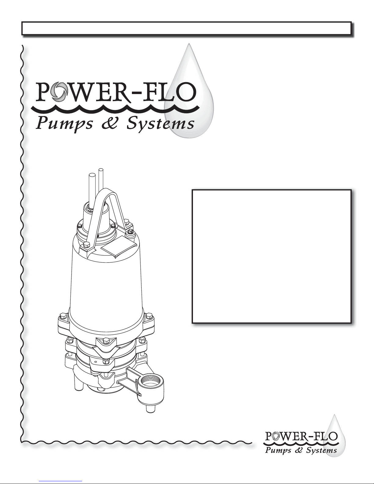
INSTALLATION, SERVICE & PARTS MANUAL
Series: PFG3022, PFG3062,
PFG3032, PFG3042,
PFG5022, PFG5062,
PFG5032, PFG5042,
PFG7532, PFG7542
3, 5 & 7.5HP•3450RPM•60Hz
Submersible Grinder Pump
Power-Flo Pumps & Systems • 877-24PUMPS • www.power opumps.com
ISP No: PFGrinder357 - 5/13
Page 2
PFG 3, 5 & 7.5HP Submersible Grinder Pumps
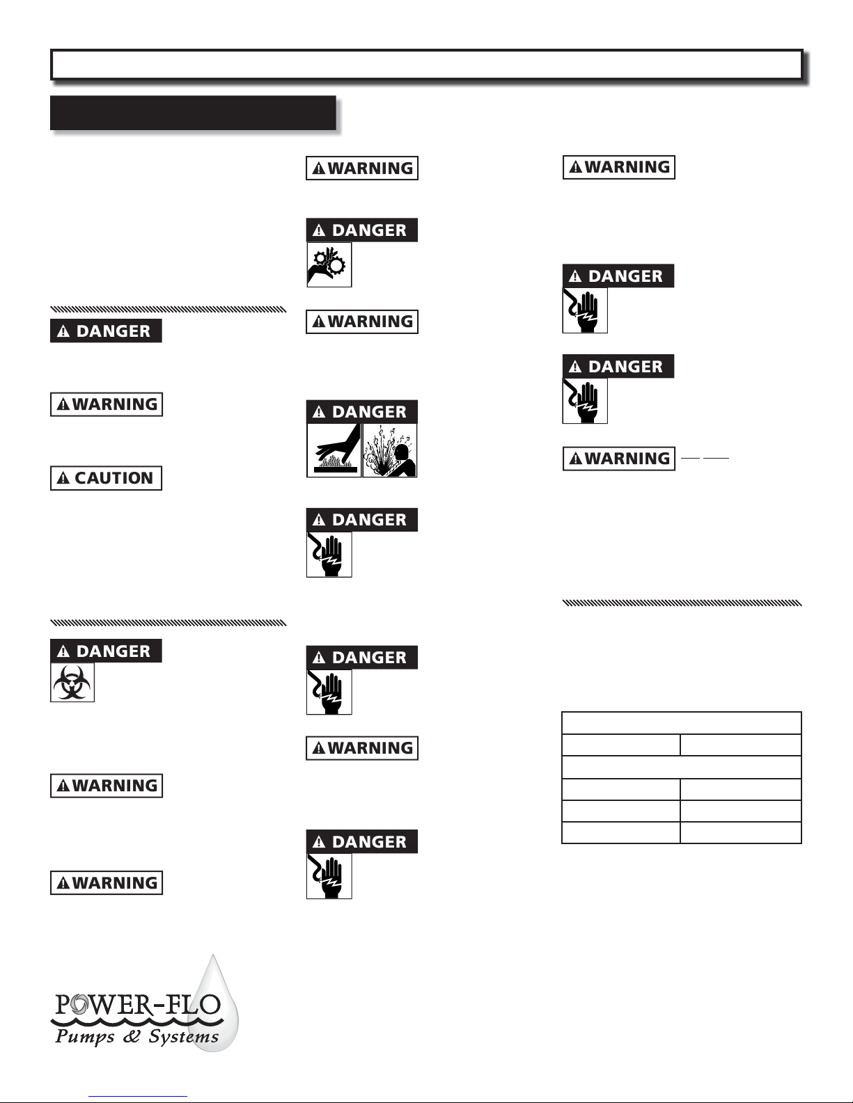
General Safety Information
Before installation, read the following
instructions carefully. Failure to follow
instruction and Safety information could
cause serious bodily injury, death and/or
property damage. Each Power-Flo pump is
individually factory tested to insure proper
performance. Closely following these
instructions will eliminate potential operating
problems, assuring years of trouble-free
service.
“Danger” indicates
an immanent
hazardous situation which, if not avoided,
WILL result in death or serious injury.
“Warning” indicates
an immanent
hazardous situation which, if not avoided,
MAY result in death or serious injury.
“Caution” indicates
an potentially
hazardous situation which, if not avoided,
MAY result in minor or moderate injury.
IMPORTANT - Power-Flo Pumps and
Systems is not responsible for losses, injury
or death resulting from failure to observe
these safety precautions, misuse, abuse or
misapplication of pumps or equipment.
All returned Products
must be Cleaned,
sanitized, Or decontaminated
Prior to shipment, to insure
employees will not be exposed to
health hazards in handling said material.
All applicable laws and regulations shall
apply.
Bronze/brass tted
pumps may contain
levels higher than considered safe for potable
water systems. Government agencies have
determined that leaded copper alloys should
not be used in potable water applications.
Installation, wiring,
and junction
connections must be in accordance with the
National Electric Code and all applicable state
and local codes. Requirements may vary
depending on usage and location.
Installation and
servicing is to be
conducted by quali ed personnel only.
Keep clear of suction
and discharge
openings. Do not insert ngers in
pump with power connected.
Always wear eye
protection when
working on pumps. Do not wear loose
clothing that may become entangled in
moving parts
Pumps build up heat
and pressure during
operation. Allow time
for pumps to cool
before handling or
servicing.
This pump is not
intended for use
in swimming pools or water
installations where human
contact with pumped uid. Pumps
when used as a decorative water fountain
pump MUST be used in circuit protected by
a Ground Fault Interrupter.
Risk of electric shock.
To reduce risk of
electric shock, always disconnect
pump from power source before
handling. Lock out power & tag.
Do not us these
pumps in water
over 104˚F. Do not exceed manufactures
recommended maximum performance, as
this could cause the motor to overheat.
Do not lift, carry or
hang pump by the
electrical cables. Damage to the
electrical cables can cause shock,
burnes or death. Never handle
connected power cords with wet hands. Use
appropriate lifting device.
Sump and sewage
pumps often handle
materials which could cause illness or disease.
wear adequate protective clothing when
working on a used pump or piping. Never
enter a basin after it has been used.
Failure to permanently
ground the pump,
motor and controls before
connecting to power can cause
shock, burns or death.
These pumps are NOT
to be installed in
locations classi ed as hazardous
in accordance with the National
Electric Code, ANSI/NFPA 70.
DO NOT introduced
into any sewer,
either directly, or through a kitchen
waste disposal unit or toilet: Seafood
Shells, Aquarium Gravel, Cat Litter,
Plastic Objects (toys, utensils, etc.),
Sanitary Napkins or Tampons, Diapers,
Rags, Disposable Wipes or Cloth,
Medications, Flammable Material, Oil or
Grease, Strong Chemicals, Gasoline.
IMPORTANT!
Prior to installation, record Model
Number, MFG Date, Amps, Voltage, Phase
and HP, from pump name plate for future
reference. Also record the Voltage and
Current Readings at Startup:
1 Phase Models
Amps: Volts:
3 Phase Models
Amps L1-2: Volts L1-2:
Amps L2-3: Volts L2-3:
Amps L3-1: Volts L3-1:
Model Number: ____________________
MFG Date: ____________
PHASE: ______ HP: _________________
® Power-Flo is a registered trademark of Power-Flo Technologies Inc.
Other brand and product names are trademarks or registered trademarks of their respective holders.
Alteration Rights Reserved. 5/08, 6/09, 9/09, 5/10, 11/10, 1/12, 5/12, 8/12, 11/12, 2/13, 5/13
2
Power-Flo Pumps & Systems • 877-24PUMPS • www.power opumps.com
Page 3
PFG 3, 5 & 7.5HP Submersible Grinder Pumps
Speci cations
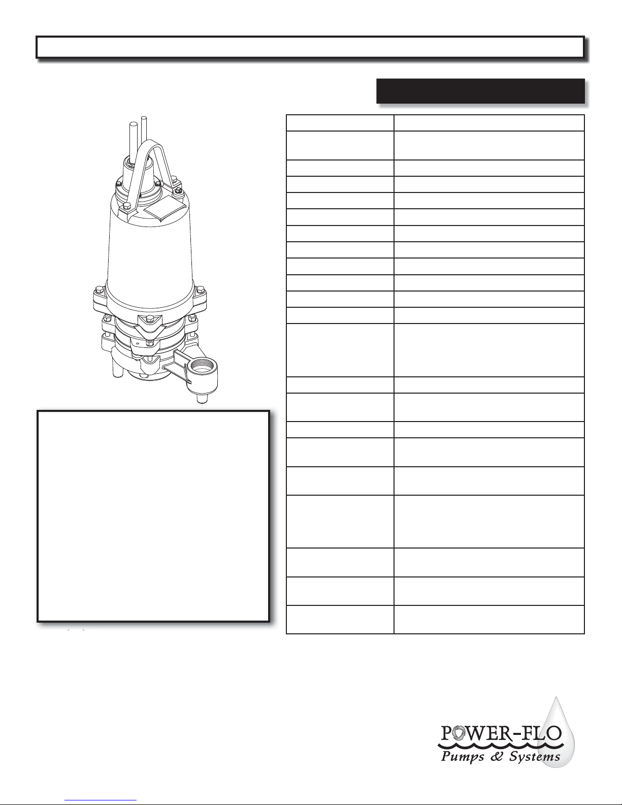
DISCHARGE 2” NPT Vertical, Bolt-on Flange
Series: PFG3022,
PFG3062, PFG3032,
PFG3042, PFG5022,
PFG5062, PFG5032,
PFG5042, PFG7532,
PFG7542
3, 5 & 7.5HP•3450RPM•60Hz
Submersible Grinder Pump
Description
Designed to reduce domestic, commercial, institutional
and light industrial sewage to a nely ground slurry.
LIQUID
TEMPERATURE
VOLUTE Cast Iron, Class 30
MOTOR HOUSING Cast Iron, Class 30
SEAL PLATE Cast Iron, Class 30
IMPELLER Cast Iron, Class 30
SHREDDING RING Stainless Steel
CUTTER Stainless Steel
SHAFT Stainless Steel
SQUARE RINGS Buna-N
HARDWARE Stainless Steel
PAINT Air dry enamel
SEAL
UPPER BEARING Single row, Ball, Oil Lubricated
INTERMEDIATE
BEARING
LOWER BEARING Sleeve, Oil Lubricated
POWER CORD
MOTOR
SINGLE PHASE
THREE PHASE
MOISTURE SENSOR
TEMPERATURE SENSOR
104°F (40°C) Intermittent
Tandem Double Mechanical, Oil Filled
Reservoir, Upper -Carbon/Ceramic/Buna-N,
Lower - Silicon Carbide/Silicon Carbide/Viton
Stainless Hardware
Single row, Ball, Oil Lubricated
30 ft. Cord . Pressure grommet for Sealing
and Strain Relief.
Oil Filled, Squirrel Cage Induction,
Class F Insulation
Capacitor Start/Capacitor Run. Requires
overload protection in the control panel,
Requires starter or control panel which
includes capacitors.
Dual Voltage 230/460. Requires overload
protection in control panel
Normally Open (NO). Requires relay in
control panel
Normally Closed (NC). Requires relay in
control panel
Power-Flo Pumps & Systems • 877-24PUMPS • www.power opumps.com
3
Page 4
PFG 3, 5 & 7.5HP Submersible Grinder Pumps
Speci cations
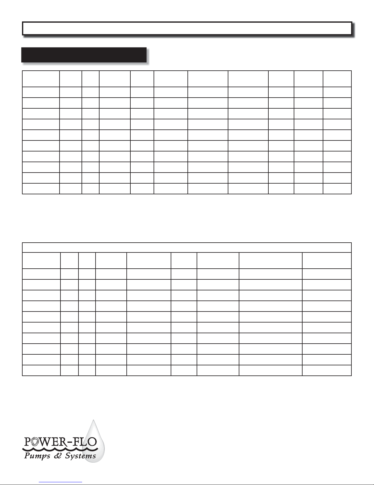
MODEL HP Hz Volts/Ph RPM
PFG3022*
PFG3062 3 60 208/3 3450 17 65 J SOW 10/4 .75
PFG3032 3 60 230/3 3450 14.5 62 K SOW 10/4 .75
PFG3042 3 60 460/3 3450 7.2 31 K SOW 10/4 .75
PFG5022* 5 60 230/1 3450 39 136 H SOW 10/4 .75
PFG5062 5 60 208/3 3450 25 122 K SOW 10/4 .75
PFG5032 5 60 240/3 3450 21.9 120 L SOW 10/4 .75
PFG5042 5 60 460/3 3450 11 60 L SOW 10/4 .75
PFG7532 7.5 60 230/3 3450 22.3 136 J SOW 10/4 .75
PFG7542 7.5 60 460/3 3450 11.2 68 J SOW 10/4 .75
Moisture & Temperature sensor cable for all other models is 18/5 SOW. 0.47 inches O.D. See page 17 for Relay kits.
(*) IMPORTANT! - These pumps require a control panel with start, run capacitors and relay. Capacitor kits which include Start &
Run capacitors and Start Relay, are available if a Power-Flo control panel is not used, see page 17.
3 60 230/1 3450 26 90 H SOW 10/4 .75
Full Load
Amps
Locked
Rotor Amps
NEMA Start
Code
Cord
Typ e
Cord
Size
Cord
O.D.
Recommended Breaker & Heater Sizes
MODEL HP Hz Volts/Ph Breaker Size
PFG3022*
3 60 230/1 80 AMP K-70 MARS 64 189-227 mfd-220 volt 40 mfd - 370 volt
Heater
Size **
Voltage Relay Start Capacitor Run Capacitor
PFG3062 3 60 208/3 40 AMP K-56 N/R N/R N/R
PFG3032 3 60 230/3 30 AMP K-54 N/R N/R N/R
PFG3042 3 60 460/3 15 AMP K-41 N/R N/R N/R
PFG5022* 5 60 230/1 80 AMP K-70 MARS 64 189-227 mfd-220 volt 40 mfd - 370 volt
PFG5062 5 60 208/3 50 AMP K-63 N/R N/R N/R
PFG5032 5 60 240/3 50 AMP K-62 N/R N/R N/R
PFG5042 5 60 480/3 20 AMP K-50 N/R N/R N/R
PFG7532 7.5 60 230/3 50 AMP K-67 N/R N/R N/R
PFG7542 7.5 60 460/3 30 AMP K-54 N/R N/R N/R
N/R = Not Required
Winding resistance ± 5% at terminal block. Rated operation at ± 10% voltage at motor.
(**) Recommended heater sizes may very depending on pump station requirements.
( ) This data is for the PFG3022, from Sept 2010 and newer. For units prior to Sept 2010 use to following: FLA - 21.7, LRA - 75,
NEMA code - G, Breaker Size - 50amp, Heaters K-64, Relay MARS 65, Start Cap. 257mfd - 220volts, Run Cap. 20mfd-370volts.
Power-Flo Pumps & Systems • 877-24PUMPS • www.power opumps.com
4
Page 5
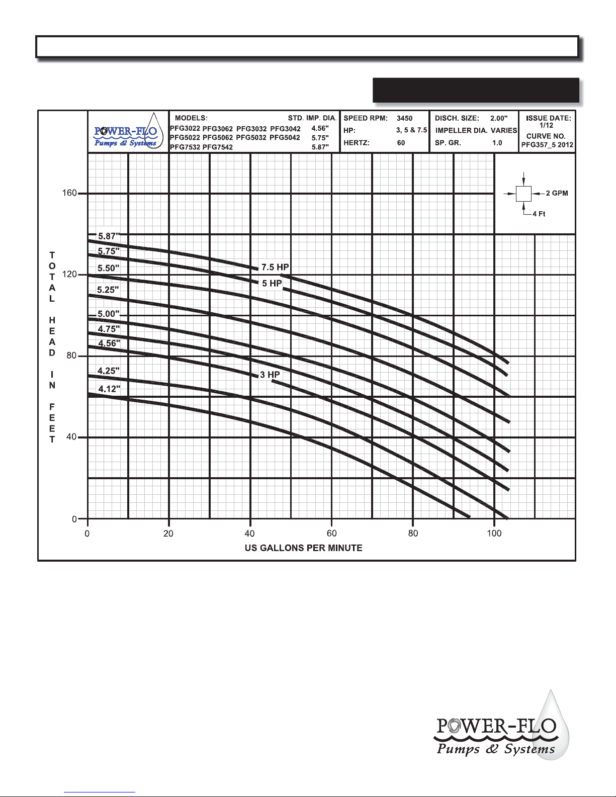
PFG 3, 5 & 7.5HP Submersible Grinder Pumps
Performance
Power-Flo Pumps & Systems • 877-24PUMPS • www.power opumps.com
5
Page 6
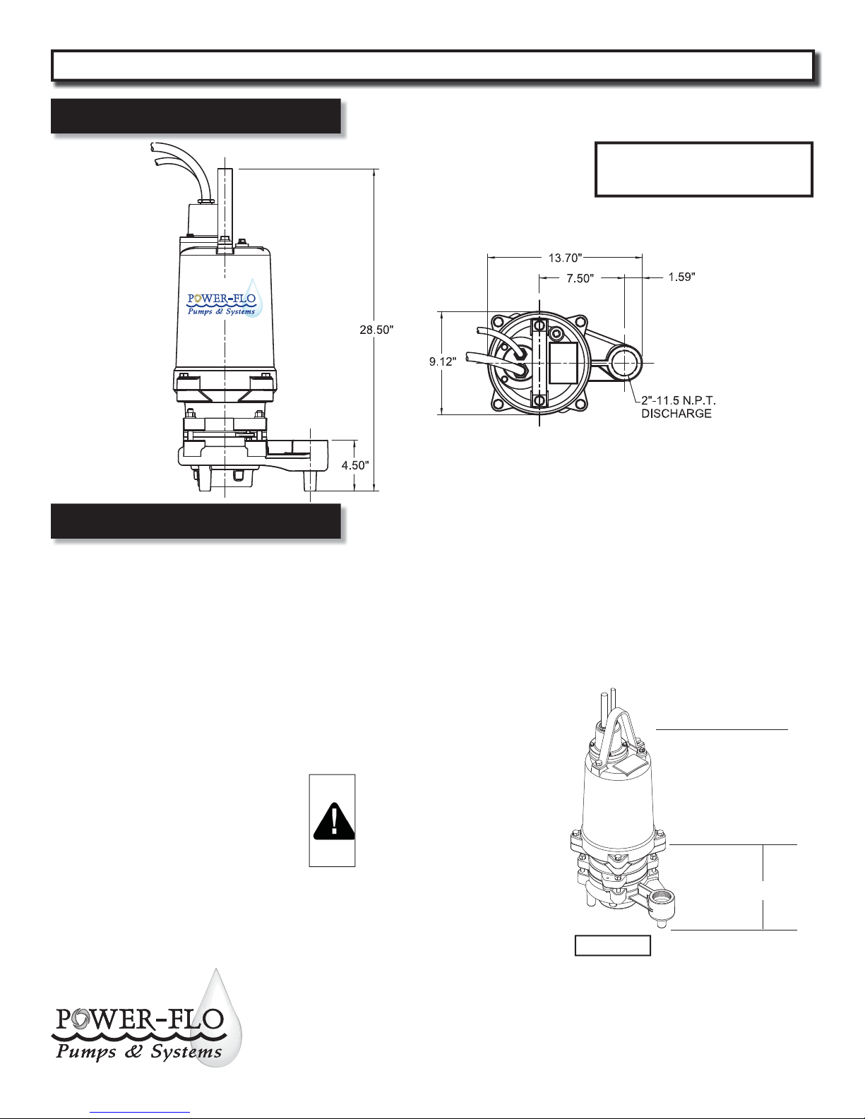
PFG 3, 5 & 7.5HP Submersible Grinder Pumps
Dimensions
IMPORTANT! - Pump Suction MUST be a
minimum of 4” from basin oor with use of
legs, stand or slide rail system.
®
Receiving & Installation
Receiving Inspection
Upon receiving the pump, it should be
inspected for damage or shortages.
If damage has occurred, le a claim
immediately with the company that
delivered the pump. If the manual is
removed from the packaging, do not
lose or misplace.
Storage
Any product that is stored for a period
longer than six (6) months from the
date of purchase should be bench
tested prior to installation. A bench
test consists of, checking the impeller
to assure it is free turning and a run
test to assure the motor (and switch
if provided) operate properly. Do not
pump out of liquid.
Controls
PFG series grinders require a separate
approved pump control device or panel
for automatic operation. Be sure the
electrical speci cation of the control
selected properly match the electrical
speci cations of the pump.
Location
The grinder pump is designed to t in
basin or wetwell by using a slide rail
system.
IMPORTANT ! - A CLEARANCE
UNDER THE PUMP FOR
ENTRANCE OF SEWAGE SOLIDS
MUST BE A MINIMUM OF 3
INCHES TO A MAXIMUM OF 4.5
INCHES.
Submergence
The pump should always be operated in
the submerged condition. The minimum
sump liquid level should never be less
than above the pump’s volute (See Figure
1).
Recommended
Submergence Level
Minimum
Submergence Level
5”
6
Figure 1
Power-Flo Pumps & Systems • 877-24PUMPS • www.power opumps.com
Bottom of Feet
Page 7
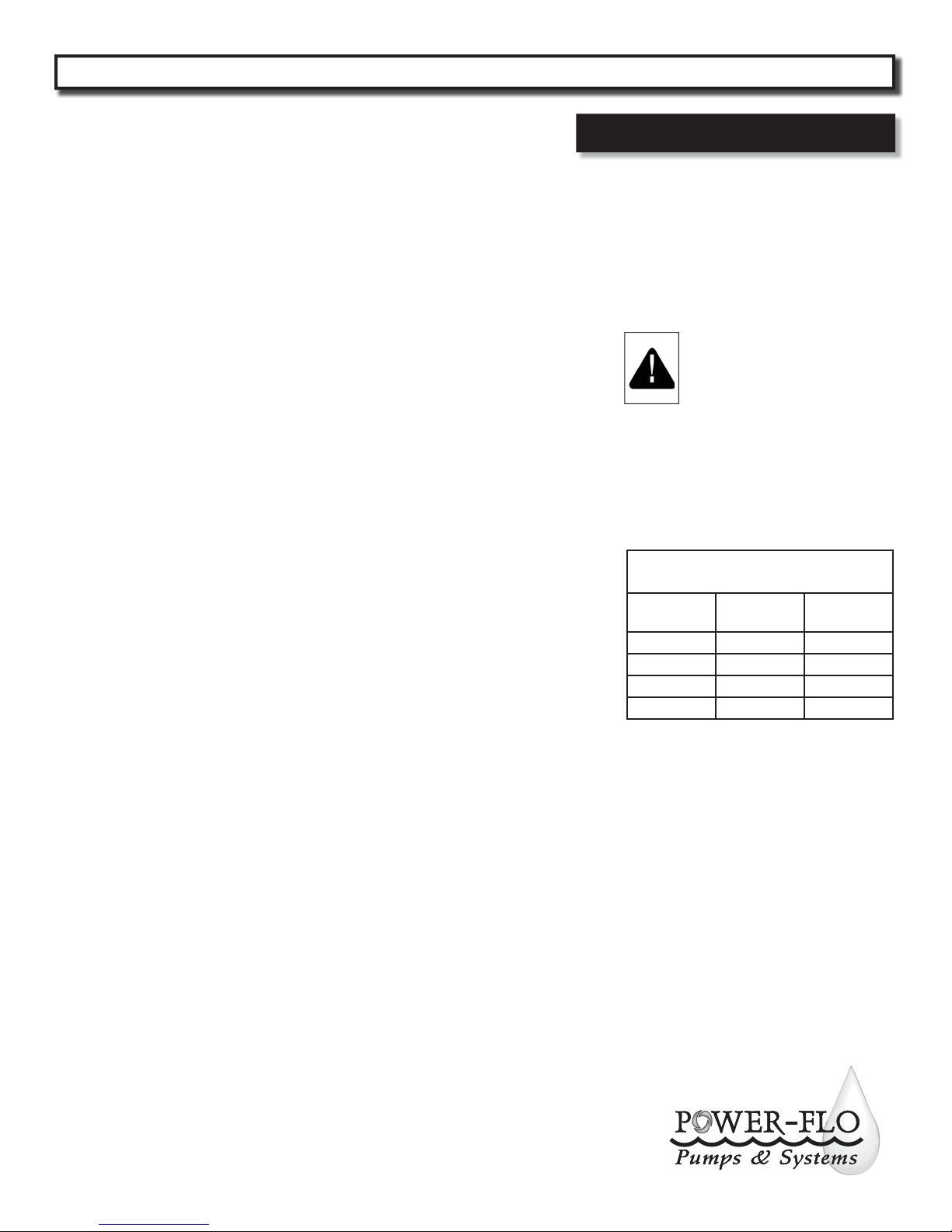
PFG 3, 5 & 7.5HP Submersible Grinder Pumps
Receiving & Installation
Installation
There are several methods of installing
grinder pumps. See contract plans and/
or speci cation: A slide rail in a package
system or concrete wet well is the most
common, which allows the pump(s)
to be installed or removed without
requiring personnel to enter the wet
well.
The sump or basin shall be sealed
and vented in accordance with local
plumbing codes. This pump is designed
to pump grinder or wastewater,
nonexplosive and noncorrosive liquids
and shall NOT be installed in locations
classi ed as hazardous in accordance
with the National Electrical Code (NEC)
ANSI/NFPA 70 or Canadian Electric
Code (CEC). The pump should never be
installed in a trench, ditch, or hole with
a dirt bottom. The legs will sink into
the dirt and the suction will become
plugged.
The installation should be at a su cient
depth to ensure that all plumbing
is below the frost line. If this is not
feasible, remove the check valve and
size the basin to accommodate the
additional back ow volume.
Discharge Piping
Discharge piping should be as short
as possible and sized no smaller than
the pump discharge. Do not reduce
the discharge pipe size below that
which is provided on the pump. Both
a check valve and a shut-o valve are
recommended for each pump. The
check valve is used to prevent backow
into the sump. The shut-o valve is
used to manually stop system ow
during pump servicing.
Liquid Level Controls
The level control(s) should be mounted
on the discharge piping, a cable rack
or oat pole. The level control should
have adequate clearance so it cannot
hang up in it’s swing and that the pump
is completely submerged when the
level control is in the “O ” mode. By
adjusting the cord tether the control
level can be changed. One cycle of
operation should be observed, so that any
potential problems can be corrected.
It is recommended that the level control
oat should be set to insure that the liquid
in the sump never drops below the top of
the motor housing or a minimum level of
10 inches above the basin oor.
Electrical Connections
Power cable - The power cable mounted
to the pump must not be modied in any
way except for shortening to a specic
application. Any splice between the pump
and the control panel must be made in
accordance with the electric codes. It
is recommended that a junction box, if
used, be mounted outside the sump or be
of at a minimum Nema 4 construction if
located within the wet well. DO NOT USE
THE POWER CABLE TO LIFT PUMP.
Always rely upon a Certi ed Electrician for
installation.
Thermal Protection:
The normally closed (N/C) over
temperature sensor is embedded in the
motor windings and will detect excessive
heat in the event an overload condition
occurs. The thermal sensor will trip when
the windings become too hot and will
automatically reset when the pump
motor cools to a safe temperature. It is
recommended that the thermal sensor be
connected in series to an alarm device to
alert that an overtemperature condition
and/or motor starter coil to stop pump.
In the event of an overtemperature,
the source of this condition should be
determined and repaired immediately.
Thermal protection shall not be used as a
motor overload device. A separate motor
overload device must be provided in
accordance with NEC code.
WARNING! - DO NOT LET
THE PUMP CYCLE OR RUN IF
AN OVERLOAD CONDITION
OCCURS !
If current through the temperature sensor
exceeds the values listed, an intermediate
control circuit relay must be used to
reduce the current or the sensor will not
work properly.
TEMPERATURE SENSOR ELECTRICAL
RATINGS
Volts Continuous
Amperes
110-120 3.00 30.0
220-240 1.50 15.0
440-480 0.75 7.5
600 0.60 6.0
Moisture Sensor:
To detec any moisture present a normally
open (N/O) probe is installed in the seal
chamber. The probe should be connected
in series to an alarm device or motor
starter coil to alert the operator that
moisture has been detected. Check the
probe leads for continuity, (∞ resistance
= no moisture). Also check the junction
box and control panel for moisture
content as this may induce a false signal.
IF MOISTURE DETECTION OCCURRES,
MAINTENANCE SHOULD BE DONE TO
IDENTIFY AND REPAIR.
Inrush
Amperes
Power-Flo Pumps & Systems • 877-24PUMPS • www.power opumps.com
7
Page 8
PFG 3, 5 & 7.5HP Submersible Grinder Pumps
Installation & Service
Wire Size:
If longer power cable is required consult
a quali ed electrician for proper wire
size.
Pre-Operation
1. Check Voltage and Phase
Compare the voltage and phase
information stamped on the pump
name plate.
2. Check Pump Rotation - Improper
motor rotation can result in poor
pump performance and can damage
the motor and/or pump. Check
rotation on three phase units by
momentarily applying power and
observe the “kickback”.
Kickback should always be in a
counter-clockwise direction as
viewed from motor end or opposite
to impeller rotation. Incorrect rotation
for Single-Phase pumps is unlikely.
If the rotation is incorrect contact
factory.
3. Name Plate - Record the information
from the pump name plate to
drawing in front of manual for future
reference.
4. Insulation Test - An insulation
(megger) test should be performed
on the motor. Before the pump is put
into service. The resistance values
(ohms) as well as the voltage (volts)
and current (amps) should be
recorded.
5. Pump-Down Test - Be sure pump
has been properly wired, lowered into
the basin, sump or lift station, check
the system by lling with liquid and
allowing the pump to operate through
its pumping cycle. The time needed to
empty the system, or pump-down
time along with the volume of water,
should be recorded.
Maintenance
No lubrication or maintenance is required.
Perform the following checks when pump
is removed from operation or when pump
performance deteriorates:
a). Inspect motor chamber for oil level
and contamination.
b). Inspect impeller and body for
excessive build-up or clogging.
c). Inspect motor and bearings.
d). Inspect seal for wear or leakage.
Servicing
NOTE: Item numbers in ( ) refer to Figures
7 & 8.
Cooling Oil - Anytime the pump is
removed from operation, the cooling oil
in the motor housing should be checked
visually for oil level and contamination.
To check oil, set unit upright. Remove
pipe plug (30) from housing (8). With
a ashlight, visually inspect the oil in
housing (8) to make sure it is clean and
clear, light amber in color and free from
suspended particles. Milky white oil
indicates the presence of water. Oil level
should be just above the motor when
pump is in vertical position.
Oil Testing
• Drain oil into a clean, dry container by
placing pump on it’s side, remove pipe
plug (30), from housing (8).
• Check oil for contamination using an
oil tester with a range to 30 Kilovolts
breakdown.
• If oil is found to be clean and
uncontaminated (measuring above
15 KV. breakdown), rell the housing.
• If oil is found to be dirty or
contaminated (or measures below
15 KV. breakdown), the pump must
be carefully inspected for leaks at the
shaft seal, cable assembly, square ring
and pipe plug, before relling with oil.
Tolocate the leak, perform a pressure
test.
After leak is repaired, dispose of old oil
properly, and rell with new oil.
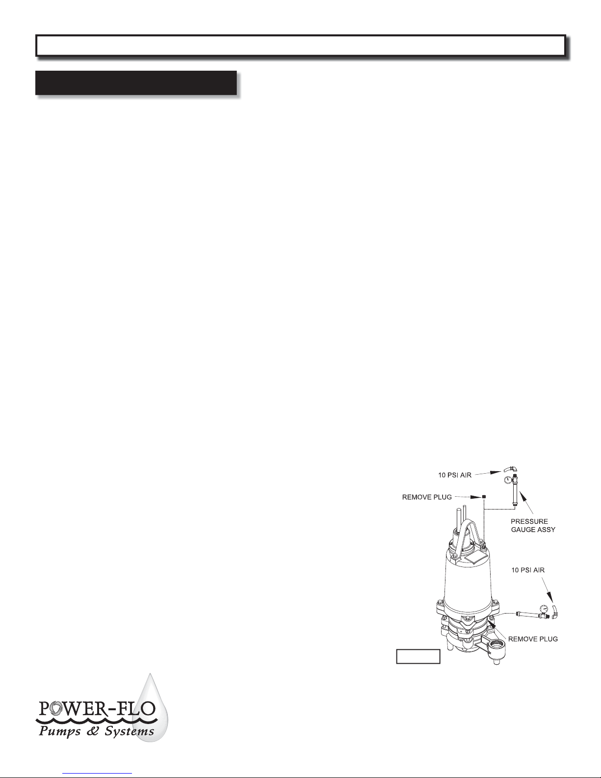
Pressure Test (If oil has been drained)
Remove pipe plug (30) from housing (8).
Apply pipe sealant to pressure gauge
assembly and tighten into hole. Pressurize
motor housing to 10 P.S.I. Use soap
solution around the sealed areas and
inspect joints for “air bubbles”.
If, after ve minutes, the pressure is still
holding constant, and no “bubbles” are
observed, slowly bleed the pressure and
remove the gauge assembly. Replace
oil. Leek must be located and repaired if
pressure does not hold.
Pressure Test (If oil has NOT been
drained) - Oil should be at normal level.
Remove pipe plug (30) from housing (8).
Apply pipe sealant to pressure gauge
assembly and tighten into hole. Pressurize
motor housing to 10 P.S.I. Use soap
solution around the sealed areas above the
oil level and inspect joints for “air bubbles”.
For sealed areas below oil level, leeks will
seep oil. If, after ve minutes, the pressure
is still holding constant, and no “bubbles” /
oil seepage is observed, slowly bleed the
pressure and remove the gauge assembly.
Replace oil. Leek must be located and
repaired if pressure does not hold.
Figure 2
8
Power-Flo Pumps & Systems • 877-24PUMPS • www.power opumps.com
Page 9
PFG 3, 5 & 7.5HP Submersible Grinder Pumps
Service
Pressure builds up extremely
fast, increase pressure by
“TAPPING” air nozzle. Too much
pressure will damage seal. DO
NOT exceed 10 P.S.I.
Seal Chamber - Set pump on its side with
ll plug (30) downward, remove plug (30)
and drain all oil from seal chamber. Apply
pipe sealant to pressure gauge assembly
and tighten into hole in intermediate
coupling (5). Pressurize seal chamber to
10 P.S.I. and check for leaks.
Oil Replacement:
Motor Housing - Drain all oil (if not
already done so) from motor housing
and dispose of properly per Local and
Environmental Standards.
Set pump upright and re ll with new
cooling oil, see “Cooling Oil” chart. Fill to
just above motor as an air space must
remain in the top of the motor housing to
compensate for oil expansion. Apply pipe
thread compound to threads of pipe plug
(30) then assemble to motor housing (8).
Seal Chamber - Drain all oil (if not already
done so) from seal chamber and dispose
of properly per Local and Environmental
Standards. Place pump on its side with
plug (30) upward, and re ll with new oil,
see “Cooling Oil” chart. Apply pipe thread
compond to threads of pipe plug (30) and
assemble to intermediate coupling (5).
DO NOT overll oil. Overlling
of housing with oil can create
excessive and dangerous hydraulic
pressure which can destroy the
pump and create a hazard.
Overlling oil voids warranty.
Cooling Oil
Recommended Supplier/Grade
BP Enerpar SE100
Conoco Pale Parafn 22
Mobile D.T.E. Oil Light
Shell Canada Transformer-10
Texaco Diala-Oil-AX
WARNING ! - Before any service
work is done, disconnect and
lock out electrical power to
pump.
Disassembly
Cutter - Lay pump on its side and remove
the cutter retaining screw (29) and washer
(28). A small amount of heat may be
needed to loosen screw. DO NOT overheat.
Wedge a at screwdriver between cutter
and shredding ring and remove screw.
With a hammer and punch, tap the cutter
(27) counter-clockwise to remove.
CAUTION ! - Cutter edges are
very SHARP. Cutter must be
removed before removing volute.
Volute - Remove hex nuts (25) and
washers (9) from studs (26) and remove
volute (23) and square ring (24) from
pump.
Shredding Ring - To replace or reverse
the shredding ring (20), remove allen
screws (22) and lift throat (21) from volute
(23) then press out using an arbor press.
The shredding ring (20) can be pressed
out and reversed when cutting edges dull.
Impeller - Remove impeller (18) by
turning counter-clockwise while holding
the motor shaft stationary with a
screwdriver. NOTE: Seal spring is relaxed
with impeller removed, some oil may
seep from seal cavity. Do Not store pump
without impeller in place.
Outer Seal - Handle seal parts with care.
Remove seal (34) spring and rotating
member from shaft. Examine all seal
parts. Inspect contact faces for signs of
uneven wear tracks on stationary, chips
and scratches on either seal face. DO NOT
interchange seal components, replace
the entire shaft seal (34).
Seal Plate - Remove cap screws (35) and
washers (38) from seal plate (19). Remove
seal plate (19) and square ring (24) from
intermediate coupling (5). With at
screwdriver, press out seal (34) stationary
member. Inspect square ring (24) for cuts
or abrasions.
Cable Assemblies - Remove Hex plugs
(13B) and (14B), washers (13C) and (14C)
and gromeents (13D) and (14D) from
conduit box (11).
Motor - Remove pipe plug (30) and drain
oil if not already done so. Position pump
upright using blocks or pvc pipe to avoid
resting pump on the shaft. Remove cap
screws (15) and lockwashers (16) from
cable box assembly (11) and slide conduit
box up the cords until motor lead wires
are exposed. Disconnect connectors (17)
from motor leads wires to remove cable
assemblies (13) and (14). Remove ground
screw (31). Remove and inspect o-ring
(12).
Remove cap screws (10) and lockwashers
(9) from motor housing (8). Vertically lift
motor housing (8) from intermediate
coupling (5) along with square ring (7),
replace if cut or damaged. Remove motor
bolts and carefully remove stator housing
from rotor. Remove retaining ring (2) from
intermediate (5) and pull rotor out with
bearing (3) and rotating member of inner
seal.
Power-Flo Pumps & Systems • 877-24PUMPS • www.power opumps.com
9
Page 10
PFG 3, 5 & 7.5HP Submersible Grinder Pumps
Service
Inspect motor winding for shorts and
check resistance values. Check rotor for
wear. If rotor or the stator windings are
defective, the complete motor must be
replaced.
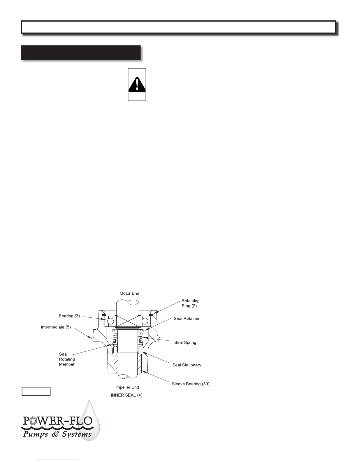
Bearings & Inner Seal - Remove seal (4)
rotating member and spring from rotor
shaft. Press stationary from intermediate
(5) with at screwdriver. Examine all seal
parts. Inspect contact faces for signs of
uneven wear tracks on stationary, chips
and scratches on either seal face. DO
NOT interchange seal components,
replace the entire shaft seal (4).
Remove retaining rings (6) from shaft.
Using a wheel puller or arbor press
remove bearing (3) from shaft. Remove
upper motor bearing from shaft with a
bearing puller. (See Figure 3)
Check sleeve bearing (39) for excessive
wear, if replacement is required the
complete intermediate coupling (5)
should be replaced.
Moisture Probes - Remove screws (37)
and wire (33) from probes (36). Remove
probes (36) from intermediate (5).
IMPORTANT! - All parts must be
clean before reassembly.
Handle seal parts with extreme
care. DO NOT damage lapped
surfaces.
Reassembly
Moisture Probes - Apply thread
compound to thread on probes (36) and
install in intermediate (5). Connect wires
(33) with screws (37).
Bearings - Be careful not to damage
the rotor shaft when replacing bearings.
Using an arbor press, hold the rotor and
press the upper bearing on the rotor
shaft, applying force to the inner race of
the bearing only. Replace upper retaing
ring onto rotor shaft. In the same manner
replace lower bearing (3) onto rotor shaft.
Place lower retaining rings (6) onto shaft.
Inner Seal - Clean and oil seal cavity
in intermediate coupling (5). Lightly
oil (Do not use grease) outer surface
of stationary member. Press seal’s
(4) stationary member rmly into
intermediate coupling (5), using a seal
tool or pipe.
Nothing should come in contact with the
seal face except the seal tool. Be sure the
stationary is in straight. Place seal’s (4)
retaining ring and spring over shaft until
seated on shaft shoulder. Slide a bullet
tool over rotor shaft threads. Lightly oil
(Do not use grease) shaft, bullet, and
inner surface of bellows on rotating
member, with nished end away from
motor, slide rotating member over bullet
and onto shaft until it engages spring.
Make sure spring is seated in retaining
ring and spring is lined up on rotating
member and not cocked or resting on
bellows tail. (See Figure 3)
Motor - Slide rotor/shaft with bearing
(3) and seal parts (4) into intermediate
coupling (5) until bearing seats into
intermediate coupling. Install retaining
ring (2) into intermediate coupling (5).
Place motor stator over rotor, lining up
motor bolts with holes in intermediate
coupling (5). Place end bell on top of
motor and insert motor bolts and torque
to 17 in-lbs.
Wiring Connections - Set square ring
(7) in grove on intermediate coupling
(5). Pull wires through opening in top of
motor housing (8) while lowering motor
housing onto intermediate coupling (5).
Insert capscrews (10) with lockwasher (9)
through motor housing into intermediate
and tighten. Place square ring (12) on
motor housing (8). Place conduit box with
cables next to motor housing and make
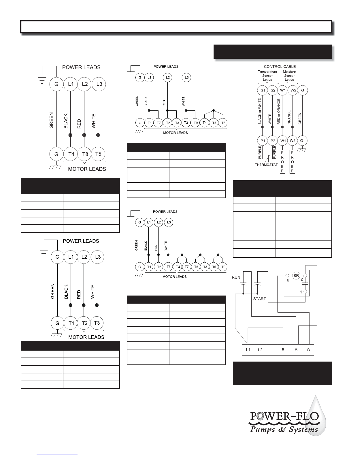
wire connections (see Figure 4). Connect
ground wire (42) with screw (31) to
conduit box (11) if disconnected.
Figure 3
10
Check power cable (13) and control cable
(14) for damage and replace complete
conduit box and cable assembly if
required.
Power-Flo Pumps & Systems • 877-24PUMPS • www.power opumps.com
Page 11
PFG 3, 5 & 7.5HP Submersible Grinder Pumps
Pump Wiring Schematics
FIGURE 4 - THREE PHASE 230 VOLT AC
Power Cable Motor Lead Number
Green (Ground) Green
Black 1 & 7
FIGURE 4 - SINGLE PHASE
230 VOLT AC
Power Cable Motor Lead Number
Green (Ground) Green
Black 4 run
Red 8 start
White 5 common
Red 2 & 8
White 3 & 9
T4, T5 & T6 Together
FIGURE 4
MOISTURE & TEMPERATURE SENSORS
Control Cable Lead Number
Green (Ground) Green
Black or White P1 (Temp Sensor) In
series with starter coil
White P2 (Temp Sensor) In
series with starter coil
Red or Orange W1 (Moisture Sensor)
Orange W2 (Moisture Sensor)
FIGURE 4 - THREE PHASE 208 VOLT AC
Power Cable Motor Lead Number
Green (Ground) Green
Black 1
Red 2
White 3
Power-Flo Pumps & Systems • 877-24PUMPS • www.power opumps.com
FIGURE 4 - THREE PHASE 460 VOLT AC
Power Cable Motor Lead Number
Green (Ground) Green
Black 1
Red 2
White 3
T4 & T7 Together
T5 & T8 Together
T6 & T9 Together
FIGURE 4
1 Phase Capacitor Pack for
Control Panel
11
Page 12
PFG 3, 5 & 7.5HP Submersible Grinder Pumps
Service
Shredding Ring - Install shredding ring
(27) into volute with the use of an arbor
press. Assemble throat (21) into volute
(23) with tree allen screws (22).
Volute - Lubricate square ring (24) and
place in groove in bottom of seal plate
(19). Place volute (23) on seal plate (19)
being careful not to damage square ring
(24). Place nuts (25) with lockwashers (9)
onto studs (26) and torque evenly to 11
ft/lbs.
Figure 5
Place conduit box (11) on motor housing
(8) and insert capscrews (15) with washers
(16) into motor housing and torque to 16
ft/lbs.
Cable Assemblies - Power cable, Place
one friction ring (13C), grommet (13D),
one friction ring (13C) and hex plug (13B)
into conduit box (11). Control Cable, Place
one friction ring (14C), grommet (14D),
one friction ring (14C) and hex plug (14B)
into conduit box (11). Torque hex plugs to
15 ft. lbs. to prevent leakage. See Figures
7 & 8.
Seal Plate - Lubricate and set square
ring (24) in bottom groove of seal plate
(19). Place seal plate (19) over shaft and
onto intermediate coupling (5), being
sure square ring (24) is not twisted and
in the groove. Place two capscrews (35)
with lockwashers (38) into seal plate and
torque to 6.5 ft/lbs.
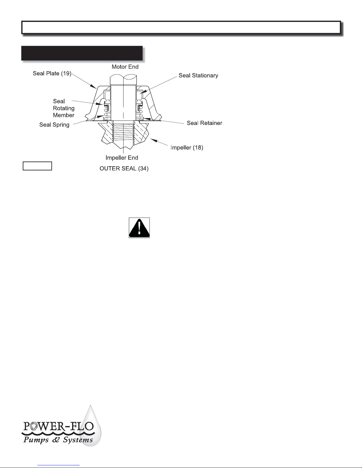
Press stationary rmly into seal plate
(19) using a seal pusher tool. Be sure the
stationary member is in straight. Nothing
but the seal tool is to come in contact
with seal face. (See Figure 5)
IMPORTANT ! Do not hammer
on the seal pusher. It will
damage the seal face.
With seal guide tool over motor shaft,
Lightly oil (Do not use grease) guide,
shaft and inner surface of bellows on
rotating seal.
With lapped surface of rotating member
facing inward toward stationary, slide
rotating member over guide and onto
shaft, using seal pusher tool, until lapped
faces of stationary and rotating seal are
together. Place spring over shaft and
rotating member. Be sure it is seated on
the retainer and not cocked or resting on
bellows tail.
Cutter - Screw radial cutter (27) onto
shaft, turning it clockwise while holding
the shaft stationary with a screwdriver.
The radial cutter (27) should be ush with
shredding ring (20), on suction side to
within ± .020. Place washer (28) on screw
(29), apply green Loctite on threads and
place into shaft and tighten.
Outer Seal - Clean and oil stationary
seal cavity in seal plate (19). Slide seal
guide tool over motor shaft. Lightly oil
(Do not use grease) outer surface of
seal’s (34) stationary member.
12
Impeller - Place impeller (18) on motor
shaft, with machined step tting inside
the inside diameter of seal spring, by
turning clockwise while holding shaft
stationary with screwdriver.
Power-Flo Pumps & Systems • 877-24PUMPS • www.power opumps.com
Page 13
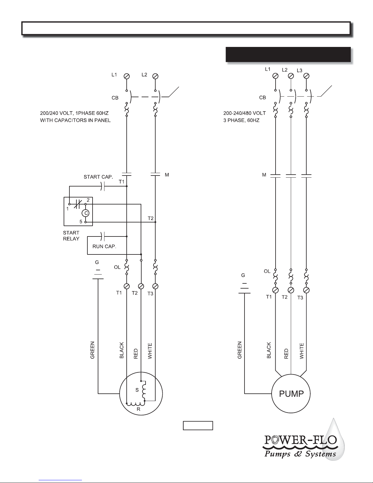
PFG 3, 5 & 7.5HP Submersible Grinder Pumps
Typical Panel Wiring Schematic
Power-Flo Pumps & Systems • 877-24PUMPS • www.power opumps.com
Figure 6
13
Page 14
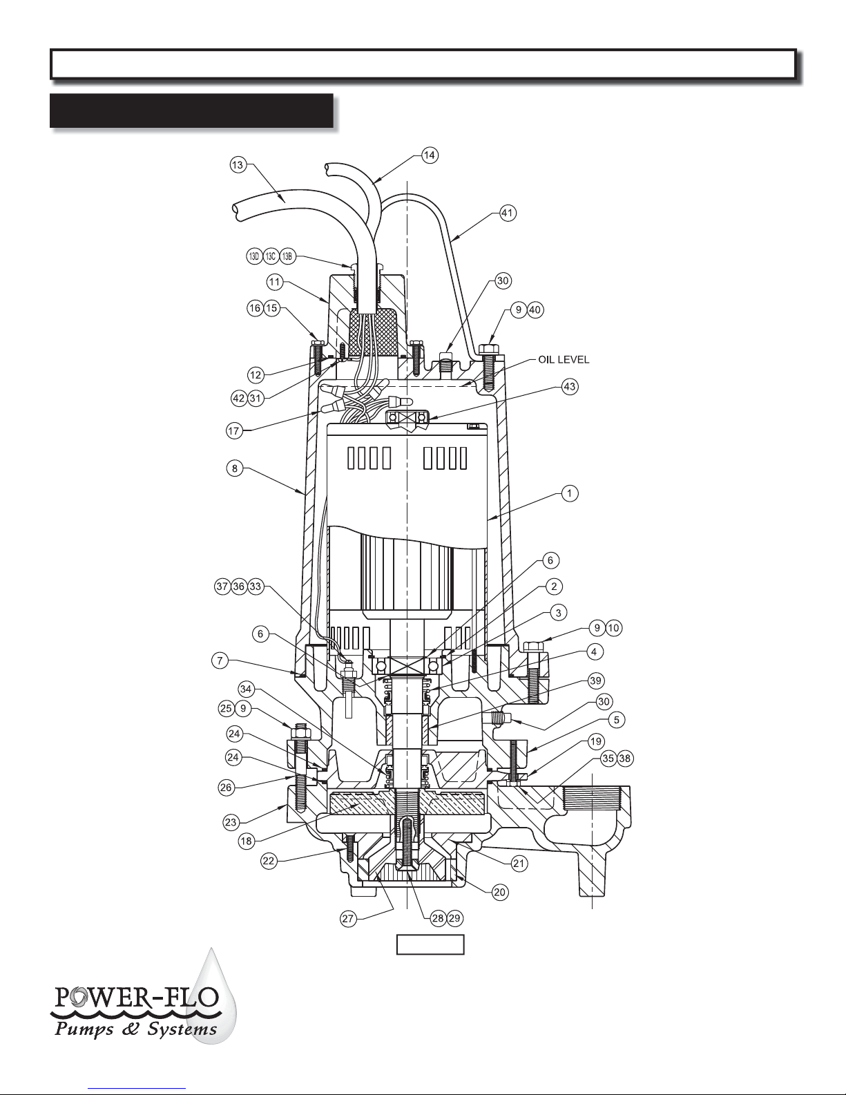
PFG 3, 5 & 7.5HP Submersible Grinder Pumps
Repair Parts
For Repair Part Please supply: Model Number and MFG Date as shown on
Name Plate, and Part Description and Part Number as shown on Parts List.
14
Figure 7
Power-Flo Pumps & Systems • 877-24PUMPS • www.power opumps.com
Page 15
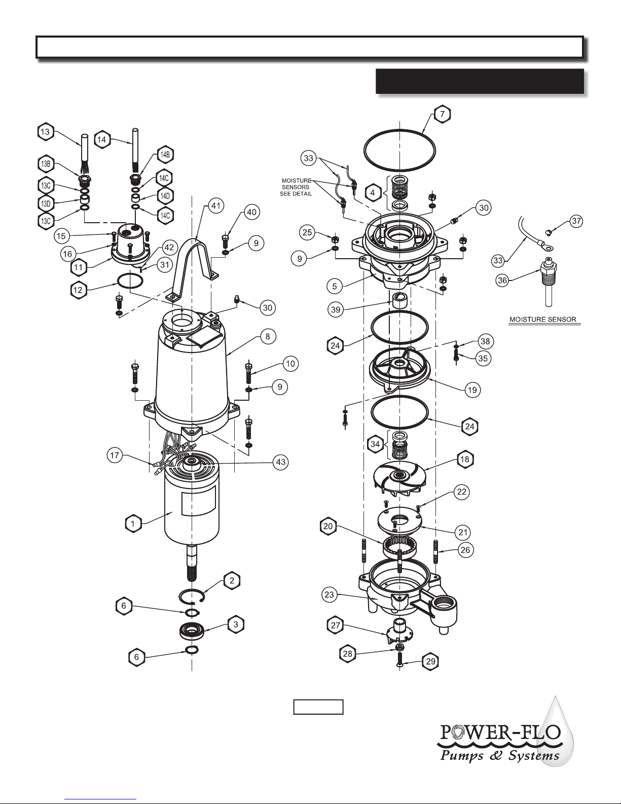
PFG 3, 5 & 7.5HP Submersible Grinder Pumps
For Repair Part Please supply: Model Number and MFG Date as shown on
Name Plate, and Part Description and Part Number as shown on Parts List.
Repair Parts
Power-Flo Pumps & Systems • 877-24PUMPS • www.power opumps.com
Figure 8
15
Page 16
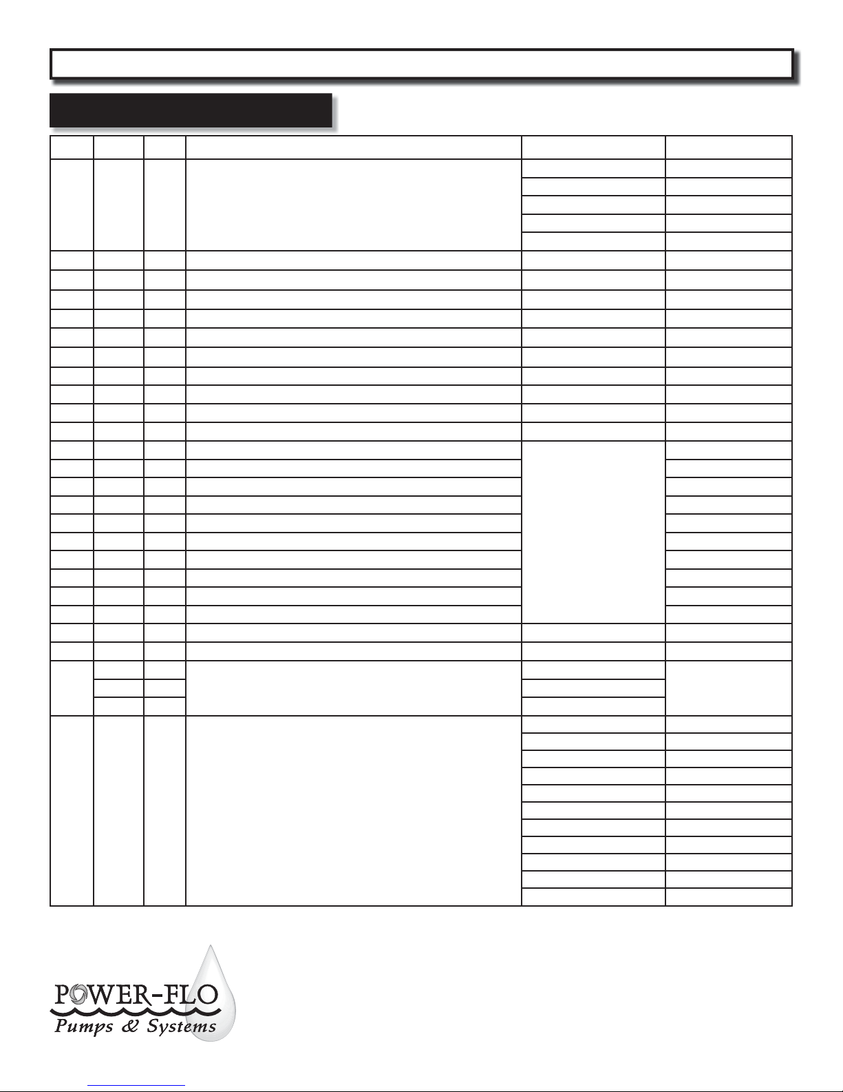
PFG 3, 5 & 7.5HP Submersible Grinder Pumps
Repair Parts
Ref. Qty Name Used On Part Number
Motor
11
22
31
41
5 1 Bearing Housing PF03040026
62
71
8 1 Motor housing PF03100011
9 10 Lockwasher, 7/16 Stainless
10 4 Screw, 7/16-14 x 2.25” Lg., Stainless
11assy
11 1 * Conduit box
12 1 * O-ring PF92010063
13 1 * Power Cable 10/4 SOW PF31030003
13B 1 * Hex Plug PF30400903
13C 2 * Friction ring PF91010055
13D 1 * Grommet PF92010001
14 1 * Moisture & Temperture Sensor Cable, 18/5 SOW, 30Ft. PF31030005
14B 1 * Hex plug PF30400901
14C 2 * Friction ring PF91010057
14D 1 * Grommet PF92010005
15 4 Capscrews, 1/4-20 x 1”Lg., Stainless
16 4 Lockwashers, 1/4” Stainless
17
1
8
11 Three Phase 460V
() Do NOT use PF40040054, Replaced by PF40040055,
size capacitors accordingly, see page 4.
Retaining ring PF31010004
6
Ball bearing, lower, 6207ZZC3 PF31020022
6
Seal, inner C/C/B PF31030136
6
Retaining ring PF31010011
6
Square ring PF92010087
6
Conduit Box & Cable Assembly, 10/4 SOW, 30Ft. PF067585
Wire Connectors
For Repair Part Please supply: Model Number and MFG Date as shown on
Name Plate, and Part Description and Part Number as shown on Parts List.
3 HP 230 Volt 1 Ph PF40040054
3 & 5 HP 230 Volt 1 Ph PF40040055
3 HP 230/460 Volt 3 Ph PF40040051
5 HP 230/460 Volt 3 Ph PF40040052
7.5 HP 230/460 Volt 3 Ph PF40040053
PF03100010
Included
in
Item
#11ASSY
Single Phase 230V
PF940100129 Three Phase 230 V
18 1
16
Impeller
IMPORTANT: Standard impeller sizes prior to June 2011 were as followes;
7.5HP - A; 6.46; 5HP - B; 6.25; 3HP - C; 5.00
= Aquire standard hardware locally.
= Cutter Kit
6 = Overhaul Kit
Power-Flo Pumps & Systems • 877-24PUMPS • www.power opumps.com
5.87” Dia. STD for 7.5HP PF03140079A
5.75” Dia. STD for 5HP PF03140079B
5.50” Dia. ---
5.25” Dia. ---
5.00” Dia. ---
4.75” Dia. ---
4.56” Dia. STD for 3 HP PF03140079C
4.25” Dia. ---
4.12” Dia. ---
= Supplied as individual items
* = Supplied with item #11 Assy
■ = Seal Probe Kit
Page 17
PFG 3, 5 & 7.5HP Submersible Grinder Pumps
For Repair Part Please supply: Model Number and MFG Date as shown on
Name Plate, and Part Description and Part Number as shown on Parts List.
Repair Parts
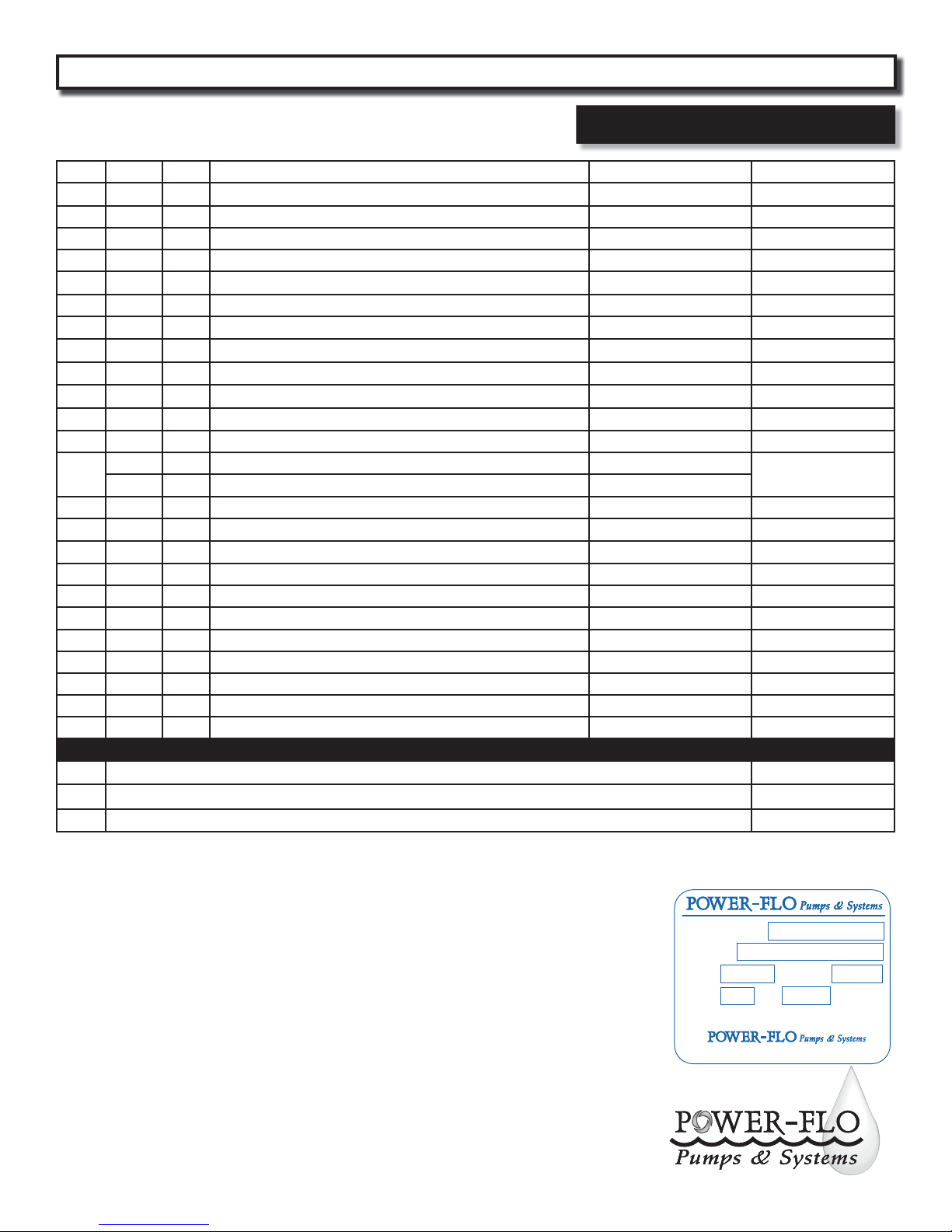
19 1 Seal plate PF03180028
20 1
Shredding ring PF31010020
6
21 1 Throat PF03190021
22 3 Allen Screw, 1/4-20 x .75” Lg, Stainless
23 1 Volute PF03090083
24 2
25 4 Hex nut, 7/16-14 Stainless
26 4 Stud, 7/16-14 x 3.25” Lg., Stainless
27 1
28 1
29 1
30 2 Pipe plug, 1/4” NPT
31 1 * Ground screw, 3/16” x 1/2”
4¾ qts
32
1½ qts
33 2
34 1
35 2 Screw, 5/16-18 x 1.25” Lg. Stainless
36 2
37 2
38 2 Lockwasher, 5/16” Stainless
Square ring PF92010081
6
Radial cutter PF31030301
6
Washer, Stainless PF30400426
6
Screw, 3/8-16 x 1.75” Lg., Stainless PF91010398
6
Cooling oil, Motor housing
Seal cavity
■
Wire Assembly, Moisture Sensor PF31030011
Seal, outer S/S/V PF31030137
6
■
Moisture Sensor Probe PF31160001
■
Machine screw, 6-32 x 1/4” Lg., Stainless Moisture sensors
See chart on page 9
39 1 Bearing sleeve Supplied in item #5
40 2 Screw, 7/16-14 x 1.25” Lg., Stainless
41 1 Lifting bail PF30400843
42 1 * Round terminal, 3/16 PF94010043
43 1 Upper Ball Bearing, 6203ZZ PF070715
Repair Kits
CUTTER KIT - Includes Item numbers: 20, 27, 28, 29
OVERHAUL KIT - Includes Item numbers: 2, 3, 4, 6, 7, 20, 24, 27, 28, 29, 34
6
■
SEAL PROBE KIT - Includes item numbers: 33, 36 & 37 PF69775-1
PFGL-CT
PFGL-OHK
Capacitor Pack for, Other than Power-Flo’s control panel:
For units PRIOR to Sept. 2010 use, P/N: PF73303 - for PFG3022, 230 volt, 1 phase 3 Hp
(See page 11 for wiring schematic).
For units AFTER Sept. 2010 use, P/N: PF73305 - for PFG3022, 3HP & PFG5022 5HP,
230 volt, 1 phase (See page 11 for wiring schematic).
Recommended Moisture & Temperature Sensor Relays for control panel, (or equal):
P/N: PF0861 - Warrick relay #IDIEO rated for 25 volt amperes, 115 volt input,
500 volt output (one per pump).
P/N: PF0876 - IDEC relay #RH2BUAC120V (one per pump).
= Aquire standard hardware locally.
= Cutter Kit
6 = Overhaul Kit
Power-Flo Pumps & Systems • 877-24PUMPS • www.power opumps.com
= Supplied as individual items
* = Supplied with item #11 Assy
■ = Seal Probe Kit
Typical Name Plate
Model Number
MFG Date
AMPS VOLTAGE
PHASE HP
60 Hz
877-24 PUMPS
www.powerflopumps.com
17
Page 18
PFG 3, 5 & 7.5HP Submersible Grinder Pumps
Notes:
18
Power-Flo Pumps & Systems • 877-24PUMPS • www.power opumps.com
Page 19
PFG 3, 5 & 7.5HP Submersible Grinder Pumps
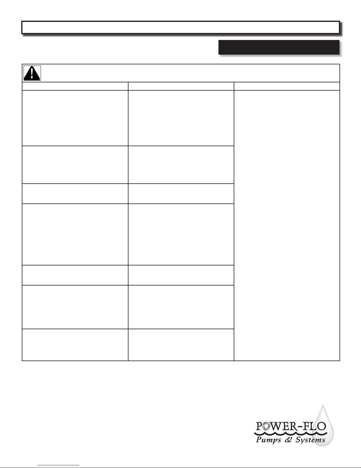
Trouble Shooting Chart
Risk of electric shock. Always disconnect the pump from the power source before handling inspections or repairs.
Symptom Possible Cause(s) Corrective Action
1. Poor electrical connection, blown fuse, tripped
breaker or other interruption of power;
improper power supply
2. Motor or switch inoperative (go to manual
Pump will not run
Pump will not turn o
Pump hums but doesn’t run
Pump delivers insu cient capacity
Pump cycles too frequently or runs periodically
when xtures are not in use
Pump shuts o and turns on independent of
switch, (trips thermal overload protector).
CAUTION! Pump may start unexpectedly.
Disconnect power supply.
Pump operates noisily or vibrates excessively
NOTE: Power-Flo Pumps & Systems assumes no responsibility for damage or injury due to disassembly in the eld. Disassembly of the pumps or supplied
accessories other than at Power-Flo Pumps & Systems or its authorized service centers, automatically voids warranty.
operation)
2a. Float movement restricted
2b. Switch will not activate pump or is defective
2c. Defective motor
3. Insu cient liquid level
2a. Float movement restricted
2b. Switch will not activate pump or is defective
4. Ecessive in ow or pump not properly sized for
application
9. Pump may be air locked causing pump not to ow
14. H-O-A switch on panel is in “HAND” position
1. Incorrect low voltage
8. Impeller jammed or loose on shaft, or inlet
plugged
1. Incorrect low voltage
4. Ecessive in ow or pump not properly sized for
application
5. Discharge restricted
6. Check valve partially closed or installed backwards
7. Shut-o valve closed
8. Impeller jammed or loose on shaft, or inlet
plugged
9. Pump may be air locked causing pump not to ow
10. Pump running backwards
6. Check valve partially closed or installed backwards
11. Fixtures are leaking
15. Ground water entering basin
1. Incorrect low voltage
4. Ecessive in ow or pump not properly sized for
application
8. Impeller jammed or loose on shaft, or inlet
plugged
12. Excessive water temperature (internal
protection only)
2c. Worn bearings, motor shaft bent
5. Debris in impeller cavity or broken impeller
10. Pumprunning backwards
13. Piping attachments to building structure too
loose or rigid
1. Check all electrical connections for security.
Have electrician measure current in motor leads,
if current is within ± 20% of locked rotor Amps,
impeller is probably locked. If current is 0,
overload may be tripped. Remove power, allow
pump to cool, then re-check current.
2a. Reposition pump or clean basin as required to
provide adaquate clearance for oat
2b. Disconnect level control. Set ohmmeter for a
low rang, such as 100 ohms full scale and
connect to level control leads. Actuate level
control manually and check to see that
ohmmeter shows zero ohms for closed switch
and full scale for open switch. (Float Switch)
2c. Check winding insulation (Megger Test) and
winding resistance. If check is outside of range,
dry and re-check. If still defective, replace per
service instructions.
3. Make sure liquid level is above the pump
4. Re-check all sizing calculations to determine
proper pump size.
5. Check discharge line for restrictions, including
ice if line passes through or into cold areas.
6. Remove and examine check valve for proper
installation and freedom of operation
7. Open valve
8. Check impeller for freedom of operation,
security and condition. Clean impeller cavity
and inlet of any obstruction
9. Loosen union slightly to allow trapped air to
escape. Verify that turn-o level of switch is set
so that the suction is always ooded. Clean vent
hole
10. Check rotation. If power supply is three phase,
reverse any two of three power supply leads to
ensure proper impeller rotation
11. Repair xtures as required to eliminate leakage
12. Check pump temperature limits and uid
temperature
13. Replace portion of discharge pipe with exible
connector or tighten existing piping.
14. Turn to automatic position
15. Check for leaks around basin inlet and outlets
Power-Flo Pumps & Systems • 877-24PUMPS • www.power opumps.com
19
Page 20

PFG 3, 5 & 7.5HP Submersible Grinder Pumps
LIMITED WARRANTY
Manufacturer warrants, to the immediate purchaser and subsequent initial owner during the warranty period,
every new pump to be free from defects in material and workmanship under normal use and service, when properly
used and maintained, for a period of eighteen (18) months from date of manufacture or twelve (12) months from
date of installation (which ever comes rst). Failure due to wear due to excessive abrasives is not covered. The
initial owner is the purchaser who rst uses the pump after its initial installation, or for non-permanent installation,
the rst owner who uses the pump. The date of installation shall be determined by a dated sales receipt noting the
model and serial number of the pump. The dated sales receipt must accompany the returned pump. Product will be
repaired, replaced or remanufactured at Manufacturer’s option. No allowance will be made for shipping charges,
damages, labor or other charges that may occur due to product failure, repair or replacement. This warranty does
not apply to and there shall be no warranty for any material or product that has been disassembled without prior
approval of Manufacturer, subjected to misuse, misapplication, neglect, alteration, accident or act of God; that has
not been installed, operated or maintained in accordance with Manufacturer’s installation instructions; that has
been exposed to outside substances including but not limited to the following: sand, gravel, cement, mud, tar,
hydrocarbons, hydrocarbon derivatives (oil, gasoline, solvents, etc.), or other abrasive or corrosive substances, wash
towels or feminine sanitary products, etc. in all pumping applications. The warranty set out in the paragraph above
is in lieu of all other warranties expressed or implied; and we do not authorize any representative or other person
to assume for us any other liability in connection with our products. Contact Manufacturer at: 1-877-24PUMPS or
www.power opumps.com, Attention: Customer Service Department, to obtain any needed repair or replacement
of part(s) or additional information pertaining to our warranty.
MANUFACTURER EXPRESSLY DISCLAIMS LIABILITY FOR SPECIAL, CONSEQUENTIAL OR INCIDENTAL
DAMAGES OR BREACH OF EXPRESSED OR IMPLIED WARRANTY; AND ANY IMPLIED WARRANTY OF FITNESS
FOR A PARTICULAR PURPOSE AND OF MERCHANTABILITY SHALL BE LIMITED TO THE DURATION OF THE
EXPRESSED WARRANTY.
Some states do not allow limitations on the duration of an implied warranty, so the above limitation may not apply
to you. Some states do not allow the exclusion or limitation of incidental or consequential damages, so the above
limitation or exclusion may not apply to you. This warranty gives you speci c legal rights and you may also have
other rights which vary from state to state.
Power-Flo Pumps & Systems • 877-24PUMPS • www.power opumps.com
20
 Loading...