

Page 1

TABLE OF CONTENTS
SECTION PAGE
1 GENERAL INFORMATION 2
2 SAFETY GUIDELINES 3
3 COMPONENTS & CONTROLS 4
3.1 How The Pressure Washer Works 4
3.2 Controls 5
4 ASSEMBLY INSTRUCTIONS 7
4.1 Assembly for Item 8102477 7
4.2 Assembly for Item 8038317 8
4.3 Assembly for Item 8186322 8
4.4 Assembly for Item 8038382 8
4.5 Assembly for Item 8186306 9
4.6 Assembly for Item 8093254 10
4.7 Assembly for Item 8093247 11
4.8 Assembly for Item 8093270 12
4.9 Assembly for Item 8093262 13
4.10 Assembly for Item 8186751 14
4.11 Hose Reel Installation 15
5 OPERATION 16
5.1 Water Connections 16
5.2 Before Starting Your Pressure Washer 16
5.3 Prime The Pump 17
5.4 Starting/Stopping The Pressure Washer 17
5.5 Washing 18
5.6 Chemical Additives 19
5.7 Determining Chemical Additive-to-Water Ratio 19
5.8 Storage 20
5.9 Washing Tips 20
6 MAINTENANCE 21
6.1 Maintenance Safety 21
6.2 Preventative Maintenance 21
6.2.1 Anti-Freezing The Pressure Washer (Winterizing) 21
6.2.2 Routine Inspection 22
6.2.3 Pulley Alignment & Belt Tension (for items 8093262
& 8186751)
7 TROUBLESHOOTING 24
8 SPECIFICATIONS 25
9 ASSEMBLY PART LISTS 28
22
1
Page 2

1. GENERAL INFORMATION
Congratulations on your choice of a Power Fist Pressure Washer. This equipment has be en designed and
manufactured to meet the needs of a discerning light industrial and consumer customer for efficient washing
and cleaning.
Power Fist Pressure Washers are categorized based on their applications into the followi ng three classes:
Consumer Class: pressure washers are designed for up to 3 hours a week of use, for such applications as
washing your car, sidewalk, lawnmower or your home.
Commercial/Agricultural Class: pressure washers are designed for up to 20 hours a week of use, and are
most commonly used for vehicle washing, storefront cleaning, and plant maintenance.
Contractor/Industrial Class: pressure washers have a usage rating of 20 hours or more pe r week, for such
applications as contract cleaning, paint preparation and washing trucks or heavy equipm ent.
Safe, efficient and trouble free operation of your Washer requires that you and anyone else who will be
operating or maintaining the machine, read and understand all of the safety, operation, maintenance and
troubleshooting information contained within this Operator’s Manual.
WARRANTY- PARTS - SERVICE
If you experience any problems and need assistance or parts and repair service please contact Princess A uto
Ltd. at:
Telephone # 1-800-665-8685 Fax # 1-800-265-4212
To obtain prompt, efficient service, always provide the serial number and item number of your unit. See the
parts list for location of the serial number decal. Please mark the numbers in the space provided for easy
reference.
SERIAL # ________________________
ITEM # ________________________
Printed in Canada 10002738-1
Issue Date: October 2008 Revision 10
2
Page 3
2. SAFETY GUIDELINES
DEFINITIONS
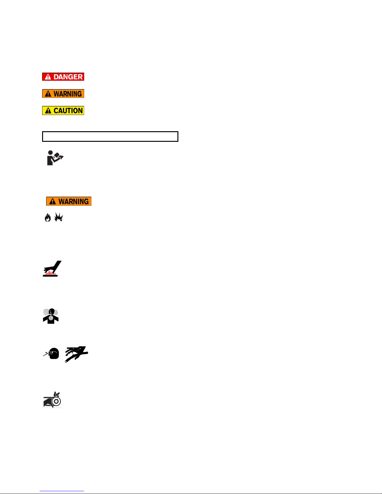
Safety symbols identify important safety messages that alert to the possibility of personal injury or death.
Review them carefully before operating the unit and before performing maintenance or repairs. Check the rules
and regulations at your location and identify possible hazards. The appropriate signal word for each message
has been selected using the following guidelines:
- Danger indicates an immediate and specific hazard, which will result in severe personal
injury or death if the proper precautions are not taken.
- Warning indicates a specific hazard or unsafe practice, which could result in severe
personal injury or death if proper precautions are not taken.
- Caution indicates a potentially hazardous situation, which may result in minor or moderate
injury if proper practices are not taken.
____________________________________________________________________________
IMPORTANT SAFETY INSTRUCTIONS
Read and understand the operator’s manual and all safety alerts before operating or maintaining your
pressure washer. Be certain that everyone operating this equipment is familiar with the recommended
operating and maintenance procedures and follows all the safety precautions. Never let children or untrained
adults operate the machine.
_______________________________________________________________________________
RISK OF FIRE OR EXPLOSION
Spilled gasoline and its vapors can ignite from cigarette sparks, electrical arcing, exhaust gases, and hot
engine components such as the muffler. Never refuel the engine while it is hot or running. Move unit away from
refueling area before starting engine. Operate and fuel equipment in well-ventilated areas free from
obstructions.
RISK OF BURNS
High temperatures are generated by the operation of the pressure washer. Contact with hot surfaces, such as
the engine exhaust components could result in a serious burn. Allow them to cool off before handling or
servicing. Keep children away from the pressure washer at all times.
RISK TO BREATHING
Do not operate equipment in an enclosed area. Engine exhaust contains carbon monoxide, an odorless,
colorless, deadly poison.
HIGH PRESSURE FLUIDS
Wear proper hand and eye protection when searching for a high-pressure leak. Do not place hand or fingers
in front of the nozzle or point spray at yourself or others. In the event that high-pressure spray penetrates the
skin, seek medical attention immediately.
RISK OF INJURY
Do not operate with belt guard removed. Wait for all moving parts to stop before taking belt guard off for
servicing. Belt guard must be fastened in place before starting the pressure washer.
3
Page 4
3. COMPONENTS & CONTROLS
A
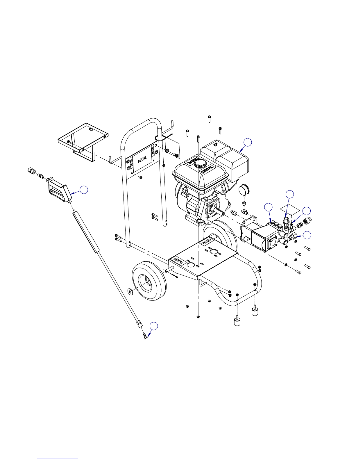
3.1 HOW THE PRESSURE WASHER WORKS
The gas engine powers the plunger piston pump to pressurize the incoming water supplied by a standard
garden hose. The pressurized water flows through an operator controlled u nloader valve to set the system
pressure. The unloader valve also allows the gas engine and pump to run under a no-load condition wh en the
spray gun trigger is released. The pressurized water then goes past the injecting valve to add a liquid
chemical should it be desired. A spray gun wand is used to direct the fluid to the desired spot.
Engine E Injector Valve
B Pump F Spray Gun
C Hose Intake G Nozzle
D Unloader Valve
A
F
B
G
D
E
C
Figure 1: Pressure Washer Components
4
Page 5
3.2 CONTROLS
1. Engine Controls – See Engine Manual
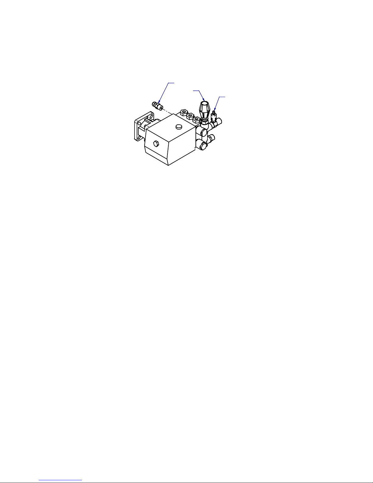
2. Unloader Valve
Controls the system pressure. The unloader is pre-set at the factory to a maximum system pressure.
Do not readjust this maximum pressure setting. If a lower working pressure is required, turn unloader
knob counter-clockwise.
THERMALRELIEF
UNLOADER
CHEMICAL
INJECTOR
VALVE
3. Pressure Gauge
For items 8038382, 8186306, 8093254, 8093247, 8093270, 809326 2 and 8186751. Used to measure
the system pressure. Pressure gauges are available at our Princess Auto stores if required for other
models.
4. Injector Valve
This valve allows the operator to add soap, detergent or chemical to the water only in the low-pressure
mode, i.e. less than 500 PSI (3400 kPa). Turn knob clockwise into the body to lower the flow of
detergent. Back it out by turning the knob counter-clockwise to increase the flow of detergent. Do not
turn more than one and a half turns. Note: not all injector valves are adjustable.
5. Thermal Relief
Provides high temperature protection for pump to prevent premature failure of seals, packings and
cups without interruption of flow.
6. Spray Gun
The hand held spray wand is located at the end of the high-pressure line.
a) Hand Grip
Provides a convenient and comfortable place for the operator to grasp and hold the spray wand.
b) Trigger
Controls the wand valve that allows water to flow though nozzles. Pull trigger toward the hand grip
to start the flow.
c) Safety Latch
Locks the trigger in its OFF position. Flip the latch up into its stowed position when washing.
Always use safety latch when the wand is laid down for any reason.
d) Lance
Extension pipe (available in different lengths with insulation at the Princess Auto store).
e) Quick-Change Nozzle Fitting
Allows easy changing of nozzle sizes.
Figure 2: Unloader Valve, Chemical Injector and Thermal Relief
5
Page 6
3.2 CONTROLS (cont’d)
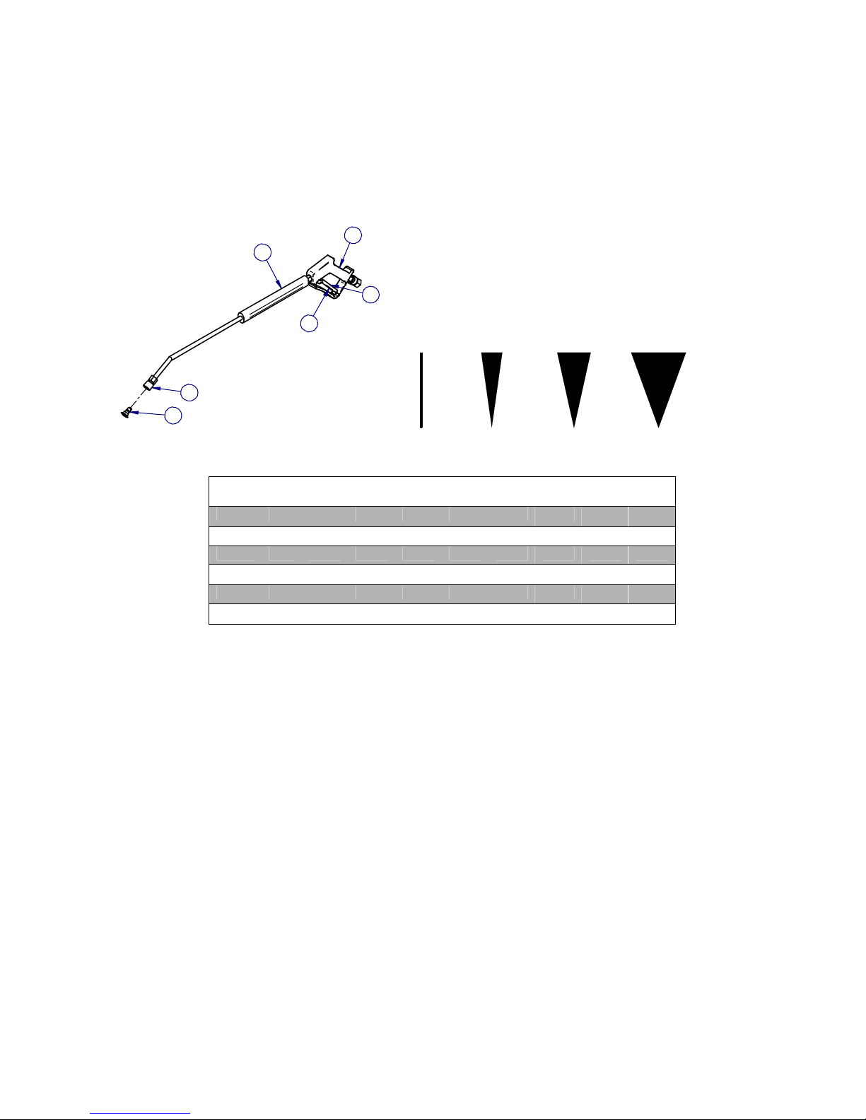
f) Nozzle
To select the correct nozzle size, determine the pressure (PSI) and flow (GPM) rating of your
pressure washer. This can be found on the manufacturer’s serial plate or literature.
Using the chart for nozzle requirements (see Figure 3 below) read across the top to the PSI of
your pressure washer then read down the column to the GPM of your pressure washer. The
correct orifice size is the number in the far left column. Most manufacturers will imprint an
identification code that will tell you the spray angle and the orifice size. For example, “25040”
means the nozzle has a spray angle of 25° and has a 4.0 size orifice.
D
A
C
B
E
F
APPROXIMATE GALLONS PER MINUTE (GPM)
Orifice
Size
3.0 1.4 1.5 1.6 1.8 2.1 2.4 2.6 2.7 2.8
4.0 1.8 2.0 2.2 2.5 2.8 3.1 3.5 3.8 4.0
4.5 2.0 2.2 2.4 2.8 3.0 3.6 3.9 4.3 4.5
5.0 2.2 2.5 2.8 3.1 3.6 4.0 4.4 4.7 5.0
6.0 2.7 3.0 3.3 3.7 4.2 4.7 5.2 5.6 6.0
7.0 3.1 3.5 3.9 4.3 4.6 5.5 6.1 6.5 7.0
800
PSI
1000
PSI
Nozzle
Spray
0° 15° 25° 40°
1200
PSI
1500
PSI
2000
PSI
2500
PSI
3000
PSI
3500
PSI
4000
PSI
Figure 3: Spray Gun Components and Nozzle Chart
6
Page 7

4. ASSEMBLY INSTRUCTIONS
The washer is shipped in a carton and requires assembly before it can be used. Follow this procedure when
assembling:
1. Select an area that is firm and dry with sufficient space to work around all sides of the unit.
2. Remove all components from the carton.
3. Refer to your model assembly below. See the referenced pages for exploded assembly views.
NOTE: Use pipe sealant or Teflon tape on all threaded connections to eliminate leaks.
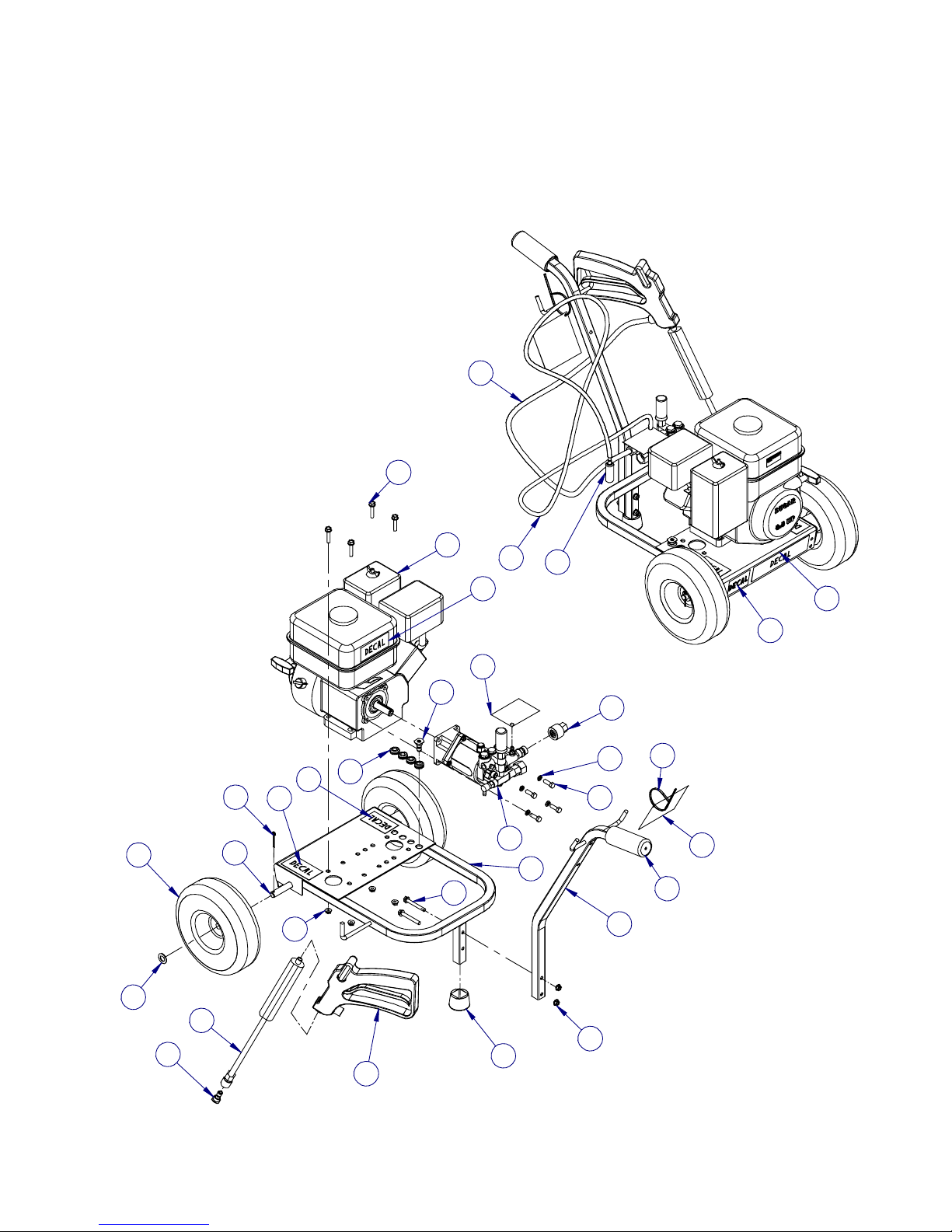
4.1 ASSEMBLY FOR ITEM 8102477 (ref. pages 28-29)
1. Install wheels (10) and axle (5) to base (1) using cotter pins (12) and washers (11).
2. Install rubber plug (9) on base (1).
3. Install handle (4) using bolts (13) and nuts (14).
4. Install engine (2) on base (1) using bolts (21) and nuts (14).
5. Assemble coupler (24) on hose (29).
6. Assemble spray gun (7) on free end of the hose (29).
7. Assemble wand (8) to spray gun (7).
8. Assemble hose/coupler (29/24) to the discharge end of the pump (3).
9. Install quick-change nozzle (26) to wand (8).
10. If you are using detergent:
a) Install clear hose (30 ) to chemical injector on pump (3).
b) Install strainer (18) at free end of clear hose (30).
c) Insert strainer end into detergent container (not included).
11. Check that all parts are installed properly and are securely tightened.
4.2 ASSEMBLY FOR ITEM 8038317 (ref. pages 30-31)
1. Install wheels (11) and axle (8) to frame (1) using cotter pins (13) and washers (15).
2. Install rubber tip (7) on base (1).
3. Install engine (2) on base (1) using bolts (9) and nuts (10).
4. Install handle frame (5) on base frame (1) using bolts (9) and nuts (10).
5. Install chemical tank holder (6) on frame handle (5) using bolts (12) and nuts (10).
6. Assemble male quick coupler (23) to the spray gun (20).
7. Assemble wand (21) to spray gun (20).
8. Assemble female quick disconnect coupler (24) on hose (34).
7
Page 8

4.2 ASSEMBLY FOR ITEM 8038317 (ref. pages 30-31)
9. Assemble coupler (28) on free end of hose (34).
10. Assemble hose/coupler (34/28) to the discharge end of the pump (3).
11. Connect spray gun (20) to hose (34).
12. Install rubber grommets (14) and nozzle (22) to handle (5).
13. If you are using detergent:
a) Install clear hose (33 ) to chemical injector on pump (3).
b) Install strainer (16) at free end of clear hose (33).
c) Insert strainer end (16) into detergent container (not included).
Check that all parts are installed properly and are securely tightened.
4.3 ASSEMBLY FOR ITEM 8186322 (ref. pages 32-33)
1. Install wheels (9) and axle (6) to frame (1) using cotter pins (11) and washers (13).
2. Install rubber tip (5) on base (1).
3. Install engine (2) on base (1) using bolts (7) and nuts (8).
4. Install handle frame (3) on base frame (1) using bolts (7) and nuts (8).
5. Install chemical tank holder (4) on frame handle (3) using bolts (10) and nuts (8).
6. Assemble male quick coupler (20) to the spray gun (17).
7. Assemble wand (18) to spray gun (17).
8. Assemble female quick disconnect coupler (21) on hose (31).
9. Assemble coupler (25) on free end of hose (31).
10. Assemble hose/coupler (31/25) to the discharge end of the pump (36).
11. Connect spray gun (17) to hose (31).
12. Install rubber grommets (12) and nozzle (19) to handle (3).
13. If you are using detergent:
a) Install clear hose (30 ) to chemical injector on pump (36).
b) Install strainer (14) at free end of clear hose (30).
c) Insert strainer end (14) into detergent container (not included).
Check that all parts are installed properly and are securely tightened.
4.4 ASSEMBLY FOR ITEM 8038382 (ref. pages 34-35)
1. Install handle (17) to base (1) using bolts (22) and nuts (26).
2. Install wheels (35), washers (34) and axle (33) to base (1) using cotter pins (37).
3. Install rubber feet (32) using nuts (26).
4. Install rubber grommets (16) to handle (17).
8
Page 9

4.4 ASSEMBLY FOR ITEM 8038382 (ref. pages 34-35)
5. Install engine (11) on base (1) using bolts (22) and nuts (26).
6. Assemble male quick coupler (29) to the spray gun (30).
7. Assemble wand (31) to spray gun (30).
8. Assemble female quick disconnect coupler (28) on hose (14).
9. Assemble coupler (6) on free end of hose (14).
10. Assemble hose/coupler (14/6) to the coupler at the discharge end of the pump (3).
11. Assemble detergent holder (25) to handle (17) using bolts (20) and nuts (26).
14. If you are using detergent:
a) Install clear hose (13 ) to chemical injector on pump (3).
b) Install strainer (24) at free end of clear hose (13).
c) Insert strainer end into detergent container (not included).
15. Check that all parts are installed properly and are securely tightened.
4.5 ASSEMBLY FOR ITEM 8186306 (ref. pages 36-37)
1. Install handle (11) to base (1) using bolts (16) and nuts (20).
2. Install wheels (29), washers (28) and axle (27) to base (1) using cotter pins (31).
3. Install rubber feet (26) using nuts (20).
4. Install rubber grommets (10) to handle (11).
5. Install engine (6) on base (1) using bolts (16) and nuts (20).
6. Assemble male quick coupler (23) to the spray gun (24).
7. Assemble wand (25) to spray gun (24).
8. Assemble female quick disconnect coupler (22) on hose (8).
9. Assemble coupler (5) on free end of hose (8).
10. Assemble hose/coupler (8/5) to the discharge end of the pump (37).
11. Assemble detergent holder (19) to handle (11) using bolts (14) and nuts (20).
12. If you are using detergent:
a) Install clear hose (7) to che m ical injector on pump (37).
b) Install strainer (18) at free end of clear hose (7).
c) Insert strainer end into detergent container (not included).
13. Check that all parts are installed properly and are securely tightened.
9
Page 10

4.6 ASSEMBLY FOR ITEM 8093254 (ref. pages 38-39)
1. Install rubber feet (7) to rear leg (6) using nuts (8).
2. Install rear leg (6) to base (1) using bolts (9) and nuts (8).
3. Place axle (15) through holes on base (1). Place spacers (17) on axle on either side of the base.
Place wheels (4) on the axle so the spacers are snug against the flanges of the base. Center the axle
so an equal amount of threads are exposed from the hub of each wheel.
4. Install washers (32) and lock nuts (36) on the threaded ends of axle. Note that the axle has right hand
threads on both ends. Using a 1-1/16 wrench on each end, as one nut is tightened the opposit e will
tighten. Tighten the nuts enough so the washers are flush with the bearing/hub (i.e. do not rattle), but
avoid over-tightening as the washer will press against the bearing and prevent the wheel from turning.
The lock nuts will be close to their proper installed position once the ends of the axle threads become
flush with the top face of the lock nuts.
If it is necessary to remove the wheels, loosen one nut - holding the opposite nut with a wrench. Once
the nut is off, use a pair of vice-grips to lock the axle (place grips somewhere along the middle of the
axle underneath the base, and avoid gouging the metal) and then remove the opposite nut. An
alternative is to remove the axle from the base once the nut is off and use a vice to take off the
remaining wheel.
5. Install front frame (5) to base (1) using bolts (12), washers (11) and nuts (24).
6. Install jug holder (10) to base (1) using bolts (9) and nuts (8).
7. Install rear handle assembly (3) to base (1) using bolts (12), washers (11) and nuts (24).
8. Install rubber grommets (14) to rear handle assembly (3).
9. Install quick-change nozzles (18, 19, 20) to rubber grommets (14).
10. Install pump/engine assembly to base (1) using bolts (16) and nuts (8).
11. Install male quick coupler (25) to the spray gun (13).
12. Install lance (23) to spray gun (13).
13. Install quick-change nozzle (27) to lance (23).
14. Install female quick-coupler (26) to hose (47).
15. Connect hose (47) to spray gun (13).
16. Install coupler (48) to free-end of hose (47).
17. Connect hose/coupler (47/48) to the discharge end of the pump (28) using coupler (50).
18. If you are using detergent:
a) Attach clear hose (46) to chemical injector on pump (28).
b) Install strainer (45) at free end of clear hose (46).
c) Insert strainer end into detergent container (not supplied).
10
Page 11

4.7 ASSEMBLY FOR ITEM 8093247 (ref. pages 40-41)
1. Install rubber feet (6) to rear leg (5) using nuts (8).
2. Install rear leg (5) to base (1) using bolts (7) and nuts (8).
3. Place axle (13) through holes on base (1). Place spacers (14) on axle on either side of the base.
Place wheels (39) on the axle so the spacers are snug against the flanges of the base. Center the
axle so an equal amount of threads are exposed from the hub of each wheel.
4. Install washers (27) and lock nuts (26) on the threaded ends of the axle. Note that the axle has right
hand threads on both ends. Using a 1-1/16 wrench on each end, as one nut is tightened the opposite
will tighten. Tighten the nuts enough so the washers are flush with the bearing/hub (i.e. do not rattle),
but avoid over-tightening as the washer will press against the bearing and prevent the wheel from
turning. The lock nuts will be close to their proper installed position once the ends of the axle become
flush with the top face of the lock nuts.
If it is necessary to remove the wheels, loosen one nut - holding the opposite nut with a wrench. Once
the nut is off, use a pair of vice-grips to lock the axle (place grips somewhere along the middle of the
axle underneath the base, and avoid gouging the metal) and then remove the opposite nut. An
alternative is to remove the axle from the base once the nut is off and use a vice to take off the
remaining wheel.
5. Install front frame (4) to base (1) using bolts (10), washers (9) and nuts (23).
6. Install jug holder (12) to base (1) using bolts (7) and nuts (8).
7. Install rear handle assembly (3) to base (1) using bolts (10), washers (9) and nuts (23).
8. Install rubber grommets (16) to rear handle assembly (3).
9. Install quick-change nozzles (17, 18, 40) to rubber grommets (16).
10. Install pump/engine assembly to base (1) using bolts (15), washers (46) and nuts (8).
11. Install male quick coupler (24) to the spray gun (11).
12. Install lance (21) to spray gun (11).
13. Install quick-change nozzle (22) to lance (21).
14. Install female quick-coupler (25) to hose (41).
15. Connect hose (41) to spray gun (11).
16. Install coupler (42) to free-end of hose (41).
17. Connect hose/coupler (41/42) to the discharge end of the pump (45).
18. If you are using detergent:
a) Attach clear hose (37) to chemical injector on pump (45).
b) Install strainer (38) at free end of clear hose (37).
c) Insert strainer end into detergent container (not supplied).
11
Page 12

4.8 ASSEMBLY FOR ITEM 8093270 (ref. pages 42-43)
1. Install rubber feet (6) to rear leg (5) using nuts (7).
2. Install rear leg (5) to base (1) using bolts (8) and nuts (7).
3. Place axle (13) through holes on base (1). Place spacers (14) on axle on either side of the base.
Place wheels (45) on the axle so the spacers are snug against the flanges of the base. Center the
axle so an equal amount of threads are exposed from the hub of each wheel.
4. Install washers (39) and lock nuts (40) on the threaded ends of the axle. Note that the axle has right
hand threads on both ends. Using a 1-1/16 wrench on each end, as one nut is tightened the opposite
will tighten. Tighten the nuts enough so the washers are flush with the bearing/hub (i.e. do not rattle),
but avoid over-tightening as the washer will press against the bearing and prevent the wheel from
turning. The lock nuts will be close to their proper installed position once the ends of the axle threads
become flush with the top face of the lock nuts.
If it is necessary to remove the wheels, loosen one nut - holding the opposite nut with a wrench. Once
the nut is off, use a pair of vice-grips to lock the axle (place grips somewhere along the middle of the
axle underneath the base, and avoid gouging the metal) and then remove the opposite nut. An
alternative is to remove the axle from the base once the nut is off and use a vice to take off the
remaining wheel.
5. Install front frame (4) to base (1) using bolts (10), washers (9) and nuts (24).
6. Install jug holder (12) to base (1) using bolts (8) and nuts (7).
7. Install rear handle assembly (3) to base (1) using bolts (10), washers (9) and nuts (24).
8. Install rubber grommets (16) to rear handle assembly (3).
9. Install quick-change nozzles (17, 18, 19) to rubber grommets (16).
10. Install pump/engine assembly to base (1) using bolts (15) and nuts (7).
11. Install male quick coupler (25) to the spray gun (11).
12. Install lance (22) to spray gun (11).
13. Install quick-change nozzle (23) to lance (22).
14. Install female quick-coupler (26) to hose (27).
15. Connect hose (27) to spray gun (11).
16. Install coupler (43) to free-end of hose (27).
17. Connect hose/coupler (27/43) to the discharge end of the pump (47).
18. If you are using detergent:
a) Attach clear hose (41) to chemical injector on pump (47).
b) Install strainer (42) at free end of clear hose (41).
c) Insert strainer end into detergent container (not supplied).
12
Page 13

4.9 ASSEMBLY FOR ITEM 8093262 (ref. pages 44-45)
1. Remove the wooden carton supports that are fastened to the base of the pressure washer subassembly by removing the screws (2 per support).
2. Install rubber feet (6) to rear leg (5) using nuts (7).
Prior to steps 4 through 6, place the base (1) consisting of the pump/engine on a stool or bench for
ease of assembly. CAUTION, the sub-assembly is very heavy.
3. Install rear leg (5) to base (1) using bolts (8) and nuts (7).
4. Place axle (18) through holes on base (1). Place spacers (17) on axle on either side of the base.
Place wheels (54) on the axle so the spacers are snug against the flanges of the base. Center the
axle so an equal amount of threads are exposed from the hub of each wheel.
5. Install washers (46) and lock nuts (45) on the threaded ends of axle. Note that the axle has right hand
threads on both ends. Using a 1-1/16 wrench on each end, as one nut is tightened the opposit e will
tighten. Tighten the nuts enough so the washers are flush with the bearing/hub (i.e. do not rattle), but
avoid over-tightening as the washer will press against the bearing and prevent the wheel from turning.
The lock nuts will be close to their proper installed position once the ends of the axle threads become
flush with the top face of the lock nuts.
If it is necessary to remove the wheels, loosen one nut - holding the opposite nut with a wrench. Once
the nut is off, use a pair of vice-grips to lock the axle (place grips somewhere along the middle of the
axle underneath the base, and avoid gouging the metal) and then remove the opposite nut. An
alternative is to remove the axle from the base once the nut is off and use a vice to take off the
remaining wheel.
6. Install front frame (4) to base (1) using bolts (10), washers (9) and nuts (30).
7. Install rear handle assembly (3) to base (1) using bolts (10), washers (9) and nuts (30).
8. Install jug holder (19) to belt guard (15) using bolts (8) and nuts (7).
9. Install belt guard (15) to base (1) using bolts (8) and nuts (7).
10. Install rubber grommets (20) to rear handle assembly (3).
11. Install quick-change nozzles (21, 23, 24) to rubber grommets (20).
12. Install male quick coupler (28) to the spray gun (11).
13. Install lance (26) to spray gun (11).
14. Install quick-change nozzle (27) to lance (26).
15. Install female quick-coupler (29) to hose (61).
16. Connect hose (61) to spray gun (11).
17. Install coupler (56) to free-end of hose (61).
18. Connect hose/coupler (61/56) to the coupler (38) at the discharge end of the pump (35).
19. If you are using detergent:
a) Attach clear hose (60) to chemical injector on pump (35).
b) Install strainer (53) at free end of clear hose (60).
c) Insert strainer end into detergent container (not supplied).
13
Page 14

4.10 ASSEMBLY FOR ITEM 8186751 (ref. pages 46-47)
1. Remove the wooden carton supports that are fastened to the base of the pressure washer subassembly by removing the screws (2 per support).
2. Install rubber feet (6) to rear leg (5) using nuts (7).
Prior to steps 4 through 6, place the base (1) consisting of the pump/engine on a stool or bench for
ease of assembly. CAUTION, the sub-assembly is very heavy.
3. Install rear leg (5) to base (1) using bolts (8) and nuts (7).
4. Place axle (18) through holes on base (1). Place spacers (17) on axle on either side of the base.
Place wheels (49) on the axle so the spacers are snug against the flanges of the base. Center the
axle so an equal amount of threads are exposed from the hub of each wheel.
5. Install washers (43) and lock nuts (42) on the threaded ends of axle. Note that the axle has right hand
threads on both ends. Using a 1-1/16 wrench on each end, as one nut is tightened the opposit e will
tighten. Tighten the nuts enough so the washers are flush with the bearing/hub (i.e. do not rattle), but
avoid over-tightening as the washer will press against the bearing and prevent the wheel from turning.
The lock nuts will be close to their proper installed position once the ends of the axle threads become
flush with the top face of the lock nuts.
If it is necessary to remove the wheels, loosen one nut - holding the opposite nut with a wrench. Once
the nut is off, use a pair of vice-grips to lock the axle (place grips somewhere along the middle of the
axle underneath the base, and avoid gouging the metal) and then remove the opposite nut. An
alternative is to remove the axle from the base once the nut is off and use a vice to take off the
remaining wheel.
6. Install front frame (4) to base (1) using bolts (10), washers (9) and nuts (30).
7. Install rear handle assembly (3) to base (1) using bolts (10), washers (9) and nuts (30).
8. Install jug holder (19) to belt guard (15) using bolts (8) and nuts (7).
9. Install belt guard (15) to base (1) using bolts (8) and nuts (7).
10. Install rubber grommets (20) to rear handle assembly (3).
11. Install quick-change nozzles (21, 23, 24) to rubber grommets (20).
12. Install male quick coupler (28) to the spray gun (11).
13. Install lance (26) to spray gun (11).
14. Install quick-change nozzle (27) to lance (26).
15. Install female quick-coupler (29) to hose (55).
16. Connect hose (55) to spray gun (11).
17. Install coupler (51) to free-end of hose (55).
18. Connect hose/coupler (55/51) to the discharge end of the pump (33).
19. If you are using detergent:
a) Attach clear hose (54) to chemical injector on pump (33).
b) Install strainer (48) at free end of clear hose (54).
c) Insert strainer end into detergent container (not supplied).
14
Page 15

4.11 HOSE REEL INSTALLATION
Items 8093247, 8093254, 8093270, 8093262 and 8186751 provide the option of installing a hose reel on the
top of the rear handle assembly (see Figure 4 below).
Please note that a hose reel is not included with these pressure washers. The 4000 PSI hose reel can be
purchased at any Princess Auto store under item number 8055908.
Figure 4: Hose Reel Installation
15
Page 16

5. OPERATION
5.1 WATER CONNECTIONS
Water is supplied to the pump from an external source, normally a garden hose. To safely and efficiently use
the pressure washer follow this procedure:
1. Connect the water hose (not supplied) to the inlet swivel ring at the water tap. IMPORTANT! The
hose should not be longer than 25 feet to avoid pressure-drop related problems.
2. The water supply should be pressurized (not exceeding 125 PSI). IMPORTANT! If the water is used
from an open source, use extra screens and a filter to remove all grit and contaminants.
3. A water supply must meet the following specifications:
a) For proper pe rformance, THE SUPPLY WATER FLOW MUST BE 1.5 TO 2 TIMES WHAT THE
PUMP REQUIRES.
Example: if the unit is rated at 3 gallons-per-minute (GPM), then the supply water flow should be
4.5 to 6 GPM.
b) Do not allow the inlet water temperatu re to exceed 65°C (149°C). Water that exceeds this
temperature can damage the pump seals causing crankcase oil to mix with water flow.
5.2 BEFORE STARTING YOUR PRESSURE WASHER
Follow this list before using the washer and each time thereafter to maintain the unit in good condition:
1. Be sure you understand all safety precautions outlined in Section 2 and from the labels/decals applied
to the pressure washer.
2. REPLACE THE SHIPPING OIL CAP WITH THE OIL BREATHER CAP
included with the pump in a small plastic bag. THE OIL BREATHER CAP MUST BE INSTALLED
IMMEDIATELY BEFORE USE.
3. CHECK THE PUMP OIL LEVEL:
• Pump oil level must be at the center of the sight glass. Do not over fill or under fill as it could
damage the pump.
• Replace oil after the first 50 hours of use. Replace oil every 500 hours of operation thereafter.
• Only use non-dete rgent, SAE 20-30 weight oil designed for pressure washer pumps.
4. CHECK THE ENGINE OIL LEVEL. THE ENGINES DO NOT COME WITH OIL! Use the markings on
the oil dipstick to determine the required amount. Do not overfill. Consult the engine owner’s manual
for details.
5. Ensure the pressure washer is sitting level on firm ground.
6. Check for loose hardware. Tighten if necessary.
7. Check for water leaks at fittings. Tighten loose fittings or apply Teflon tape. Replace any damaged or
worn components.
8. Ensure that the plastic screen is in the water inlet swivel ring with the tip pointing up.
. The oil breather cap is
16
Page 17

5.3 PRIME THE PUMP
When using the pressure washer for the first time or after a long storag e period, follow this procedure to
ensure that the pump primes:
1. Prepare unit and worksite. Turn on the supply water.
2. Hold the trigger for at least one minute until the spray leaves the nozzle in a steady stream (no
sputtering).
3. Start the engine.
4. Always use this technique after the pressure washer is brought out of storage. The pump may lose its
prime during storage and this allows it to prime quickly.
5.4 STARTING/STOPPING THE PRESSURE WASHER
To start or stop the pressure washer, follow this procedure:
1. Starting
a) Review Section 5.2.
b) Make sure that water is available to the pump by turning on water from the garden hose line.
c) CHECK THE OIL LEVELS IN THE PUMP AND ENGINE (see Section 5.2).
d) Ensure the pump is p rimed (see Section 5.3).
e) Install the spark pl ug wire if it was removed.
f) To start the engine, refer to the engine owner’s manual.
2. Stopping
a) If it is necessary to stop washing, release the spray gun trigger and flip the safety latch into
position under the trigger.
b) Lay the spray gun down.
c) IMPORTANT! The pump goes into bypass when the gun trigger is relea sed and the motor is still
running. Exit bypass by pressing the gun trigger to spray water. DO NOT LET THE PUMP
REMAIN IN BYPASS FOR LONGER THAN 1-2 MINUTES. Prolonged bypass will damage the
pump.
d) For complete shutdown:
i. Move the throttle control lever to the idle position to reduce engine speed (RPM).
ii. Turn the engine switch to the OFF position.
iii. Turn off the outside water supply.
iv. Continue to depress the spray gun trigger until the water stops flowing to relieve the internal
pressure.
v. Remove the spark plug wire to prevent accidental start up.
vi. Refer to Section 6.2.1 if the unit will see f reezing temperatures during its shutdown or storage
period.
17
Page 18

5.5 WASHING
1. Review Section 5.2.
2. Organize the work to be done. Unwrap as much of the pressure hose that will be required. Position
the washer out of the way of the spray.
3. Turn on water supply.
4. Be sure the safety latch is in position under the trigger.
5. Clear the area of bystanders, especially small children.
6. Refer to Section 5.4 to start the engine.
7. Hold the spray wand with both hands and aim it at the work.
8. Move the safety latch to its stowed position and depress the trigger. IMPORTANT! Hold the spray
gun with both hands for better control. The force of the water leaving the nozzle can move the wan d.
9. If less working pressure is required, turn the unloader knob counter-clockwise to reduce the system
pressure. NEVER TURN THE UNLOADER KNOB CLOCKWISE PAST THE FACTORY PRESET.
THE FACTORY PRESET IS SET TO MAXIMUM PRESSURE.
10. Depress the trigger to start the flow. The spray gun can be turned to any angle and the water will
always flow through the selected nozzle providing the trigger is not released. CAUTION: Do not put
hands or fingers in front of the nozzle and do not point the nozzle at yourself or others.
11. If chemical cleaning additives are desired in the water, refer to Section 5.6.
12. If the gun must be laid down, engage the safety latch near the trigger. Releasing the trigger puts the
pump in bypass mode. DO NOT LET THE PUMP REMAIN IN BYPASS FOR LONGER THAN 1-2
MINUTES. Turn the motor off if the washer will be unattended for longer than 1-2 minutes.
13. When washing is completed, move the engine throttle control to idle and move the starting switch to
the OFF position.
14. Shut off water supply.
15. Depress trigger to relieve internal water pressure.
18
Page 19

5.6 CHEMICAL ADDITIVES
1. Additives can be introduced into the water only when it is being used in the low-pressure mode (less
than 500 PSI). A black, low-pressure nozzle is included for this reason. Install this nozzle when
chemical injection is desired.
2. Place the supplied clear hose onto the small hose barb located near the pump outlet. Install the
strainer on the free end of the clear hose. Place the strainer end into the chemical additive.
3. IMPORTANT! Do not use acids or gritty material in the dispensing system. If your spray solution must
be made up from a dry chemical, ensure that it is completely dissolved and stays mixed.
4. Open the injector valve by turning it counter-clockwise. More additive is allowed into the stream of
water as the valve is opened. Note that not all injector valves are adjustable.
5. With the low-pressure nozzle installed, turn on the washer and begin spraying the chemical/water mix.
NOTE: the amount of chemical drain per minute and its ratio to water depends on the chemical viscosity and
water pressure. To determine the exact amount of additive, the system will have to be calibrated (refer to
Section 5.7).
5.7 DETERMINING CHEMICAL ADDITIVE-TO-WATER RATIO
To determine the exact amount of additive going into the water, the system must be calibrated. Follow this
procedure to calibrate the system:
1. Fill a calibrated container with the additive.
2. Connect the plastic line to the injector valve and insert the free end into the additive.
3. Close the injector valve.
4. Install the low-pressure nozzle and start the motor.
5. Depress the trigger on the spray gun to start the flow of water.
6. Open the injector valve to start the flow of additive.
7. When the additive fills the line and starts to come out of the nozzle, release the trigger and stop
spraying.
8. Note exactly how much additive remains in the calibrated container.
9. Place the nozzle into a pail and spray until a known amount of water fills the pail.
10. Stop spraying and note the amount of additive remaining.
11. Subtract the additive in step 10 from that in step 8 to determine the amount used.
12. This amount divided by the amount of water in the pail will give you the exact ratio of additive to water.
13. Recalibrate if the rate is reset.
14. Do not touch the injector valve if you wish to keep this rate of application.
15. Recalibrate if a different additive is used.
NOTE: Do not mix units when calibrating. Always use ounces, quarts or liters for both measurements.
19
Page 20

5.8 STORAGE
When placing the pressure washer into storage, follow this procedure:
1. Thoroughly clean the injector valve and additive line with clean water.
2. Spray with the pressure washer for 1 minute using clean water to clean the system of contaminants.
3. If the unit will experience freezing temperatures during storage, refer to Section 6.2.1.
4. Ensure the oil level in the pump reservoir is at the red dot in the middle of the sight glass. Do
not over fill or under fill pump oil.
5. Store inside or cover with a waterproof tarpaulin and tie it securely around the machine.
6. Do not allow children to play on or around the stored unit.
7. Flush both the water inlet and additive lines with clean water when starting to use again.
5.9 WASHING TIPS
Some basic principles to keep in mind while using your pressure washer:
1. On walls, siding, grain bins, etc., always apply the detergent from the bottom up and rinse from the top
down.
2. On flat areas do not attempt to soap and rinse too much at once. Clean approximately 10x10 ft. (3x3
m) sections.
3. In or on buildings that may have considerable wiring, such as milk-house s, do not spray near wiring.
You could be electrocuted.
4. Your machine will remove peeling and blistering paint quite easily. Use the fan shaped spray as you
would a flat scraper; the nearer the nozzle is to the surface the more powerful the jet of water.
5. When removing grease and dirt from a tractor engine, use “shampoo” detergents that are available for
this purpose. After waiting for a few minutes (or according to the shampoo directions) use your highpressure spray to rinse off the engine. In the case of gasoline engines, it is usually necessary to cover
the distributor with some plastic, or better still, remove the entire ignition harness before covering and
spraying.
6. High-pressure spray is perfect for removing dead bugs from engine radiators. However, be careful
when cleaning not to bend the radiator fins. If this happens, back off with the nozzle and straighten
any damaged ones after washing.
7. When cleaning any electrical machinery such as a chop mill, bale elevators, etc., remember to
disconnect their power cords first
will not enter connection boxes the way a high-pressure jet of water would.
. Although their motors and wiring are probably for outdoor use, rain
20
Page 21

6. MAINTENANCE
6.1 MAINTENANCE SAFETY
1. Stop engine, remove spark plug wire, relieve internal pressure and wait for all moving parts to stop
before servicing, adjusting or repairing.
2. Relieve the internal pressure before any maintenance to the spraying system.
DANGER!
1. Do not refuel while smoking or when near an open flame or sparks.
2. Allow engine to cool for 2 minutes before refueling.
3. Stop engine before refueling. Clean up spilled fuel before restarting engine.
6.2 PREVENTATIVE MAINTENANCE
This section includes instructions for preventative maintenance on your pressure washer. Follow the antifreezing instructions if your equipment might be subjected to freezing temperatures. Other preventative
maintenance instructions apply to all machines.
6.2.1 ANTI-FREEZING THE PRESSURE WASHER (WINTERIZING)
Frozen water inside the pump will ruin components such as the plunger se als. Follow these winterizing steps
whenever the pressure washer must be stored in freezing temperatures.
1. Be sure machine is OFF, water supply is disconnected and pressure has been relieved.
2. Obtain a one-gallon container of anti-freeze. Using 100% anti-freeze in the pump is OK.
3. Use compressed air and blow through the inlet of the gun to remove residual water. NOTE: the trigger
on the spray wand must be held open while applying pressure.
4. Remove the nozzle from the wand and lay the hose and wand flat on the floor.
5. Place a suction hose from the pump inlet into the anti-freeze. Hold the spray gun trigger open. Turn
the pump ON to draw anti-freeze into the system. When anti-freeze appears at the end of the spray
wand, turn the pump OFF.
6. When preparing to operate the equipment next time, remove the anti-freeze as follows:
a. Reconnect the water supply.
b. Turn the pump on.
c. Spray water to flush the system. Continue until the water stream is clear of any anti-freeze.
21
Page 22

6.2.2 ROUTINE INSPECTION
Regular inspection is the key to preventing breakdowns and prolonging the life of the equipment. Follow these
procedures faithfully.
1. Daily
a) Check that the nozzle on the spray wand is not clogged or worn.
b) CHECK PUMP OIL LEVEL. The oil level should always be at the center of the sight glass.
c) CHECK ENGINE OIL LEVEL. It should be within the operating range on the dipstick.
d) Check that the water supply is adequate.
e) Check for loose hardware. Tighten if necessary.
f) Check fittings for water leaks. Tighten fittings and reapply Teflon tape where sealing is requi red.
2. Weekly
a) Check the pressure hose for wear and damage. A local hydraulic hose service dealer, or your
equipment dealer can repair a damaged hose.
b) Check water inlet filter.
c) Check the engine’s air filter for dirt build up. Replace if necessary.
d) Check the engine’s fuel filter for dirt and sediment. Clean or replace if necessary.
3. Monthly
a) Replace pump oil after the first 50 hours of use. Replace oil every 500 hours of operation
thereafter. Only use non-detergent, SAE 20-30 weight oil designed for pressure washer pumps.
b) Replace the engine oil as recommended by the engine owner’s manual.
6.2.3 PULLEY ALIGNMENT & BELT TENSION (for items 8093262 & 8186751)
Improper pulley alignment and belt tension are causes for engine overloading, excessive vibration and
premature belt or bearing failure. To prevent this from happening, check the pulley alignment and belt tension
on a regular basis.
Periodically, inspect both the engine and pump pulleys for oil, grease, nicks or burrs. Clean or replace pulleys
if necessary. Make sure the pulleys are securely fastened. Align the engine pulley with the pump pulley. The
drive belt grooves of both pulleys should be in line with each other. The engine crankshaft must be paralle l to
the pump shaft.
WARNING! To avoid personal injury, ensure the engine switch is in the OFF position, disconnect the spark
plug and relieve water pressure (i.e. depress trigger) before performing any service on the pressure washer.
1. Belt Tension
Proper belt tension and pulley alignment must be maintained for maximum drive efficiency and belt
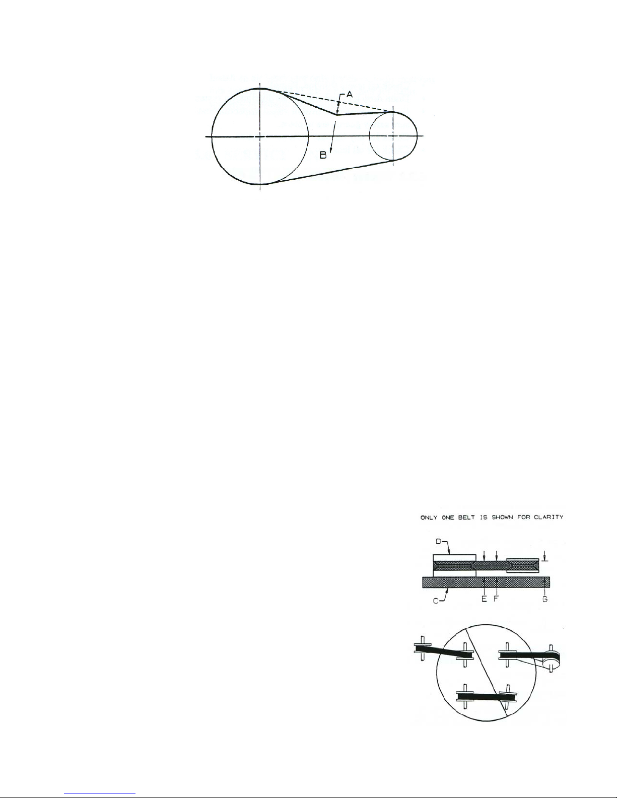
life. The correct tension exists if a deflection (see A in Figure 5 on the next page) of ½” (13 mm)
occurs by placing 10 lb (4.4 kg) of force (see B in Figure 5 on the next page) midway between the
motor pulley and the pump flywheel. This deflection can be adjusted by the following procedure.
22
Page 23
6.2.3 PULLEY ALIGNMENT & BELT TENSION (for items 8093262 & 8186751) cont’d
1. Belt Tension (cont’d)
1/2” Deflection
10 Lbs Force
Figure 6: Pulley Alignment
a) Remove the belt guard.
b) Loosen the pump mounting bolts.
c) Shift the pump to the point where the correct deflection exists.
d) Retighten the pump mounting bolts.
e) Check to ensure that the tension remained correct.
f) Reinstall the belt guard. All moving parts must be guarded.
The size of the belt guard limits how much the pump can be moved to adjust the belt tension.
There is approximately 0.5” clearance for each pulley to the inside of the belt guard upon
installation. NOTE: the pulleys should have a minimum clearance of 3/16” (.188” ) at all times.
2. Pulley Alignment
To check pulley alignment, remove the belt guard and place a straightedge (C in Figure 6 below)
against the pump pulley (D in Figure 6 below). Measure and record the distance from the straightedge
to the edge of the drive belt (dimension E). Then measure the distance from the straightedge to the
edge of the drive belt again as shown by dimensions F and G. Both distances should be the same as
dimension E. If F or G is different from E, there is a misalignment that must be corrected before the
pressure washer is run. To correct a pulley misalignment, use the following procedure.
a) Remove the belt guard.
b) Loosen the pump mounting bolts.
c) Loosen the bolts on the engine or pump pulley bushing (which
ever is easier to work with – the pump shaft is relatively short).
d) Align the engine pulley with the pump pulley (E=F=G).
e) Retighten the bolts on the engine or pump pulley bushing.
f) Adjust the proper belt tension.
g) Retighten the pump mounting bolts.
h) Reinstall the belt guard. All moving parts must be guarded.
Figure 5: Belt Tension
23
Page 24

7. TROUBLESHOOTING
PROBLEM CAUSE SOLUTION
Engine won’t run. No fuel.
Carburetor out of adjustment.
Low-oil shutdown is shutting off
engine.
Pressure Loss. Unloader valve has been
loosened (turned counterclockwise).
Hose inlet filter clogged.
Air in water.
Nozzle worn.
Pump worn.
No water at nozzle. Water tap turned off.
Hose inlet filter-washer
completely plugged.
Plugged nozzle.
Spray pressure fluctuates. Air in water inlet line.
Insufficient water flow.
Worn pump.
Maladjusted unloader valve.
Will not draw sufficient
detergent of fails to draw at
all.
Water flows into detergent
container as soon as water
hose is turned on.
Noisy operation, knocking. Worn or broken bearing.
Irregular spray pattern. Pump is not primed.
Excessive belt wear. Pulley out of alignment.
Detergent hose foot strainer
plugged.
Air in detergent.
Injector is clogged.
Low pressure nozzle is clogged
or worn.
Injector ball valve remains
open.
Inadequate water supply to
pump.
Worn or partially clogged
nozzle.
Improper belt tension.
Pulley wobbles.
Add fuel.
Refer to Engine Operator’s Manual.
Add oil to proper level as indicated on
dipstick.
Turn unloader clockwise until it locks at
original factory preset position.
Remove and clean.
Tighten all water hose fittings.
Replace nozzle.
Rebuild or replace pump.
Turn on water.
Remove and clean.
Clear obstruction by blowing air back
through nozzle.
Tighten all garden hose fittings.
Increase water source capability.
Rebuild or replace pump.
Readjust unloader to original factory preset.
Remove from container and clean.
Check for air leaks in detergent hose and
fix.
Remove and clean injector.
Clean low pressure nozzle or replace.
Dismantle injector and clean.
Replace bearing as needed.
Ensure adequate water supply. Clear inlet.
Prime pump.
Clean or replace spray nozzle.
Realign pulleys.
Adjust tension.
Replace the pulley and check for a
damaged crankshaft or pulley.
24
Page 25

8. SPECIFICATIONS
Model #
Part #
FRAME
Height (in.)
Width (in.)
Length (in.)
ENGINE
Type
Power (HP)
Speed (RPM)
PUMP
Type
Pressure (PSI)
Volume (GPM)
Unloader Valve
Injector Valve
Nozzle
Hose (ft.)
Weight, empty
(LBS)
2525DA
8102477
25.00
20.00
36.00
DUCAR
Low oil shutdown
6.5
3600
A.R.
Axial
2500
2.5
Adjustable
Fixed
2 quick
disconnect
nozzles
30
88
2722HC
8038317
36.00
20.00
21.00
HONDA
GX
5.5
3600
COMET
3 Piston
2200
2.7
Adjustable
Adjustable
2 quick
disconnect
nozzles
30
92
2722HA
8186322
36.00
20.00
21.00
HONDA
GX
5.5
3600
A.R.
3 Piston
2200
2.7
Adjustable
Adjustable
2 quick
disconnect
nozzles
30
92
3032HC
8038382
36.50
22.00
28.00
HONDA
GX
9
3600
COMET
3 Piston
3200
3.0
Adjustable
Adjustable
2 quick
disconnect
nozzles
30
125
25
Page 26

8. SPECIFICATIONS (cont’d)
Model #
Part #
FRAME
Height (in.)
Width (in.)
Length (in.)
ENGINE
Type
Power (HP)
Speed (RPM)
PUMP
Type
Pressure (PSI)
Volume (GPM)
Unloader Valve
Injector Valve
Nozzle
Hose (ft.)
Weight, empty
(LBS)
3032HA
8186306
36.50
22.00
28.00
HONDA
GX
9
3600
A.R.
3 Piston
3200
3.0
Adjustable
Adjustable
2 quick
disconnect
nozzles
30
125
3536HA
8093254
27.00
29.00
41.25
HONDA
GX
11
3600
A.R.
3 Piston
3600
3.5
Adjustable
Adjustable
4 quick
disconnect
nozzles
50
165
4036DA
8093247
27.00
29.00
41.25
DUCAR
Low oil shutdown
13
3600
A.R.
3 Piston
3600
4.0
Adjustable
Adjustable
4 quick
disconnect
nozzles
50
165
4036HA
8093270
27.00
29.00
41.25
HONDA
GX
13
3600
A.R.
3 Piston
3600
4.0
Adjustable
Adjustable
4 quick
disconnect
nozzles
50
165
26
Page 27

8. SPECIFICATIONS (cont’d)
Model #
Part #
FRAME
Height (in.)
Width (in.)
Length (in.)
ENGINE
Type
Power (HP)
Speed (RPM)
PUMP
Type
Pressure (PSI)
Volume (GPM)
Unloader Valve
Injector Valve
Nozzle
Hose (ft.)
Weight, empty
(LBS)
4036HC
8093262
27.00
29.00
46.50
HONDA
GX
13
3600
COMET
3 Piston
3600
4.0
Adjustable
Adjustable
4 quick disconnect
nozzles
50
176
4036HA
8186751
27.00
29.00
46.50
HONDA
GX
13
3600
A.R.
3 Piston
3600
4.0
Adjustable
Adjustable
4 quick disconnect
nozzles
50
176
27
Page 28
9. ASSEMBLY PART LISTS
MODEL #2525DA
PARTS LIST
ITEM #8102477
CONSUMER CLASS
29
21
10
12
5
17
14
32
25
27
2
13
28
16
30
3
18
31
15
24
22
23
1
19
20
6
4
11
8
26
14
9
7
28
Page 29

PARTS LIST
MODEL #2525DA
ITEM #8102477
CONSUMER CLASS
No. Item No. Description Qty
1 1900040 BASE S/ASSY - SILVER 1
2 10002753 ENGINE 6.5 HP DUCA R 1
3 10002641 PUMP AR 2.5 GPM X 2500 PSI PRE-SET 1
4 1900041 HANDLE - SILVER 1
5 9253204 AXLE PRESSURE WASHERS 1
6 9232802 HAND GRIP FOR 1" SQ TUBING 1
7 9212572 GUN SPRAY 2500 PSI X 7 GPM 1
8 10002069 LANCE SPRAY .25 NPTM X 18" LG 1
9 9253386 RUBBER TIP 1 1/8" RD 1
10 2020060 WHEEL 4.10/3.50-4 X .625 AXLE 2
11 10003341 WASHER PTD .625 ID X 1.125 OD X .074 THK 2
12 9860081 COTTER PIN .109 X 1.50 PLATED 2
13 9236241 BOLT HEX SERRATED FLANGE .312-18UNC X 2.50 LG GR 5 PTD 2
14 9229691 NUT HEX SERRATED FLANGE .312-18 UNC 6
15 9160813 DECAL PAL SERIAL # 1
16 9161589 DECAL CAUTION OIL LEVEL 1
17 9160961 DECAL WARNING UNLOADER 1
18 1900016 STRAINER CHEMICAL 1
19 4210659 CABLE TIE NYLON 6" 1
20 9162488 TAG MAINTENANCE 1
21 9229683 BOLT HEX SRD FLANGE .312-18 UNC X 1.50 4
22 9853342 WASHER LOCK SPLIT REG .312 PTD 4
23 10002809 BOLT HEX M8 X M1.25 X 25.4 LG GR 8.8 PLTD 4
24 8006025 SCR TYPE QUICK DIS. M22F X .375 GF 1
25 9233073 GROMMET RUBBER .44 ID X .94 OD X .38 4
26 5710209 NOZZLE 25030 QUICK CHANGE 1
27 5710611 NOZZLE 50 DEG LOW PRESSURE CHEMICAL INJECTION 1
28 10002757 DECAL POWERFIST 2.5 GPM X 2500 PSI 1
29 9226788 HOSE W/PROTECTOR .375 ID X 30' 1
30 9235391 HOSE CLEAR .25 ID X .375 OD X 60" LG 1
31 10002738-2 DECAL RISK OF BURNS/BREATHING 1
32 9160359 DECAL WARNING HP FLUIDS 1
29
 Loading...