

Powerfist 5E-1-60V, 5E-2-80V, 10E-2-120H-3-230, 10E-2-120H-1-230, 10E-2-120H-3-575 User Manual

TABLE OF CONTENTS
SECTION PAGE
1 GENERAL INFORMATION 2
2 SAFETY GUIDELINES 5
3 OPERATION 7
3.1 How the Compressor Works 7
3.1.1 Components 7
3.1.2 Controls 8
3.1.3 Inlet Air System 8
3.1.4 Discharge System 9
3.2 Assembly 11
3.3 Pre-Operation Checklist 11
3.4 Break-in and Startup 12
3.5 Daily Starting Checklist 12
4 MAINTENANCE 13
4.1 Maintenance Safety 13
4.2 Servicing Intervals 13
4.3 Pump Lubricant 14
4.4 Pulley Alignment and Belt Tension 14
4.5 Bolt Torque Specifications 16
5 TROUBLESHOOTING 17
6 AIR COMPRESSOR SPECIFICATIONS 19
7 ASSEMBLY PART LISTS 22
8 PUMP PART LISTS 44
1

1. GENERAL INFORMATION
Congratulations on your choice of a Powerfist Compressor. This equipment has been designed and
manufactured to meet the light industrial and consumer needs of air compressors.
Safe, efficient and trouble free operation of your Compressor requires that you and anyone else who will be
operating and maintaining the machine, read and understand all of the safety, operation maintenance and
troubleshooting information contained within this Operator’s Manual.
WARRANTY- PARTS - SERVICE
If you experience any problems and need assistance or parts and repair service please contact Princess Auto
Ltd. at:
Telephone # 1-800-665-8685 Fax # 1-800-265-4212
To obtain prompt, efficient service, always provide the serial number and item number of your unit. See the
parts list for location of the serial number decal. Please mark the numbers in the space provided for easy
reference.
SERIAL # ________________________
ITEM # ________________________
Printed in Canada 10002216-1
Issue Date: June 2010 Revision 12
2
IMPORTANT
The compressor tank is an ASME certified pressure vessel. The CRN and manufacturer’s information is
stamped on the tank nameplate. A certification document with the corresponding serial number is provided
with this manual for every compressor tank. Provincial jurisdictions require compressors to be registered with
Departments of Labour upon installation. Below is a list of Provincial jurisdictions that handle registration. It is
the customer’s responsibility to contact these offices and obtain registration.
Note: All registrations for Atlantic Provinces are handled by ACI Central P.E.I.
Technical Committee on Boilers & Pressure Vessels
Jurisdiction Chief Inspector/Contact
Ministry of Municipal Affairs
Safety Engineering Division
Design Survey Dept.
88 - 6th Street Suite 400
New Westminster, BC V3L 5B8
Alberta Boiler Safety Association
#200, 4208 – 97 Street
Edmonton, AB T6E 5Z9
Saskatchewan Municipal Services
Protection Services Branch
Boiler & Pressure Vessel Safety
330 – 1855 Victoria Ave.
Regina, SK S4P 3V7
Department of Labour & Manpower
Mechanical & Engineering
500 – 401 York Ave.
Winnipeg, MB R3C 0P8
Technical Standards Safety Authority
3300 Bloor Street West
th
Floor, West Tower
4
Etobicoke, ON M8X 2X4
Regie du Batiment du Quebec
Service de L’inspection de la Fabrication
d’appareils sous pression
545 Boul Cremazie est, 4 etage
Montreal, QC H2M 2V2
Department of Labour & Manpower
Technical Services Branch
PO Box 6000
Fredericton, NB E3B 5H1
Department of Labour
Boiler Inspection Branch
Box 2000, 68 University Avenue
Charlottetown, PEI E3B 5H1
Department of Labour & Manpower
Occupational Safety Division
5151 Terminal Road, 6th Floor
PO Box 697, Halifax, NS B3J 2T8
Government of Newfoundland & Labrador
Department of Government Services and Lands
5 Mews Place, PO Box 8700
St. John’s, NFLD A1B 4J6
ACI Central (for all registrations in NB, NS, PEI, NFLD)
20 McAulay Court, PO Box 53
Charlottetown, PEI C1A 9M7
S. Katz
Ph: (604) 660-6254
Fax: (604) 660-3460
K.T. Lau, Chair
B. McWhirter
Ph: (780) 437-9100
Fax: (780) 437-7787
N. Surtees
Ph: (306) 787-4522
Fax: (306) 787-9273
I.W. Mault
Ph: (204) 945-3373
Fax: (204) 948-2309
R. Mile
C. Turylo
Ph: (416) 325-2000
Fax: (416) 326-8248
R. Awad
M. Kotb
Ph: (514) 837-6459
Fax: (514) 837-6459
D.E. Ross
See ACI Central
K. Hynes
See ACI Central
Charles J. Castle
Ph: (902) 424-7527
Fax: (902) 424-3239
See ACI Central
D. Eastman
Ph: (709) 729-2747
Fax: (709) 729 2071
See ACI Central
Krista Cudmore
Ph: (902) 566-3133
Fax: (902) 566-3133
3

Jurisdiction Chief Inspector/Contact
Department of Municipal & Community Affairs
Protective Services
PO Box 2703, 2701 Second Ave.
Main Administration Building
Whitehorse, Yukon Y1A 2C6
Government of the Northwest Territories
Department of Public Services, Safety Division Boiler &
Pressure Vessel Branch
4916-49
Yellowknife, NWT X1A 2L9
Government of Nunavut
Public Works & Services
Kitikmeot region
Bag Service 200
Cambridge Bay, Nunavut X0B 0C0
th
Street, Northway Building
Dan Price
S. Donovan
B. Bachellier
Ph: (867) 983-4152
4
2. SAFETY GUIDELINES
DEFINITIONS
Safety symbols identify important safety messages that alert to the possibility of personal injury or death.
Review them carefully before operating the unit and before performing maintenance or repairs. Check the rules
and regulations at your location and identify possible hazards. The appropriate signal word for each message
has been selected using the following guidelines:
- Danger indicates an immediate and specific hazard, which will result in severe personal
injury or death if the proper precautions are not taken.
- Warning indicates a specific hazard or unsafe practice, which could result in severe
personal injury or death if proper precautions are not taken.
- Caution indicates a potentially hazardous situation, which may result in minor or moderate
injury if proper practices are not taken.
____________________________________________________________________________
IMPORTANT SAFETY INSTRUCTIONS
Read and understand the operator’s manual and all safety alerts before
operating or maintaining your Compressor. Be certain that everyone operating this
equipment is familiar with the recommended operating and maintenance procedures
and follows all the safety precautions. Never let children or untrained adults operate
the machine.
_______________________________________________________________________________
RISK OF FIRE OR EXPLOSION
Never spray flammable liquids in a confined area. It is normal for the motor and pressure switch to produce
sparks while operating. If sparks come into contact with vapors from gasoline or other flammable solvents,
they may ignite, causing a fire or an explosion. Always operate the compressor in a well-ventilated area as far
from spray area as possible.
RISK OF BURSTING
Air under pressure will cause injury, death or property damage. Do not exceed pressure rating. Safety relief
valve settings must not be changed, check regularly for proper operation. Do not weld, drill or modify
compressor tank; it can severely impair tank strength and cause extremely hazardous conditions. Any
adjustment by user will void the warranty.
RISK OF INJURY
Do not operate with belt guard removed. Wait for all moving parts to stop before removing belt guard for
compressor servicing. Belt guard must be fastened in place before starting the compressor.
RISK OF ELECTRICAL SHOCK
All electrical enclosures, cables, wiring and components must be installed and grounded in accordance with
national and local electrical code.
ALL WIRING MUST BE DONE BY A LICENSED ELECTRICIAN.
in personal injury or damaged components.
Failure to comply could result
5

2. SAFETY GUIDELINES
(cont’d)
RISK OF BURNS
High temperatures are generated by the operation of the compressor. Contact with hot surfaces, such as the
pump or discharge hose could result in a serious burn. Allow them to cool off before handling or servicing.
Keep children away from the compressor at all times.
RISK TO BREATHING
Toxic, volatile and corrosive vapors can cause personal injury. Provide adequate ventilation. Never directly
inhale compressed air produced by a compressor. It is not suitable for breathing purposes. Read all labels
when you are spraying paints or toxic chemicals and follow the safety instructions.
RISK OF HEARING AND EYE INJURY
Always wear hearing protection and approved safety goggles when using an air compressor. Failure to do so
may result in hearing loss and serious injury.
6
3. OPERATION
3.1 HOW THE COMPRESSOR WORKS
3.1.1 COMPONENTS
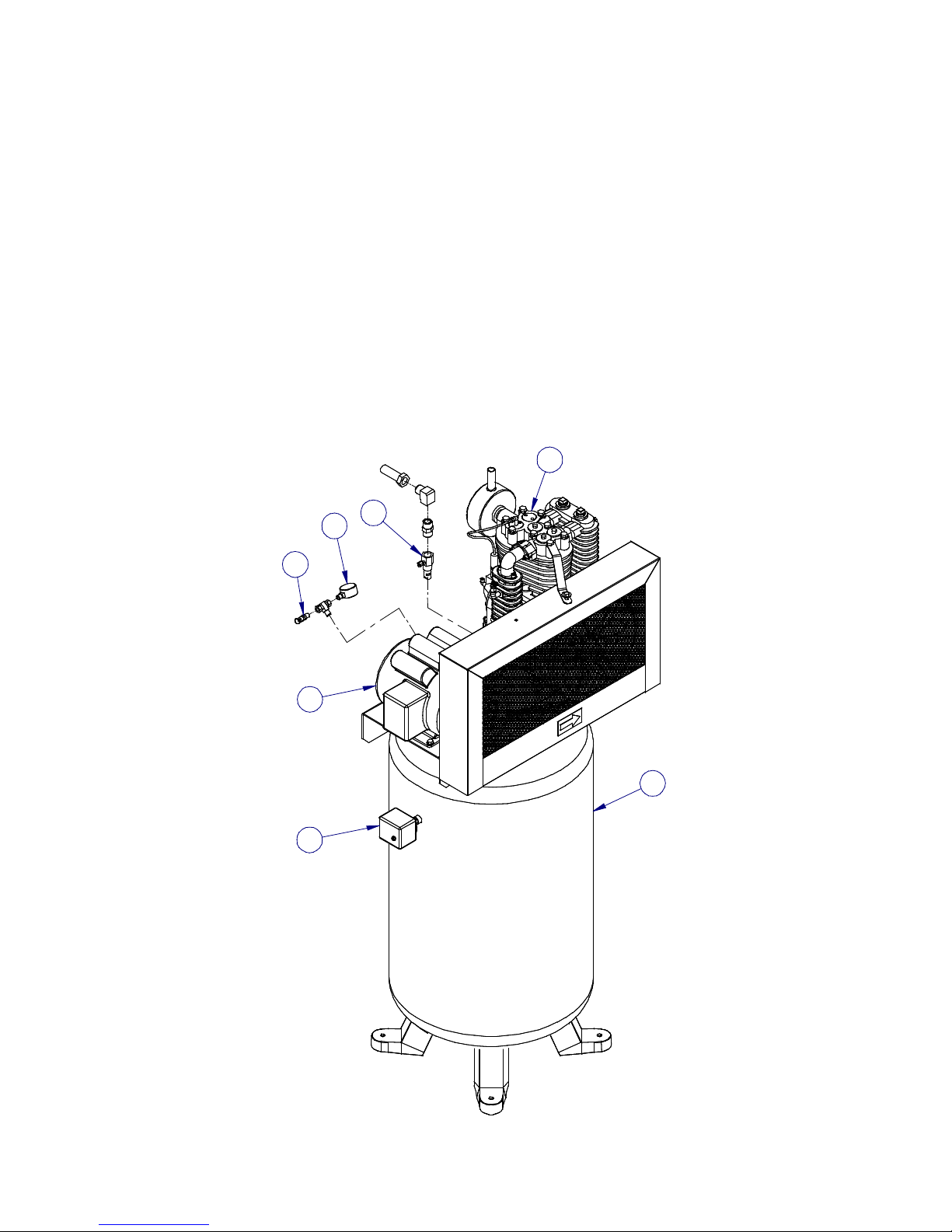
The basic components of the air compressor are the electric motor, pump, tank and pressure switch. The
motor (item A) powers the pump. The motor drives a pulley and belt, which transfers power from the motor to
the pump pistons via a flywheel and a crankshaft. The flywheel fan helps cool the pump.
The pump (item B) compresses the air and discharges it into the tank. As the piston in the pump cylinder
moves downward, air enters the cylinder through the filter and air intake valves at atmospheric pressure. As
the piston moves upward, it compresses the air and discharges it into the tank through an unloader/check
valve.
The tank (item C) stores the compressed air. A check valve at the tank inlet prevents the compressed air in
the tank from flowing back into the pump.
The pressure switch (item D) shuts down the motor when the air pressure in the tank reaches the kick-out
pressure. As compressed air is used and the pressure level in the tank drops to the kick-in pressure, the
pressure switch restarts the motor automatically, without warning, and the pump resumes compressing air.
A Motor
B Pump
C Tank
D Pressure Switch
E Relief Valve
F Pressure Gauge
G Check Valve
G
F
E
B
A
D
Figure 1: Air Compressor Components
C
7

3.1.2 CONTROLS
1. Check Valve
Check valves (item G in Figure 1, page 5) are designed to prevent backflow of air pressure in the
compressed air system (i.e. air flows freely in one direction only).
2. Pressure Relief Valves
The pressure relief valve (item E in Figure 1, page 5) aids in preventing system failures by relieving
pressure when compressed air reaches a determined level. They are available in various pressure
settings. Pressure relief valves are pre-set by the manufacturer and under no circumstances should
the setting be changed by anyone other than the manufacturer. All pressure relief valves must be
tested on a regular basis and kept clean by pulling the ring connector on the end of the valve.
3. Pressure Switch
The pressure switch detects the demand for compressed air and allows the motor to start. When the
system pressure reaches a set limit, the motor is shut off. Pressure switches provided, are pre-set at
the factory and should not be adjusted. WARNING! Never exceed the designed pressure for the
system or overload the motor beyond the amperage rating on the motor label.
3.1.3 INLET AIR SYSTEM
A clean, cool and dry air supply is essential to the satisfactory operation of your compressor. The standard air
filter that the compressor is equipped with when leaving the factory is of sufficient size and is designed to meet
normal conditions, when properly serviced in accordance with the maintenance section of this manual.
If however the compressor is to be installed in a location where considerable dust, dirt and other contaminants
are prevalent, consult your local Distributor for advice. It is the user’s responsibility to provide adequate
filtration for these conditions. Oil bath filters are not to be used.
CAUTION: Never locate the compressor where toxic, volatile or corrosive vapors, air temperatures
exceeding 100 degrees F, water, or extremely dirty air could be ingested. The performance of the
compressor system could be adversely affected.
8

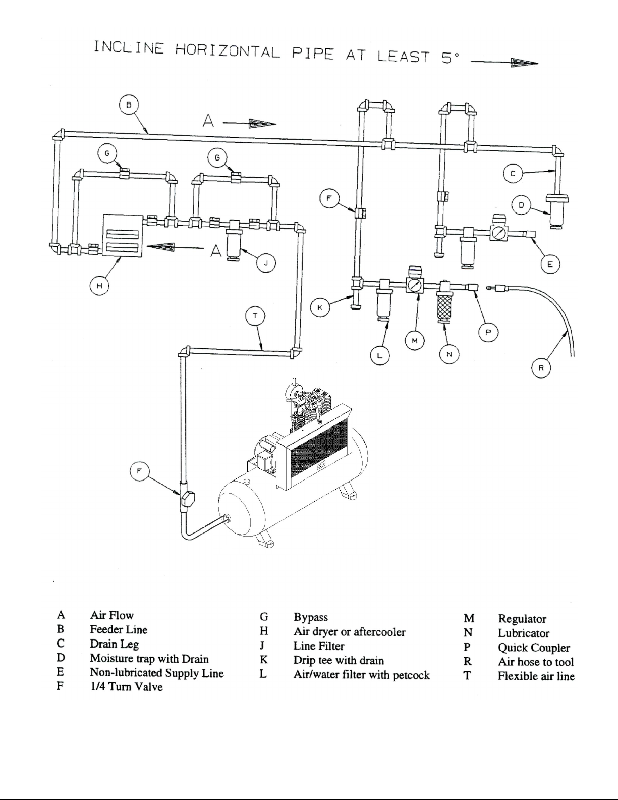
3.1.4 DISCHARGE SYSTEM
1. Discharge Pipe
The discharge piping should be of the same diameter as the compressor discharge connection, or
sized so that the pressure drop at any point in the system does not exceed 10% of the air receiver
pressure.
2. Auxiliary Air Receiver
Install auxiliary air receivers near heavy loads or at the far end of a long system. This will ensure
sufficient pressures if the use is intermittent, or sudden large demands are placed on the system.
3. Moisture Removal and Air Filtration
As the air cools, moisture will condense in the line. This moisture must be removed before it reaches
the tool being used. To remove this moisture, run the main air line downhill to a moisture trap and
drain. All service line outlets should be installed above the moisture trap to prevent moisture from
entering the tool or device used with the air.
4. Shut-off Valves
Install shut-off valves in each drop line to isolate the tool and its accessories for servicing. You can
also install a bypass line around an accessory.
5. Air Receiver Tank
An air receiver tank stores the compressed air. WARNING! Pressure vessels must not be
modified, welded, repaired, reworked or subjected to operating conditions outside the
nameplate ratings. Such actions may cause property damage, severe injury or even death.
6. Drain Valve
A drain valve must be located in the bottom of the air receiver tank to allow for moisture drainage.
7. Air Pressure Gauge
The air pressure gauge on the tank measures air pressure inside the tank. Install the air pressure
gauge in the drop line for each tool to regulate air pressure to the tool. Never exceed the maximum
pressure rating.
8. Air Lubrication
Install an air lubricator only for those tools requiring lubrication. DO NOT
spraying or similar applications.
use a lubricator for paint
9
10
Figure 2: Compressor Air System

3.2 ASSEMBLY
1. Unpack the air compressor. Inspect the unit for damage. If the unit has been damaged in transit
complete a damage claim.
2. Check the compressor’s item number to confirm you have received the model ordered.
3. Ensure that adequate lifting equipment is available for moving the compressor. Follow good shop
practices and safety procedures.
4. If necessary for your model install rubber feet provided in the kit.
CAUTION! The shipping pallet is not designed as a base for an operating compressor. Remove
the compressor from the pallet and place it on the floor or a hard, level surface. The compressor must
be level to ensure proper lubrication of the pump and good drainage of the moisture in the tank. We
recommend the use of rubber vibration pads under the feet for stationary units.
5. The flywheel side of the compressor must be at least 12 inches (31cm) from any wall or obstruction in
a clean, well-ventilated area to ensure sufficient air flow and cooling.
6. Connect discharge system components (not included) to the tank outlet.
7. IMPORTANT! All wiring information is stated on the electric motor and on the pressure switch, or
provided with the magnetic starter (sold separately). Princess Auto cannot, by law, provide the
customer with any additional wiring information.
3.3 PRE-OPERATION CHECKLIST
1. Remove all loose pieces and installation tools from the compressor and check for installation debris.
2. Unless otherwise specified, compressors are normally shipped without lubricant in the crankcase. Add
the correct amount of specified oil to the crankcase of the pump.
3. Check motor and compressor pulleys for alignment and tightness on shaft.
4. Manually rotate the compressor pulley several rotations to be sure there are no mechanical
interferences.
5. Check belt tension.
6. Check all pressure connections for tightness and leaks.
7. Make sure all pressure relief valves are correctly installed.
8. Be sure all guards are in place and securely mounted.
9. Check fuses, circuit breakers and thermal overloads for proper ratings.
10. Open all manual shutoff valves at and beyond the compressor discharge.
11. After all the above conditions have been satisfied, the unit can be connected to the proper power
source.
12. Jog the starter switch to check the rotational direction of the compressor. It should agree with the
rotation arrow embossed on the compressor pulley.
11

3.4 BREAK-IN & START-UP
This instruction manual, as well as any instructions supplied by the manufacturers of supporting equipment,
should be read and understood prior to starting the compressor. With the pre-operation checklist completed
and satisfied proceed to start the compressor.
1. Check oil level in the crankcase. The oil level should be no lower than the center of the sight glass.
2. Check that the drain cock is open.
3. Start compressor and watch for excessive vibrations and/or strange noises. If either exists, stop the
compressor. Refer to troubleshooting for help in determining the cause of such problems.
4. Manually activate safety relief valves by pulling ring or lever.
5. Run the compressor unloaded for 20 minutes to lubricate and break-in the internal parts.
6. Close the drain cock. Compressor will fill the tank to the cut out pressure.
7. Check the operation of controls and system pressure.
8. Observe compressor operation closely for the first hour and then frequently for the next 8 hours of
operation.
9. After the first 8 hours of operation change the oil, check the belt tension and inspect the system for leaks.
WARNING! - High temperatures are generated by the operation of the compressor. Contact with hot
surfaces, such as the pump or discharge hose could result in a serious burn. Allow them to cool off
before handling or servicing. Keep children away from the compressor at all times.
3.5 DAILY STARTING CHECKLIST
Do not proceed until the Pre-Operation Checklist and Break-In & Start-Up sub-sections have been read and
are thoroughly understood.
1. Check oil level in the crankcase of compressor pump. Ensure level is at the center of the sight glass.
2. Drain liquid from the air receiver and moisture trap.
3. Start compressor as per factory instructions.
4. Check system pressure.
5. Check all pressure relief valves for proper operation.
6. Check control system for proper operation.
12

4. MAINTENANCE
4.1 MAINTENANCE SAFETY
1. Turn off motor and relieve pressure before servicing
2. Open all manual drain valves within the area to be serviced.
3. Isolate the compressor from the compressed air supply by closing a manual shutoff valve upstream
and downstream from the compressor. Display a sign in clear view at the shutoff valve stating that the
compressor is being serviced.
4. Lock open a pressure relief valve within the pressurized system to allow the system to be completely
de-pressurized. NEVER remove a plug to relieve the pressure!
5. Wait for the unit to cool before starting to service. Temperatures of 125F can burn skin. Some
surface temperatures exceed 350F when the compressor is operating.
4.2 SERVICING INTERVALS
1. Before and / or After Use
a) Check pump oil level.
b) Drain drop legs and traps in air distribution system.
c) Manually operate the pressure relief valves.
d) Give compressor an overall visual inspection and be sure safety guards are in place.
e) Check for any unusual noise or vibration
Check for oil leaks
f)
2. 50 Hours or Every Two-Weeks Service
a) Inspect the air filter for contamination. Replace the air filter often to ensure a clean air supply to
the compressor pump.
b) Clean the cooling surfaces of the intercooler and compressor.
c) Check the compressor for air leaks.
d) Check the compressed air distribution system for leaks.
Inspect oil for contamination. Change more often under humid or dirty conditions.
e)
3. Monthly to Quarterly (160 – 500 hours)
a) Check belt tension and pulley alignment.
b) Change pump oil (more frequently in harsher environments).
c) Tighten any loose bolts or sheave fasteners. Check the overall operation of the unit.
4. 6 Months (1000 hours)
a) Inspect compressor valves for leakage and/or carbon build-up.
.
13

4.3 PUMP LUBRICANT
1. Oil Level
Always operate the unit in a level position. Prior to start-up, check the sight glass to ensure the oil in
the pump is at the required level. If the oil level is too low, remove the oil fill plug and add oil until the
level is at the center of the sight glass. For approximate oil requirements, see pages 16-17. Do not
overfill or under fill as it could damage the pump. CAUTION! The oil level in the pump crankcase
must be checked daily.
2. Oil Type
The correct lubricant is essential to the proper operation of your compressor. For single stage or 2stage compressors, use ISO 68, SAE 25 weight oil. This compressor oil is available at your local
Princess Auto store. CAUTION! Do not use motor oil in the compressor pump.
3. Condensation
Water condensing in the crankcase can occur under certain humid conditions or light duty cycling.
This water must be removed from the pump to prevent damage. Drain the oil and refill.
Condensation can be prevented by allowing the pump to reach its normal operating temperature by
releasing air from the tank and allowing the pump to run, or by using more air, which will cause the
pump to operate more frequently. CAUTION! A rise in the oil level and a milky color indicates that
condensation is forming in the crankcase. This condensation must be drained immediately or the
pump may be damaged.
4.4 PULLEY ALIGNMENT & BELT TENSION
Improper pulley alignment and belt tension are causes for motor overloading, excessive vibration and
premature belt or bearing failure. To prevent this from happening, check the pulley alignment and belt tension
on a regular basis.
Periodically, inspect both the motor and compressor pulleys for oil, grease, nicks or burrs. Clean or replace
pulleys if necessary. Make sure the pulleys are securely fastened. Align the compressor pulley with motor.
The drive belt grooves of both pulleys should be in line with each other. The compressor crankshaft must be
parallel to the motor shaft.
WARNING! To avoid personal injury, always shut off main power disconnects for the compressor and
relieve all air pressure from the system before performing any service on the air compressor.
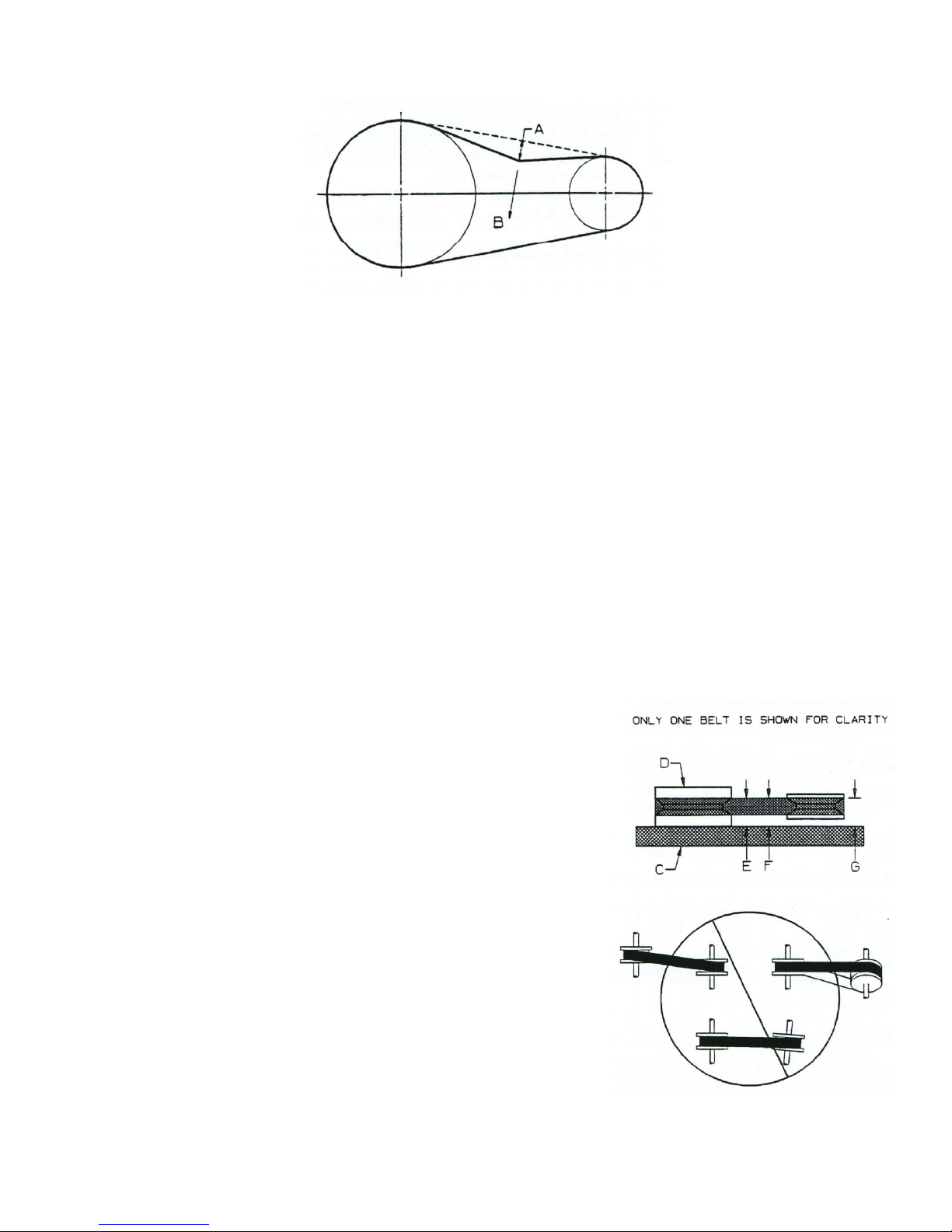
1. Belt Tension
Proper belt tension and pulley alignment must be maintained for maximum drive efficiency and belt
life. The correct tension exists if a deflection (see A in Figure 3 on the next page) of ½” (13 mm)
occurs by placing 10 lb (4.4 kg) of force (see B in Figure 3 on the next page) midway between the
motor pulley and the pump flywheel. This deflection can be adjusted by the following procedure. The
pulley should be carefully aligned with the flywheel and all setscrews should be kept tight.
14
4.4 PULLEY ALIGNMENT & BELT TENSION (cont’d)
1/2” Deflection
10 Lbs Force
1. Belt Tension (cont’d)
Figure 3: Belt Tension
a) Remove the belt guard.
b) Loosen the motor mounting bolts.
c) Shift the motor to the point where the correct deflection exists.
d) Retighten the motor mounting bolts.
e) Check to ensure that the tension remained correct.
f) Reinstall the belt guard. All moving parts must be guarded.
2. Pulley Alignment
To check pulley alignment, remove the belt guard and place a straightedge (C in Figure 4 below)
against the pump flywheel (D in Figure 4 below). Measure and record the distance from the
straightedge to the edge of the drive belt (dimension E). Then measure the distance from the
straightedge to the edge of the drive belt again as shown by dimensions F and G. Both distances
should be the same as dimension E. If F or G is different from E, there is a misalignment that must be
corrected before the compressor is run. To correct a pulley misalignment, use the following
procedure.
a) Remove the belt guard.
b) Loosen the motor mounting bolts.
c) Loosen the setscrew on the motor pulley.
d) Align the motor pulley with the pump flywheel (E=F=G).
e) Retighten the motor pulley setscrew.
f) Adjust the proper belt tension.
g) Retighten the motor mounting bolts.
h) Reinstall the belt guard. All moving parts must be guarded.
Figure 4: Pulley Alignment
15

4.5 BOLT TORQUE SPECIFICATIONS
The table shown below gives the correct torque values for various bolts and cap screws. Tighten all bolts to
the torque values specified unless otherwise noted. Periodically check the torque values of all fasteners using
the table as a guide. Replace hardware with the same strength materials.
Bolt
Diameter (in)
N/m ft-lbs N/m ft-lbs N/m ft-lbs
1/4 8 6 12 9 17 12
5/16 13 10 25 19 36 27
3/8 27 20 45 33 63 45
7/16 41 30 72 53 100 75
1/2 61 45 110 80 155 115
9/16 95 70 155 115 220 165
5/8 128 95 215 160 305 220
3/4 225 165 390 290 540 400
7/8 230 170 570 420 880 650
1 345 225 850 630 1320 970
SAE Grade 2 SAE Grade 5 SAE Grade 8
16

5. TROUBLESHOOTING
PROBLEM CAUSE SOLUTION
Excessive motor current draw. Low voltage/motor overload. Check that power supply is adequate and that
compressor is on a dedicated circuit.
Compressor Stalls. Low voltage to motor.
Seized pump.
Low discharge pressure. Air leaks.
Restricted air intake.
Leaking valves.
Blown gaskets.
Worn piston rings or cylinder.
Defective pressure switch.
Drive belt slipping.
Defective pressure gauge.
Compressor pump knocking. Loose motor pulley or compressor
flywheel.
Low oil level in pump crankcase.
Excess carbon on valves on top of
piston.
Worn connector rod at wrist pin
end.
Oil in discharge air. Worn piston rings or cylinder.
Restricted air intake.
Oil level too high.
Overheating. Poor ventilation.
Dirty cooling surfaces.
Clogged intake system.
Inadequate lubrication.
Restricted air passages.
Pulley rotation wrong.
Excessive belt wear. Pulley out of alignment.
Improper belt tension.
Pulley wobbles.
Furnish adequate power.
Contact authorized service center.
Tighten or replace leaking fittings or connections.
Do not over-tighten.
Clean or replace air filter element(s).
Contact authorized service centre.
Contact authorized service centre.
Contact authorized service centre.
Contact authorized service centre.
Adjust drive belt.
Replace gauge.
Tighten pulley and flywheel. Check alignment.
Keep oil level full at all times.
Contact authorized service centre.
Contact authorized service centre.
Contact authorized service centre.
Clean or replace the air filter element(s).
Reduce to proper level. Use non-detergent oil.
Relocate compressor to an area with cool, dry,
well circulated air at least 12 in. from the nearest
wall.
Clean all cooling surfaces thoroughly.
Clean/replace intake filter.
Check oil level.
Replace transfer tubes and/or unloader.
Check pulley rotation direction.
Realign pulley with compressor flywheel.
Readjust.
Replace the pulley and check for a damaged
crankshaft or flywheel.
17

PROBLEM CAUSE SOLUTION
Compressor won’t start in cold
temperature.
Low pressure (75 psi) pressure
relief valve opens.
High pressure (225 psi)
pressure relief valve opens.
Motor hums but won’t turn. Low voltage to compressor.
Water in the crankcase. Condensation.
Excessive vibration. Loose pulley.
Excessive oil consumption. Defective breather valve.
Stops shortly after starting. Low voltage causing motor
Stops after running for a while. Compressor or starter overheating. Ventilate compressor room area or remove
Too much back pressure in tank.
No power.
Compressor too cold.
Using wrong grade oil.
Intake valve to high pressure
cylinder is plugged.
Check valve blocked. Clean or replace the check valve.
Compressor starting under
pressure.
Pump or motor not secured.
Foundation or frame inadequate.
Compressor feet are not level.
Wrong grade oil.
Leaking oil seal.
Restricted intake.
overload.
Open drain cock when starting motor.
Check all power sources and circuit.
Move compressor to a warmer location.
Use ISO 1001 30W compressor oil in
temperatures above 30F (-1C) and 10W oil
below 30F (-1C).
Contact authorized service centre.
Motor wired for wrong voltage.
Check head unloader valve system.
Change oil. Run compressor for longer period
until it is hot, ensuring the discharge valve is
open.
Tighten pulley.
Tighten bolts.
Check mounting. Surface should be level and
strong.
Level with shims.
Check breather valve.
Use correct grade of compressor oil.
Replace oil seal.
Check intake system.
See note.*
starter from compressor and mount on wall.
*NOTE – LOW VOLTAGE – Low voltage can cause a multitude of problems. The most common cause of low
voltage is when the wire size (gauge) supplying power to the compressor is too small. The longer the run of
wire, the larger the diameter must be to overcome the inherent voltage loss caused by the wire resistance.
The supply voltage at the main panel could also be low as supplied by your local power company, or you may
have too many other pieces of equipment running off the same line. Your local electrician should be contacted
to evaluate and correct the problem according to the National Electrical Code.
18

6. AIR COMPRESSOR SPECIFICATIONS
Model # 5E-1-60V 5E-2-80V 10E-2-120H-3-230 10E-2-120H-1-230 10E-2-120H-3-575
Part # 8355182 8346645 8346652 8347767 8347783
Tank Capacity (Gal)
Rated (PSI) 175 200 200 200 200
CFM @ 100 PSI 18.5 18 35 35 35
@ 175 PSI 16 16.9 31 31 31
Tank Size
Diameter (in) 20 24 24 24 24
Height/Length (in) 48 48 69 69 69
Plate (in) 25x9x5 18x14x5.5 40x14x4.5 40x14x4.5 40x14x4.5
Pump Model
Compression Stage 1 2 2 2 2
Cylinder 3 2 4 4 4
Oil Required
center of sight glass)
(fill to
60 80 120 120 120
LPW6548ALHI LP205CT LP210CT LP210CT LP210CT
1.6 L 1.5 L 1.9 L 1.9 L 1.9 L
Motor
RPM 3450 1750 1750 1750 1750
Frame R56HZ 184T 215T 215T 215T
Ph 1 1 3 1 3
Volt 230 230 230/460 230/460 575
Amp 20 22 26.8/13.4 38/19 10.3
HP 5 5 10 10 10
Magnetic Starter
Required
Pressure Switch Set 115-140 PSI 135-175 PSI 135-175 PSI 135-175 PSI 135-175 PSI
Range Min/Max 50-175 40-250 PSI 40-250 PSI 40-250 PSI 40-250 PSI
Differential 35/55 25/65 25/65 25/65 25/65
Check Valve Vertical Vertical Vertical Vertical Vertical
Max Pressure Rating 400 PSI 400 PSI 400 PSI 400 PSI 400 PSI
Weight (LBS) 300 554 935 888 935
ODP ODP ODP ODP ODP
No Yes Yes Yes Yes
19

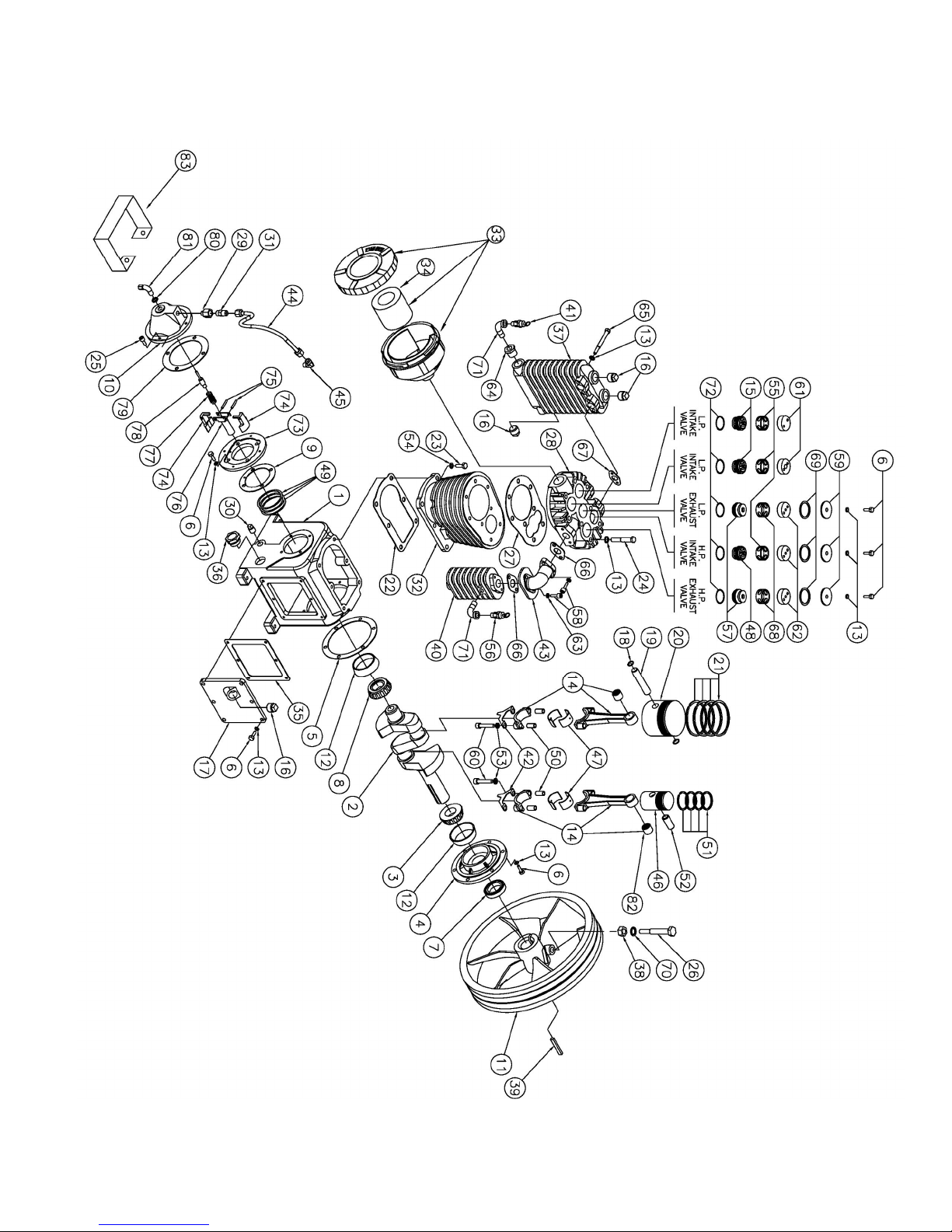
7. ASSEMBLY PART LISTS
COMPRESSOR
5 HP 1 STAGE VERTICAL
MODEL #5E – 1 – 60V
ITEM #8355182
20

COMPRESSOR
2
3
4
5
6
7
8
9
10
11
12
13
14
15
16
17
18
19
20
21
22
23
24
25
26
27
28
29
30
31
32
33
34
35
36
37
38
39
5 HP 1 STAGE VERTICAL
MODEL #5E – 1 – 60V
ITEM #8355182
No. Item No. Description Qty
1 10005698 TANK AIR 60 GAL V. 175 PSI 1
9224656 MOTOR 5 HP 3450 RPM 230V 1 PH 1
10001977 COMPRESSOR HEAD 5 HP 1 STG 3 CYL LPW655 1
9229691 NUT HEX SERRATED FLANGE .312-18 UNC 8
9229683 BOLT HEX SRD FLANGE .312-18 UNC X 1.50 4
9235250 BOLT HEX SER. .312-18UNC X .75 LG 4
9801259 SCREW SET SKT .25-20 UNC 2
9252560 PULLEY AK51 X .876/.877 BORE 1
10002565 BELT V A54 1
9800236 BOLT HEX SERRATED FLANGE .250-20 UNC 4
9226341 NUT HEX SER FLANGE .250-20 UNC 4
10005811 WASHER FLAT .290 ID X 1.25 OD X .0625 4
1291715 NIPPLE HEX .375 NPTM 2
9225681 VALVE .375 NPTF B BODY SS BALL 1
9252511 HOSE DISCHARGE .50 ID X 30" LG 1
9330051 INSERT B COMP .25 X .125 NPTM 2
9255068 TUBE RD NYLON .25 OD X 16.00" LG 1
10002560 TAG BREAK-IN OIL 1
9232141 ELBOW .375 NPT STREET 1
9236548 CAP B. HEX .375 NPTF 1
10005772 DECAL PAL MANUFACTURING 1
10000808 DECAL WARNINGS COMPRESSORS 1
9161365 DECAL DRAIN WATER 1
9161308 DECAL MAINTENANCE COMPRESSORS 1
9160813 DECAL PAL SERIAL # 1
10001981 DECAL 60 GAL SPECIFICATIONS 1
9161340 DECAL ARROW 1
9161563 DECAL WARNING PRESSURE SWITCH 1
10005699-3 BELT GUARD CLIPS 4
10005699 BELT GUARD 2 PIECE 1
10004206 PRESSURE SWITCH 5 HP, 1 PH 230V 1
9234410 ELBOW B .25 NPT STREET 90 1
9252503 RELIEF VALVE 150/160 PSI PRE-SET 1
10005703 PLUG 1/4 COUNTERSUNK HEX HEAD 1
10005846 NIPPLE HEX S .25 NPT X 2.50 LG 1
9236084 GAUGE PRESSURE 0-300 PSI 1
430447 CHECK VALVE VERTICAL .50 NPTM 1
9336074 CONNECTOR B COMPRESSION .25 TUBE X .125 NPTM 1
10003283 ELBOW .50 NPTM X .50 JICM EXT. LG 1
21

COMPRESSOR
5 HP 2 STAGE VERTICAL
MODEL #5E – 2 – 80V
ITEM #8346645
22

COMPRESSOR
5 HP 2 STAGE VERTICAL
MODEL #5E – 2 – 80V
ITEM #8346645
No.
Item No. Description Qty
1 10005940 TANK AIR 80 GAL VER. 200 PSI 1
2 10002222 COMPRESSOR HEAD 5HP 2 STG 1
3 9236068 MOTOR 5 HP 1750 RPM 208-230V 1 PH 1
4 9254426 BRACKET BELT GUARD 5/11 HP COMPRESSOR 1
5 9236316 CHECK VALVE VERTICAL .75 MP 1
6 9238064 ELBOW B .75 NPTM X .75 SAE 1
7 9330085 ELBOW B. .75 NPTF X .75 SAE FLARE 1
8 9238056 HOSE DISCHARGE .75 ID X 20" LG 1
9 10002560 TAG BREAK-IN OIL 1
10 9237207 BUSHING SPLIT TAPERED 1.125" 1
11 9236100 PULLEY DOUBLE GROOVE 7.00 OD B BELT H BUSHINGS 1
12 9800228 BOLT HEX .250-20 UNC X 1.50 LG 2
13 1291756 NIPPLE HEX .75 NPT X .75 NPT 2
14 10005952 REDUCER S .75 MNPT X .5 FNPT 1
15 9310061 NIPPLE B .375 NPT X 4.50 LG 1
16 10005459 PLUG BRASS .125 NPT HEX HEAD 1
17 10005955 VALVE .75 NPTF B BODY SS BALL 1
18 9232141 ELBOW .375 NPT STREET 1
19 9236548 CAP B. HEX .375 NPTF 1
20 3860013 BELT B70 2
21 10005772 DECAL PAL MANUFACTURING 1
22 10000808 DECAL WARNINGS COMPRESSORS 1
23 9161308 DECAL MAINTENANCE INSTRUCTIONS 1
24 10001074 DECAL 80 GAL SPECIFICATIONS 1
25 9160813 DECAL PAL SERIAL # 1
26 10005941 BELT GUARD 80 GAL COMPR. 2 PIECE 1
27 9314824 NIPPLE HEX S .25 X .25 2
28 10005811 WASHER FLAT .290 ID X 1.25 OD X .0625 4
29 9800236 BOLT HEX SERRATED FLANGE .250-20 UNC X .75 LG 4
30 10005971 BOLT HEX SRD FLANGE .312-18 UNC X 2.00 4
31 9229691 NUT HEX SERRATED FLANGE .312-18 UNC 4
32 9239641 BOLT HEX SRD .375-16 UNC 1" LG 4
33 9236183 NUT HEX SER. .375-16 UNC 4
34 9161365 DECAL DRAIN WATER 1
35 9161340 DECAL ARROW 1
36 9161563 DECAL WARNING PRESSURE SWITCH 1
37 9226341 NUT HEX SER FLANGE .250-20 UNC 4
38 10002364 PRESSURE SWITCH 5 HP, 1 PH 230V 1
39 10005893 CROSS S .25 FNPT 1
40 10005947 ELBOW 45 DEG .250 SWIVEL FNPT X MNPT 1
41 9236084 GAUGE PRESSURE 0-300 PSI 1
42 9236118 RELIEF VALVE 200/210 PSI 1
43 10005699-3 1/4 TURN FASTENER 5
23

COMPRESSOR
10 HP 2 STAGE HORIZONTAL
MODEL #10E – 2 – 120H – 3 – 230
ITEM #8346652
24

COMPRESSOR
2
3
4
5
6
7
8
9
10
11
12
13
14
15
16
17
18
19
20
21
22
23
24
25
26
27
28
29
30
31
32
33
4 34
35
36
37
10 HP 2 STAGE HORIZONTAL
MODEL #10E – 2 – 120H – 3 – 230
ITEM #8346652
No. Item No. Description Qty
1 10005879 TANK AIR 120 GAL HOR. 200 PSI 1
10002332 COMPRESSOR HEAD 10 HP, LPCA 210A 2 STAGE 1
9238098 MOTOR 10 HP 1750 RPM 208-230/460V 3PH 1
9238163 HOSE DISCHARGE .75 ID X 30" LG 1
9336090 ADAPTOR B .75 NPTM X .75 SAE FLARE 1
10005892 ADAPTOR S 45 DEG .25 MNPT X .25 MNPT 1
10005893 CROSS S .25 FNPT 1
9236548 CAP B. HEX .375 NPTF 1
10005881 CHECK VALVE VERTICAL .75 NPTM X .75 JIC 1
9161340 DECAL ARROW 1
3850393 PULLEY DBL GROOVE 7.75 OD 1
9238155 BUSHING SPLIT TAPERED 1.375" 1
9235250 BOLT HEX SER. .312-18UNC X .75 LG 1
3860301 BELT V B80 2
9330077 ELBOW B. .375 NPT STREET 1
9224304 NIPPLE B .375 NPT X 6.00 LG 1
9236118 RELIEF VALVE 200/210 PSI 1
10005772 DECAL PAL MANUFACTURING 1
10000808 DECAL WARNING 1
9161365 DECAL DRAIN WATER 1
9161308 DECAL MAINTENANCE INSTRUCTION 1
9161563 DECAL WARNING PRESSURE SWITCH 1
9234410 ELBOW B .25 NPT STREET 90 1
9314824 NIPPLE HEX S .25 X .25 1
10002364 PRESSURE SWITCH 5 HP, 1 PH 230V 1
9236084 GAUGE PRESSURE 0-300 PSI 1
9800228 BOLT HEX .250-20 UNC X 1.50 LG 2
9239641 BOLT HEX SRD .375-16 UNC 1" LG 4
9236183 NUT HEX SER. .375-16 UNC 8
9251935 BOLT HEX SER. .375-16UNC X 2.00 LG 4
9160813 DECAL PAL SERIAL # 1
10005905 BELT GUARD 120 GAL COMPR. 1
10005929 BOLT HEX SERRATED FLANGE .250-20 UNC 1.00 LG
9226341 NUT HEX SER FLANGE .250-20 UNC 4
10005811 WASHER FLAT .290 ID X 1.25 OD X .0625 4
10001075 DECAL 120 GAL SPECIFICATIONS 1
10005905-2 BRACKET BELT GUARD 10 HP 1
25

COMPRESSOR
10 HP 2 STAGE HORIZONTAL
MODEL #10E – 2 – 120H – 1 – 230
ITEM #8347767
26

COMPRESSOR
2
3
4
5
6
7
8
9
10
11
12
13
14
15
16
17
18
19
20
21
22
23
4 24
25
26
27
28
29
30
31
32
33
34
35
36
37
10 HP 2 STAGE HORIZONTAL
MODEL #10E – 2 – 120H – 1 – 230
ITEM #8347767
No.
Item No. Description Qty
1 10005879 TANK AIR 120 GAL HOR. 200 PSI 1
10002332 COMPRESSOR HEAD 10 HP, LPCA 210A 2 STAGE 1
10000459 MOTOR 10 HP 1750 RPM 208-230V 1PH 1
9238163 HOSE DISCHARGE .75 ID X 30" LG 1
9336090 ADAPTOR B .75 NPTM X .75 SAE FLARE 1
9251935 BOLT HEX SER. .375-16UNC X 2.00 LG 4
9236183 NUT HEX SER. .375-16 UNC 8
9239641 BOLT HEX SRD .375-16 UNC 1" LG 4
9161563 DECAL WARNING PRESSURE SWITCH 1
3850393 PULLEY DBL GROOVE 7.75 OD 1
9238155 BUSHING SPLIT TAPERED 1.375" 1
9800228 BOLT HEX .250-20 UNC X 1.50 LG 2
3860301 BELT V B80 2
9161365 DECAL DRAIN WATER 1
10005772 DECAL PAL MANUFACTURING 1
9161340 DECAL ARROW 1
9224304 NIPPLE B .375 NPT X 6.00 LG 1
9330077 ELBOW B. .375 NPT STREET 1
9236548 CAP B. HEX .375 NPTF 1
9235250 BOLT HEX SER. .312-18UNC X .75 LG 1
10001075 DECAL 120 GAL SPECIFICATIONS 1
10005905 BELT GUARD 120 GAL COMPR. 1
10005929 BOLT HEX SERRATED FLANGE .250-20 UNC 1.00 LG
9226341 NUT HEX SER FLANGE .250-20 UNC 4
10005811 WASHER FLAT .290 ID X 1.25 OD X .0625 4
10000808 DECAL WARNING 1
9161308 DECAL MAINTENANCE INSTRUCTION 1
10005881 CHECK VALVE VERTICAL .75 NPTM X .75 JIC 1
10005893 CROSS S .25 FNPT 1
10005892 ADAPTOR S 45 DEG .25 MNPT X .25 MNPT 1
9314824 NIPPLE HEX S .25 X .25 1
9234410 ELBOW B .25 NPT STREET 90 1
10002364 PRESSURE SWITCH 5 HP, 1 PH 230V 1
9236118 RELIEF VALVE 200/210 PSI 1
9236084 GAUGE PRESSURE 0-300 PSI 1
9160813 DECAL PAL SERIAL # 1
10005905-2 BRACKET BELT GUARD 10 HP 1
27

COMPRESSOR
10 HP 2 STAGE HORIZONTAL
MODEL #10E – 2 – 120H – 3 – 575
ITEM #8347783
28

COMPRESSOR
2
3
4
5
6
7
8
9
10
11
12
13
14
15
16
17
18
19
20
21
22
23
24
25
26
27
28
29
30
31
32
33
34
35
36
37
10 HP 2 STAGE HORIZONTAL
MODEL #10E – 2 – 120H – 3 – 575
ITEM #8347783
No. Item No. Description Qty
1 10005879 TANK AIR 120 GAL HOR. 200 PSI 1
10002332 COMPRESSOR HEAD 10 HP, LPCA 210A 2 STAGE 1
9238189 MOTOR 10 HP 1750 RPM 575V 3PH 1
9238163 HOSE DISCHARGE .75 ID X 30" LG 1
9336090 ADAPTOR B .75 NPTM X .75 SAE FLARE 1
9251935 BOLT HEX SER. .375-16UNC X 2.00 LG 4
9236183 NUT HEX SER. .375-16 UNC 8
9239641 BOLT HEX SRD .375-16 UNC 1" LG 4
9161563 DECAL WARNING PRESSURE SWITCH 1
3850393 PULLEY DBL GROOVE 7.75 OD 1
9238155 BUSHING SPLIT TAPERED 1.375" 1
9800228 BOLT HEX .250-20 UNC X 1.50 LG 2
3860301 BELT V B80 2
9161365 DECAL DRAIN WATER 1
10005772 DECAL PAL MANUFACTURING 1
9161340 DECAL ARROW 1
9224304 NIPPLE B .375 NPT X 6.00 LG 1
9330077 ELBOW B. .375 NPT STREET 1
9236548 CAP B. HEX .375 NPTF 1
9235250 BOLT HEX SER. .312-18UNC X .75 LG 1
9160813 DECAL PAL SERIAL # 1
10005905 BELT GUARD 120 GAL COMPR. 1
10005929 BOLT HEX SERRATED FLANGE .250-20 UNC 1.00 LG 4
9226341 NUT HEX SER FLANGE .250-20 UNC 4
10005811 WASHER FLAT .290 ID X 1.25 OD X .0625 4
10001075 DECAL 120 GAL SPECIFICATIONS 1
10000808 DECAL WARNING 1
9161308 DECAL MAINTENANCE INSTRUCTION 1
10005881 CHECK VALVE VERTICAL .75 NPTM X .75 JIC 1
10005893 CROSS S .25 FNPT 1
10005892 ADAPTOR S 45 DEG .25 MNPT X .25 MNPT 1
9314824 NIPPLE HEX S .25 X .25 1
9234410 ELBOW B .25 NPT STREET 90 1
10002364 PRESSURE SWITCH 5 HP, 1 PH 230V 1
9236118 RELIEF VALVE 200/210 PSI 1
9236084 GAUGE PRESSURE 0-300 PSI 1
10005905-2 BRACKET BELT GUARD 10 HP 1
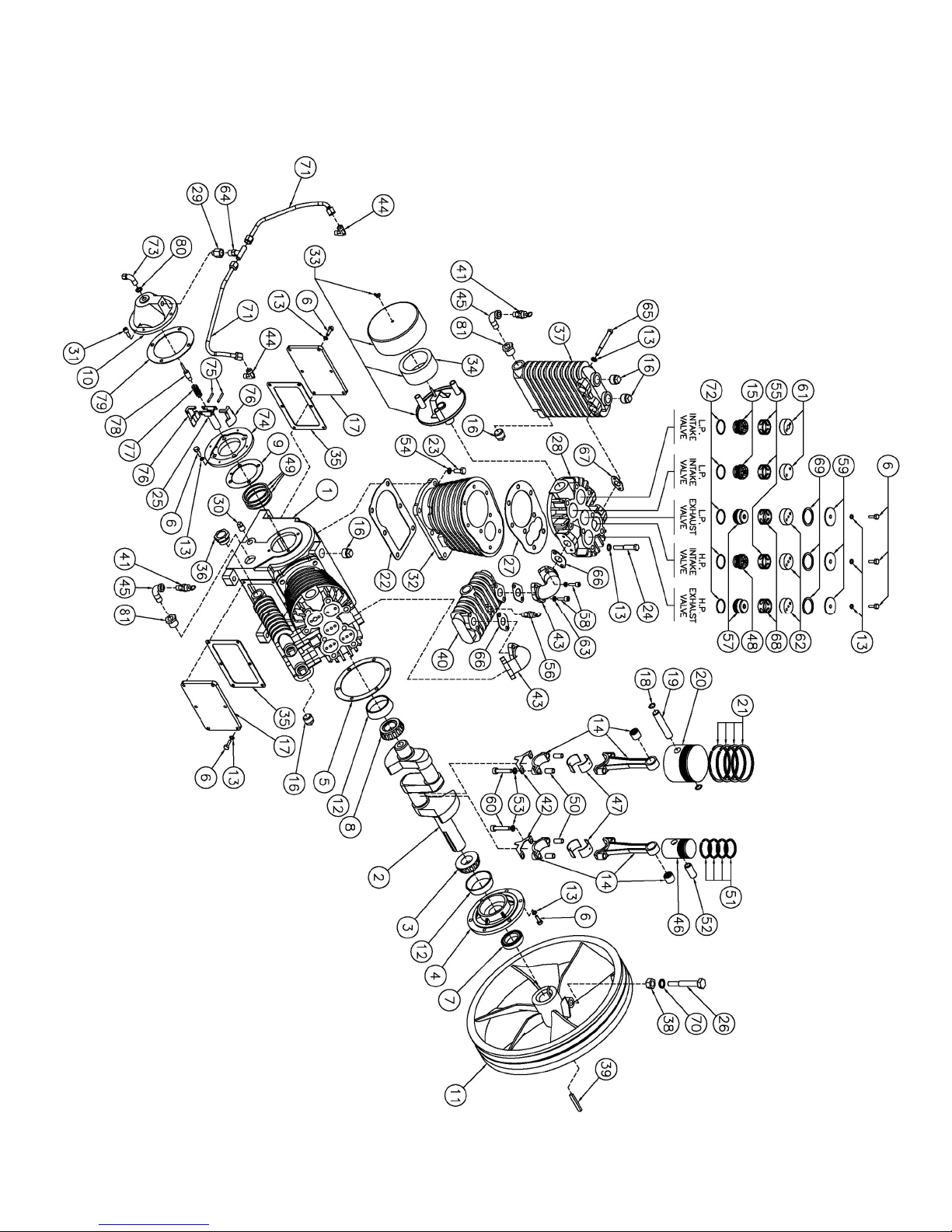
29

8. PUMP PART LISTS
10001977 – LPW6548ALHI
PUMP
USED ON ITEM 8355182
30

PUMP
10001977 – LPW6548ALHI
USED ON ITEM 8355182
31
PUMP
10002222 – LP205CT
USED ON ITEMS 8346645
32

PUMP
10002222 – LP205CT
USED ON ITEMS 8346645
33
PUMP
10002332 – LP210CT
USED ON ITEMS 8346652, 8347767 & 8347783
34

PUMP
10002332 – LP210CT
USED ON ITEMS 8346652, 8347767 & 8347783
35
 Loading...