

Page 1
1
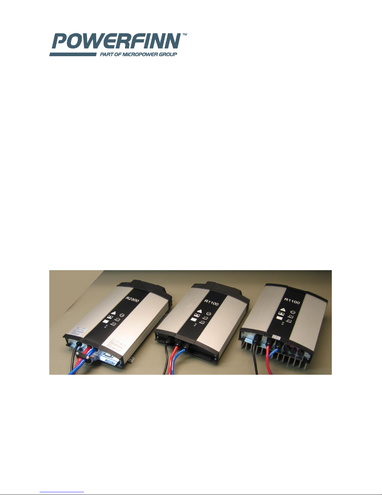
Robust series Battery Chargers
Technical handbook
11.Dec.2015
Page 2

2
Table of Contents
1 Modes ........................................................................................................................................... 3
1.1 Common features for all modes ............................................................................................ 4
2 Configurable items ........................................................................................................................ 5
2.1 Charging parameters ............................................................................................................. 5
2.2 Parallel control ....................................................................................................................... 6
2.3 Series operation ..................................................................................................................... 6
2.4 IdcLimit .................................................................................................................................. 6
2.5 UdcLimit ................................................................................................................................. 7
2.6 Remote input ......................................................................................................................... 7
2.7 Remote output ...................................................................................................................... 7
2.8 Buttons F1 and F2 .................................................................................................................. 7
2.9 CAN node-ID .......................................................................................................................... 7
3 Editing charging configuration ...................................................................................................... 8
4 Algorithms ................................................................................................................................... 11
4.1 LK10-06 freely ventilated lead-acid ..................................................................................... 11
4.2 LK10-04 freely ventilated lead-acid, using ionic mixing ...................................................... 12
4.3 LK20-09 sealed gel lead-acid.............................................................................................. 13
4.4 LK10-05 freely ventilated lead-acid, with constant voltage maintenance charging ........... 14
4.5 PP100 freely ventilated lead-acid, with constant voltage maintenance charging ............. 15
4.6 PP101 sealed gel lead-acid, with constant voltage maintenance charging ......................... 16
4.7 PP102 sealed gel lead-acid "Sonnenschein" ....................................................................... 17
5 CAN remote control .................................................................................................................... 18
5.1 Node-ID ............................................................................................................................... 18
5.2 Bit rate ................................................................................................................................. 19
5.3 Setting mode via CAN .......................................................................................................... 19
5.4 SW version ........................................................................................................................... 20
5.5 Charger mode ...................................................................................................................... 21
5.6 PDO power supply mode ..................................................................................................... 22
5.7 SDO power supply mode ..................................................................................................... 24
5.8 Powerfinn power supply mode ........................................................................................... 25
5.9 Unidirectional power supply mode ..................................................................................... 28
6 Connections ................................................................................................................................ 29
7 Options and accessories ............................................................................................................. 31
7.1 Radio module ...................................................................................................................... 31
7.2 Option cable with all wires connected ................................................................................ 31
7.3 Battery temperature sensor and voltage sense .................................................................. 32
7.4 CAN cable ............................................................................................................................ 32
8 Dimensions ................................................................................................................................. 33
Page 3

3
Introduction
For hardware specification, see separate document "Specification".
For installation and operation instructions, see "Installation and user manual".
This document presents remaining features of Robust series chargers; configuration, CAN remote
control, connections and options.
This document applies to software version 5 and later if not otherwise stated.
Information is subject to change without notice.
1 Modes
Charger has several operation modes; for example charger, SDO power supply and several
remote controlled power supply modes.
Charger mode is standalone device, which controls battery charging process according to
selected internal algorithm and other charging parameters.
PDO power supply mode is remote controlled power supply that provides setting and
measurement messages. It is necessary to keep sending messages. If required CAN messages are
not received, power output is switched off after some seconds. Note the involved SW control
loop behaviour. Constant voltage type load, for example battery, is needed for output to be
stable. SW loop has slow response to load changes. Thus, this mode might be better described as
CAN controlled battery charger.
SDO power supply mode is standalone power supply with configurable nonvolatile voltage and
current settings. In this mode, charger outputs power immediately after startup. Configuration
items UdcLimit and IdcLimit are used. This mode uses fast HW control loop, which is stable for
almost all loads.
Powerfinn power supply mode is remote controlled power supply that provides close
compatibility to Powerfinn PAP3200/CAN product family. This mode uses fast HW control loop,
which is stable for almost all loads. This feature is available in software version 7 or later.
Unidirectional power supply mode replaces PDO power supply mode in special software type
11613011. It is a simple remote controlled power supply that provides voltage and current
settings and enables compatibility to some other brands of chargers. Note the involved SW
control loop behaviour. Constant voltage type load, for example battery, is needed for output to
be stable.
Some modes can be set using the front panel. All modes can be set using CAN bus and as factory
setting. For setting modes using front panel, see chapter "Editing charging configuration" . For
setting mode using CAN bus, see chapter "Setting mode via CAN".
Page 4

4
1.1 Common features for all modes
Powerfinn Robust series chargers feature dynamic power limit. This means, maximum voltage
and maximum current can be set at same time. One of them can be output at one time.
Depending on load, output operates on voltage, current or power limit. Limits are either
maximums of the model or smaller values set by a charging algorithm, remote control messages
or configured limits.
STOP button switches output off both in charger and power supply modes. Pressing STOP again
restores output.
Remote input can be configured to start/stop functionality. Power output is on, if remote input is
active (closed contact).
Page 5

5
2 Configurable items
Some settings can be configured using front panel and CAN commands. Almost all settings can be
configured using optional radio module. All settings can be set at the factory.
configuring method
documented in
front panel
chapter "Editing charging configuration"
CAN bus
chapter "CAN remote control"
radio
Micropower Access Service Tool documentation
factory setting
ask from your supplier. Convenient if your order large quantities.
Operation modes are described in chapter "Modes". Other items are listed below.
2.1 Charging parameters
This group of settings includes algorithm, battery capacity, cellcount, cable resistance and base
load. These items are applied only in charger mode. These settings can be set also using CAN bus.
See chapter "CAN remote control".
Algorithm number
configurable via
front panel: yes
CAN: yes
radio: yes
factory setting: yes
Default value: 1
Algorithm number is unique identifier of algorithms within Micropower Access and
Powerfinn Robust series of chargers. See chapter "Algorithms" for available algorithms and
numbers.
Battery capacity
configurable via
front panel: yes
CAN: yes
radio: yes
factory setting: yes
Default value: 50, unit: Ah, range: 50 ... 2000
A list of predefined values between 50 and 800 is available using the front panel. See
chapter "Editing charging configuration". While these are often sufficient, battery capacity
can be set freely using other methods. Accurate capacity setting ensures optimal charging
process.
Number of cells
configurable via
front panel: no
CAN: yes
radio: yes
factory setting: yes
Default value: (according to nominal voltage of the model), unit:-, range: 6 ... 50 ( naturally
meaningful maximum depends on nominal voltage of the model).
Number of cells can be configured to a lower value than the nominal. For example 12 V
battery can be charged using nominally 24 V charger.
Base load
Page 6

6
configurable via
front panel: no
CAN: yes
radio: yes
factory setting: yes
Default value: 0, unit:mA , range: 0 ... 65535
Eventual current consumption of a load parallel to battery during charging can be
compensated with this parameter.
Cable resistance
configurable via
front panel: no
CAN: yes
radio: yes
factory setting: yes
Default value: 0, unit: mOhm, range: 0 ... 99
Voltage drop in cabling between charger and battery can be compensated with this
parameter. Depending on algorithm, this can improve charging process efficiency. Be
careful not to overcompensate as this can result in unstable operation and too high cell
voltages.
2.2 Parallel control
configurable via
front panel: yes
CAN: no
radio: yes
factory setting: yes
Default value: off, range: off/on
This setting enables group of chargers, connected in parallel, to deliver large current.
When value "on" is selected, this charger controls other Robust series chargers over CAN
bus. Other chargers in group should be configured with default values (charger mode,
parallel control off).
Software version 6 or later is required for this feature.
This kind of parallel operation is possible in charger and PDO power supply modes.
In charger mode, the master charger (with parallel setting on) controls the other chargers.
Up to five chargers can be connected. Eventual optional connections should be made to
the master charger.
In PDO power supply mode, the master charger appears as one charger to CAN system
controller.
2.3 Series operation
Series operation for large output voltage is not supported by Robust software. Connecting
Robust chargers in series is not recommended.
2.4 IdcLimit
configurable via
front panel: no
CAN: yes
radio: yes
factory setting: yes
Default value: max. current of the model, unit: A, range: 0...max. current of the model
Parameter IdcLimit defines maximum DC current output. In case of other DC current
limits, for example that calculated by charging algorithm or CAN messages in PDO power
supply mode, lowest limit defines maximum current output. IdcLimit is not applied in
Powerfinn power supply mode. IdcLimit is also the current setting in SDO power supply
mode. See chapter "CAN remote control" - "SDO power supply mode" for CAN messages.
Page 7

7
2.5 UdcLimit
configurable via
front panel: no
CAN: yes
radio: yes
factory setting: yes
Default value: nominal voltage of the model, unit: mV, range: 0...max. voltage of the model
UdcLimit is is the voltage setting in SDO power supply mode.
See chapter "CAN remote control" -" SDO power supply mode" for CAN messages.
2.6 Remote input
configurable via
front panel: yes
CAN: no
radio: yes
factory setting: yes
Default value: no function, range: no function, start/stop, stop
When value "start/stop" is configured, active remote input is required for power output.
Value "stop" is not documented yet.
This setting is valid in all modes.
Using front panel, values "no function" and "start/stop" can be selected.
Physical connection is documented in chapter "Connections".
2.7 Remote output
configurable via
front panel: no
CAN: no
radio: yes
factory setting: yes
Default value: "no function" in SW v6 and earlier, "mains" in SW v7 and later, range: no
function, alarm, phase, BBC, water, air pump, mains
When value "alarm" is configured, remote output relay is activated during all alarms.
When value "mains" is configured, remote output relay is activated whenever charger is
mains powered.
This setting is valid in all modes.
Physical connection is documented in chapter "Connections".
Remote output can be connected also to button F1 or F2. Button connection overrides
other functions using the remote output.
Remote output has some additional configuration possibilities. For description of these,
see MP Access documentation.
2.8 Buttons F1 and F2
configurable via
front panel: no
CAN: no
radio: yes
factory setting: yes
Default value: no function, range: no function, equalize, remote out
When value "equalize" is configured, the button will trigger equalize charging. This
function tells the charging curve to run an equalize charge. How the actual equalize charge
is performed is defined in the charging curve, normally when the battery is fully charged.
The button can be pressed at any time even if no battery is connected.
When value "remote out" is configured, the button will toggle the remote output relay.
Button connection overrides other functions using the remote output.
2.9 CAN node-ID
configurable via
front panel: no
CAN: yes
radio: yes
factory setting: yes
Default value: 1 in SW version 6 and earlier, 1Dh in SW version 7, range: 1 ... 127
This setting is applied in power supply modes. CAN node-IDs are automatically set in
charger mode. See chapter "CAN remote control" for CAN messages.
Page 8

8
3 Editing charging configuration
This chapter presents editing charging configuration using the front panel. Also CAN-bus and
optional radio module can be used, see separate chapters.
1. Disconnect battery.
2. Connect mains power.
3. Wait until blue LED lits. Within 20 s, press STOP, and keep pressing for 10 s. LED's should flash
shortly. Release STOP. Special configuration mode has been entered.
4. Press STOP to scroll down the list. List of items are in table below.
5. To set item on/off, press F1.
6. After you have selected algorithm and battery capacity (and eventual other selections),
disconnect mains power. Configuration is automatically stored to non-volatile memory.
Following table applies to program version 2 and later. Bold text in coloured areas indicates LED
“on”.
Page 9

9
item
1
red
yellow
green
blue
s.green
algorithm 1 LK10-06 freely ventilated lead-acid (default)
2
red
yellow
blue
s.green
algorithm 2 LK10-04 freely ventilated lead-acid
3
red green
blue
s.green
algorithm 3 LK20-09 sealed gel lead-acid
4
red
blue
s.green
algorithm 16 LK10-05 freely ventilated lead-acid
5 blue
s.green
algorithm 17 PP100 freely ventilated lead-acid, with constant
6
green
blue
s.green
algorithm 18 PP101 sealed gel lead-acid
7 yellow
blue
s.green
algorithm 19 PP102 sealed gel lead-acid "Sonnenschein"
8 yellow
green
blue
s.green
algorithm --
9
red
yellow
green
s.green
capacity 50 Ah (default)
10
red
yellow
s.green
capacity 75 Ah
11
red green
s.green
capacity 100 Ah
12
red s.green
capacity 125 Ah
13
s.green
capacity 150 Ah
14
green
s.green
capacity 200 Ah
15 yellow
s.green
capacity 250 Ah
16 yellow
green
s.green
capacity 300 Ah
17
red
yellow
green
blue capacity 350 Ah
18
red
yellow
blue capacity 400 Ah
19
red green
blue capacity 450 Ah
20
red
blue capacity 500 Ah
21 blue capacity 550 Ah
22
green
blue capacity 600 Ah
23 yellow
blue capacity 700 Ah
24 yellow
green
blue capacity 800 Ah
25
red
yellow
green
Charging mode
26
red
yellow
Remote input, off-no function, on-start/stop
27
red green
CAN function
28
red
Parallel control
29 Battery monitoring unit control
Page 10
10
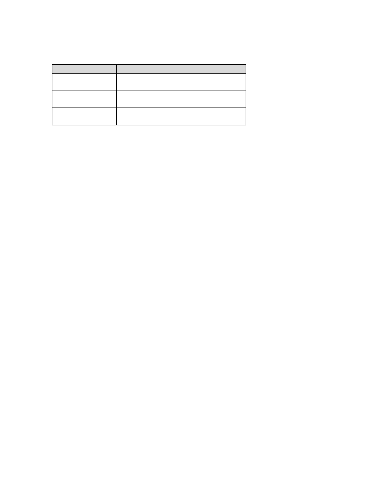
Description of some configurable items
Charging mode and CAN function
Modes are set using two configurable items
mode
set item
Charger (default)
25, Charging mode: off
27, CAN function: off
PDO power supply
25, Charging mode: off
27, CAN function: on
SDO power supply
25, Charging mode: on
27, CAN function: on
Other modes are not accessible via front panel.
Remote input
Default value is "no function". When value "Start/Stop" is selected, active remote input is required
for power output.
Battery monitoring unit control
Default setting is off. When optional radio module and battery monitoring unit are installed,
charging process can be controlled by the battery monitoring unit. For more information, see
Micropower Access documentation.
Page 11
11
4 Algorithms
Verify compatibility of the algorithm with the battery manufacturer.
Notes
- "sealed" is a generic term for GEL and AGM types of lead-acid batteries, which are not freely
ventilating to surrounding air.
- Current is indicated in terms of C, which is current compared to nominal capacity. For example 0.2
C for 100 Ah battery is 20 A.
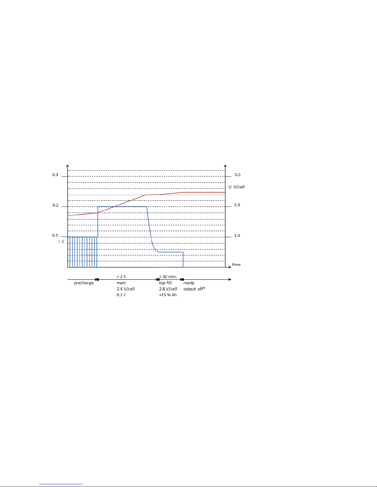
4.1 LK10-06 freely ventilated lead-acid
Algorithm number: 1
Charging phase "top fill" charges +15 % compared to charged Ah of main phase.
Battery temperature compensation:
- voltage -3 mV / °C per cell, neutral at 30 °C
- current derated to zero in the range [-30 ... -35] and [+45 ... +60] °C
* In maintenance phase, battery voltage is periodically checked. If it is below 2.17 V/cell, 2 minute
0.05 C current pulse is used.
Page 12
12
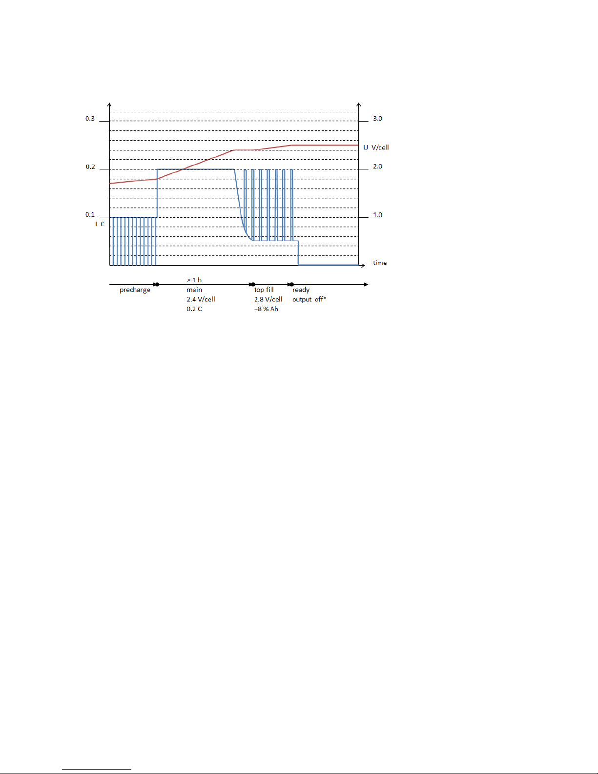
4.2 LK10-04 freely ventilated lead-acid, using ionic mixing
Algorithm number: 2
Ionic mixing current pulses are used to reduce charging time without using air pump.
Charging phase "top fill" charges +8 % compared to charged Ah of main phase.
Battery temperature compensation:
- voltage -3 mV / °C per cell, neutral at 30 °C
- current derated to zero in the range [-30 ... -35] and [+45 ... +60] °C
* In maintenance phase, battery voltage is periodically checked. If it is below 2.17 V/cell, 2 minute
0.05 C current pulse is used.
Page 13
13
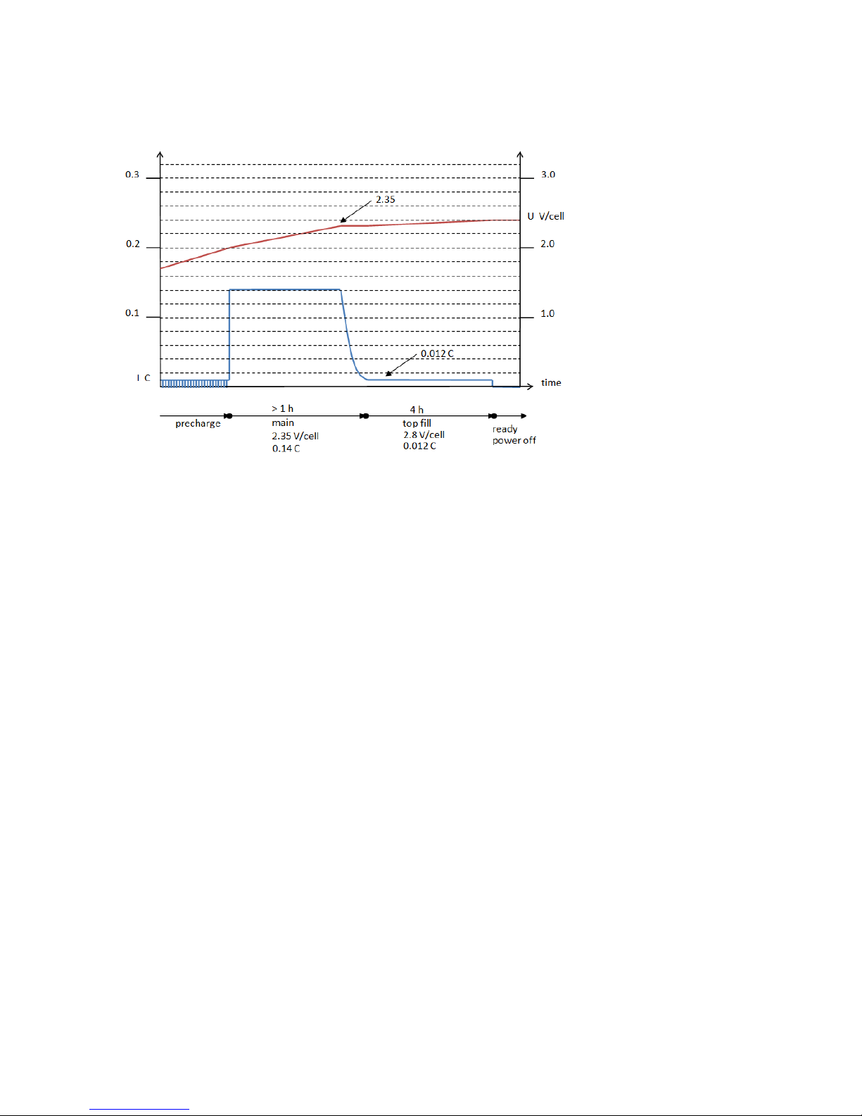
4.3 LK20-09 sealed gel lead-acid
Algorithm number: 3
Battery temperature compensation: none.
This algorithmhas equalization built-in. If battery is left connected to charger for 16 hours, a 30 h
equalization phase runs with current 0.006 C and voltage 2.8 V/cell. This could be useful to
perform equalizing over a weekend.
Page 14
14
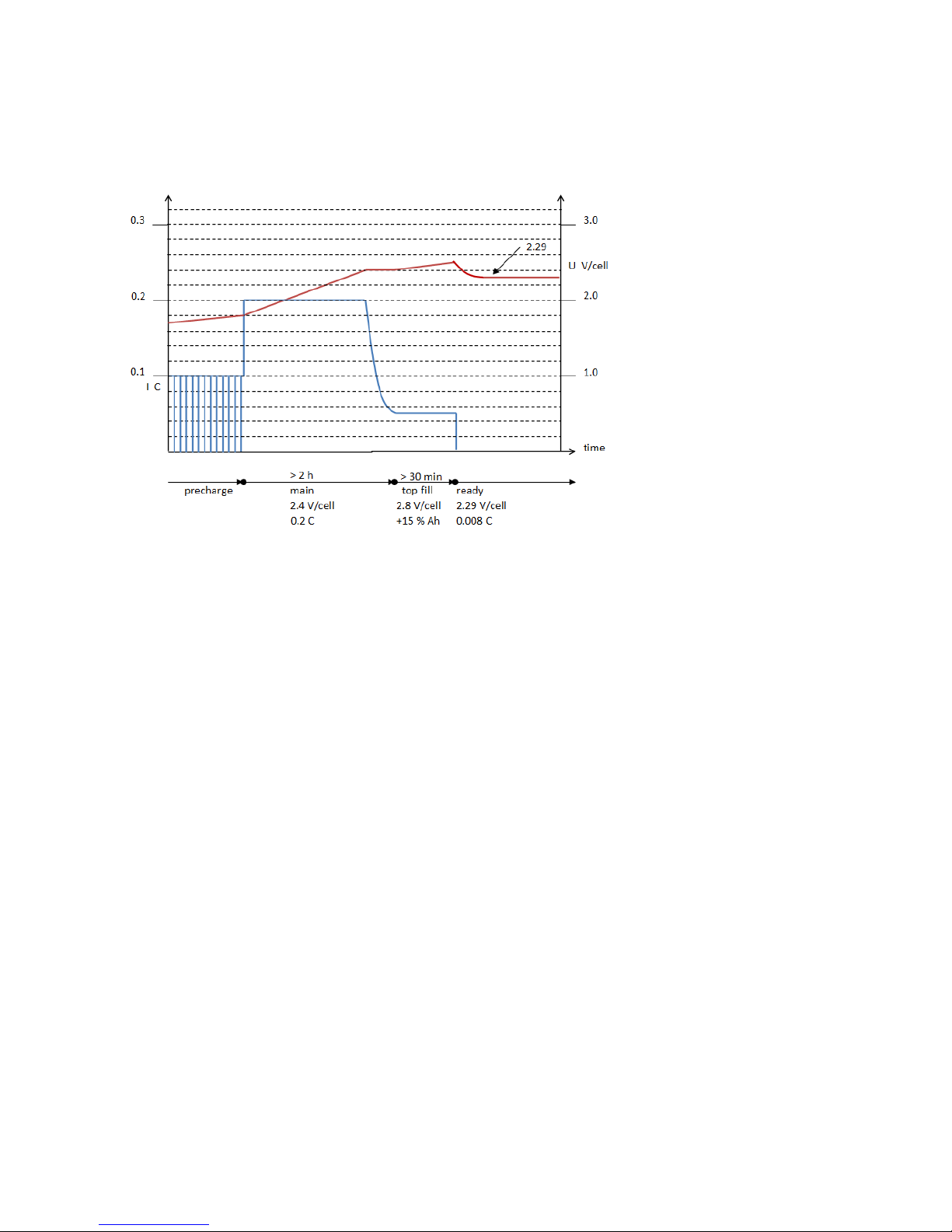
4.4 LK10-05 freely ventilated lead-acid, with constant voltage
maintenance charging
Algorithm number: 16
Charging phase "top fill" charges +15 % compared to charged Ah of main phase.
Battery temperature compensation:
- voltage -3 mV / °C per cell, neutral at 30 °C
- current derated to zero in the range [-30 ... -35] and [+45 ... +60] °C
Page 15
15
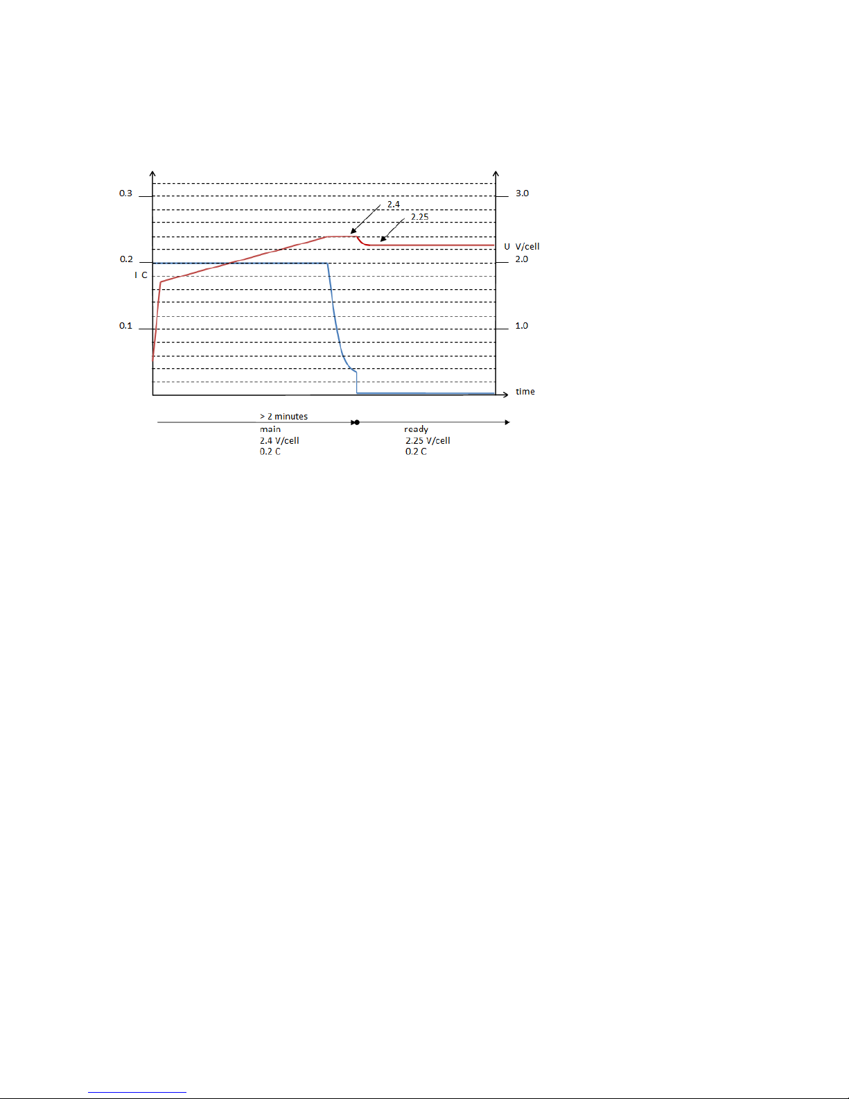
4.5 PP100 freely ventilated lead-acid, with constant voltage
maintenance charging
Algorithm number: 17
Battery temperature compensation:
- voltage -4 mV / °C per cell, neutral at 25 °C
- current derated to zero in the range [-30 ... -35] and [+40 ... +50] °C
Note, this algorithm uses low battery detection voltage: 0.5 V/cell. Be careful not to inadvertently
use battery with smaller number of cells, for example 24 V charger for a 12 V battery.
Page 16
16
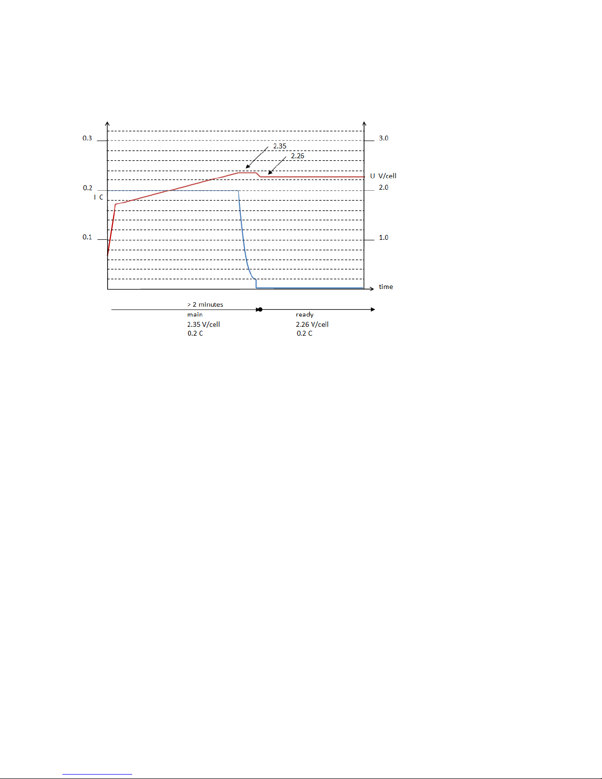
4.6 PP101 sealed gel lead-acid, with constant voltage
maintenance charging
Algorithm number: 18
Battery temperature compensation:
- voltage -4 mV / °C per cell, neutral at 25 °C
- current derated to zero in the range [-30 ... -35] and [+40 ... +50] °C
Note, this algorithm uses low battery detection voltage: 0.5 V/cell. Be careful not to inadvertently
use battery with smaller number of cells, for example 24 V charger for a 12 V battery.
Page 17
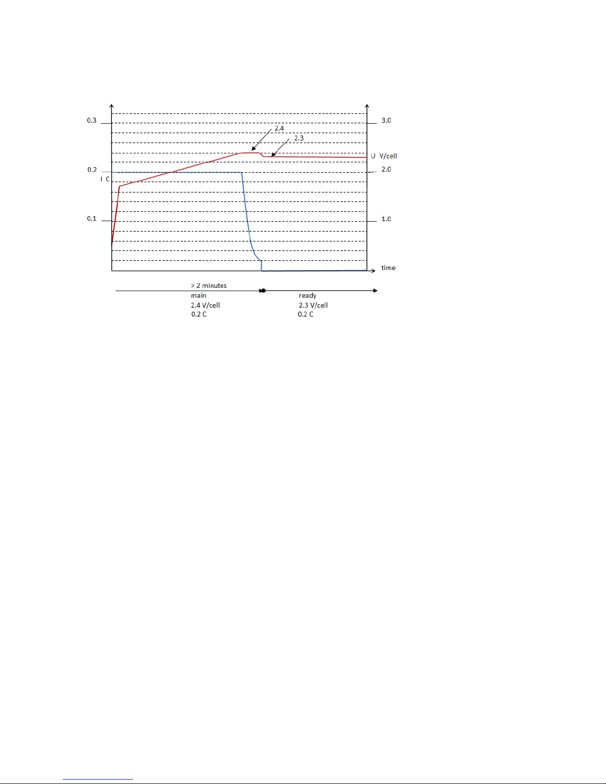
17
4.7 PP102 sealed gel lead-acid "Sonnenschein"
Algorithm number: 19
Battery temperature compensation:
- voltage -4 mV / °C per cell, neutral at 25 °C
- current derated to zero in the range [-30 ... -35] and [+40 ... +50] °C
Note, this algorithm uses low battery detection voltage: 0.5 V/cell. Be careful not to inadvertently
use battery with smaller number of cells, for example 24 V charger for a 12 V battery.
Page 18
18
5 CAN remote control
For physical connection to CAN port, see chapter "Connections".
Robust series CAN communication is not CiA certified nor CANopen complete but communication
is based on CANopen. In the following presentation, basic knowledge about CAN and CANopen is
assumed.
Frame: Standard CAN frame with 11-bit identifier
Bit rate: 20 ... 1000 kbit/s
Node-ID: 1 ... 127
Configurable items are accessed using CANopen SDO protocol. See "Node-ID" for examples of how
CAN messages are built.
Nonvolatile settings are nonvolatile without separate save command, automatically written to
flash. Therefore, for long lifetime, avoid sending excessive amounts of these messages.
Most nonvolatile settings are active immediately but some require restart.
5.1 Node-ID
This CANopen object is used to configure node-ID
index
subindex
format
unit
range
default
value
item
2057h
01
uint8
1...127
1Dh*
CAN node-ID
*Default node-ID is 1 in software version 6 and earlier.
Changed CAN node-ID is nonvolatile, active immediately after response.
Node-ID is automatically assigned in charger mode, so configured node-ID is ignored.
Message to access node-ID is built according to CANopen SDO protocol:
CAN-ID: 600h + node-ID, DLC: 8, data[0]: according to CANopen, data[1-2]: OD index, data[3]: OD
subindex, data[4]: node-ID. Unused bytes are ignored.
Example messages
CAN-ID
DLC
data [0...7] (hex)
comment
601h
8
40 57 20 01 00 00 00 00
read CAN node-ID
581h
8
4F 57 20 01 01 00 00 00
response from charger: node-ID is 1
CAN-ID
DLC
data [0...7] (hex)
comment
601h
8
2F 57 20 01 02 00 00 00
write CAN node-ID 2
581h
8
60 57 20 01 01 00 00 00
response from charger
Page 19
19
Note, the first data byte in SDO write operation is 2Fh for 1-byte object, 2Bh for 2-byte object and
23h for 4-byte object. For 4-byte object, also 22h can be used. Unused data in response might be
filled with random data.
Note, CANopen uses little endian byte order.
5.2 Bit rate
This CANopen object is used to configure bit rate
index
subindex
format
unit
range
default
value
item
5FFFh
02
uint16
kbit/s
20...1000*
125
CAN bit rate
*values 20, 50, 125, 250, 500, 800 and 1000 are supported
Changed bit rate is nonvolatile, active after restart.
This feature is available in software version 7 and later.
5.3 Setting mode via CAN
Mode is defined by two CANopen objects
index
subindex
format
unit
range
default
value
item
2058h
01
uint8
0...3
0
ChargingMode
2056h
01
uint8
0...3
1
CAN function
For a mode, set these two objects to
mode
ChargingMode
CAN function
charger
0
1
PDO power supply
0
3
SDO power supply
2 3 Powerfinn power supply
3
3
Other combinations of values are reserved.
These settings are nonvolatile. Some mode changes are active immediately, some require restart.
This feature is available in software version 7 and later.
Page 20
20
5.4 SW version
Charger SW version can be read using SDO objects
index
subindex
format
unit
range
default
value
item
2202h
01
uint32
SW type; 11613002 for standard SW.
Does not change for the lifetime of the
SW.
2202h
02
uint32
SW version, incremented for new
versions.
This feature is available in software version 7 and later.
Page 21
21
5.5 Charger mode
At startup, charger sends boot-up message
CAN-ID: 700h + node-ID, DLC: 1, data: 0
Charger sends heartbeat message once per second
CAN-ID: 700h + node-ID, DLC: 1, data: 05h
Charger sends SYNC message once per second
CAN-ID: 080h, DLC: 0
Charger enters operational state automatically. Charger sends some other CAN messages related
to automatic group functionality.
Charging parameters
These CANopen SDO objects are used to configure charging parameters.
index
subindex
format
unit
range
default
value
item
2000h
01
uint16
1
algorithm number
2000h
02
uint16
Ah
50...2000
50
battery capacity
2000h
03
uint16
6...50
12*
number of cells
2000h
04
uint16
mA
0...65535
0
base load
2000h
05
uint16
mOhm
0...99
0
cable resistance
* number of cells is set at the factory according to nominal voltage; 12 cells for 24 V model, 18 for
36 V model, 24 for 48 V model.
These settings are nonvolatile.
Measurements or monitoring
In software version 7 and later, measurements are available via Powerfinn power supply mode
messages, which work also in charger mode. See chapter "Powerfinn power supply mode"
Page 22
22
5.6 PDO power supply mode
This power supply mode uses CANopen PDO protocol.
After startup, charger is in pre-operational state.
Charger sends boot-up message
CAN-ID: 700h + node-ID, DLC: 1, data: 0.
Charger sends heartbeat message once per second
CAN-ID: 700h + node-ID, DLC: 1, data: 7Fh.
Set charger to operational state by sending start remote node message
CAN-ID: 000, DLC: 2, data[0]: 1, data[1]: node-ID
for example
CAN-ID
DLC
data (hex)
comment
000h
2
01 01
start device with node-ID 01
Then, charger sends heartbeat message once per second
CAN-ID: 700h + node-ID, DLC: 1, data: 05h.
Note, charger sends some extra messages during startup and change of operational state.
Power output
For power output, three CANopen PDO messages are needed from CAN controller to charger.
1) Voltage and current setting
CAN-ID: 200h + node-ID, DLC: 8, data[0-3]: voltage in Volts, data[4-7]: current in Amperes.
Numeric format: IEEE-754 single precision floating point, 32 bit.
Note the little endian byte order of CANopen. Example message:
CAN-ID
DLC
data (hex)
comment
201h
8
00 00 10 42 00 00 20 42
Uset 36.0 V, Iset 40.0 A
2) Power setting
CAN-ID: 300h + node-ID, DLC: 8, data[0-3]: power in Watts, data[4-7]: not used, set to 0. Numeric
format: IEEE-754 single precision floating point, 32 bit.
Example message:
CAN-ID
DLC
data (hex)
comment
301h
8
00 80 89 44 00 00 00 00
Pset 1100 W
3) SYNC
CAN-ID
DLC
data (hex)
comment
080h
1
00
Page 23
23
Period of one second is recommended. If these messages are not received for some seconds,
power output is switched off.
Note, configuration item IdcLimit applies in PDO power supply mode.
Measurements
In operational state, sending sync produces two PDO messages of measurement data as response.
1) Voltage and current
CAN-ID: 180h + node-ID, DLC: 8, data[0-3]: voltage in Volts, data[4-7] current in Amperes.
Numeric format: IEEE-754 single precision floating point, 32 bit. For example
CAN-ID
DLC
data (hex)
comment
181h
8
B1 88 C3 41 82 01 F0 41
Umeas 24.441733 V, Imeas 30.000736 A
2) Power
CAN-ID: 280h + node-ID, DLC: 8, data[0-3]: power in Watts, data[4-7]: (reserved).
Numeric format: IEEE-754 single precision floating point, 32 bit. For example
CAN-ID
DLC
data (hex)
comment
281h
8
F4 4A 37 44 12 00 00 00
Pmeas 733.17114 W
Page 24
24
5.7 SDO power supply mode
In this mode, charger outputs power immediately after startup.
For defining power output, two CANopen SDO objects are used:
index
subindex
format
unit
range
default
value
item
2001h
01
uint32
mV
0...max*
nom**
UdcLimit
2001h
02
uint32
A
0...max*
max*
IdcLimit
* maximum output of the model
** nominal voltage of the model
Note that values are nonvolatile, automatically written to flash. Therefore, for long lifetime, avoid
sending excessive amounts of these messages.
Note, configuration item IdcLimit applies also in other operation modes. See "Configurable items"
- "IdcLimit".
Example messages
CAN-ID
DLC
data (hex)
comment
601h
8
23 01 20 01 C0 5D 00 00
U set 24000 mV
CAN-ID
DLC
data (hex)
comment
601h
8
23 01 20 02 0A 00 00 00
I set 10 A
At startup, charger CAN behaviour is similar to PDO power supply mode. Entering operational
state is not required for power output. It can be entered and measurements are available same
way as in PDO power supply mode.
Page 25
25
5.8 Powerfinn power supply mode
Powerfinn power supply mode provides close CAN remote control compatibility to Powerfinn
PAP3200/CAN product family. This mode is available in software version 7 and later.
Power output
These CANopen SDO objects are used to set power output:
index
subindex
format
unit
range
default
value
item
2401h
01
uint32
mV
0...max*
-**
Uset
2401h
02
uint32
mA
0...max*
-**
Iset
* maximum output of the model
** Default Uset and Default Iset are used as startup values, see below.
These settings are volatile.
After startup, voltage and current settings are initially zero. They can also be set to non-zero
values.
index
subindex
format
unit
range
default
value
item
2401h
06
uint32
mV
0...max*
0
Default Uset
2401h
07
uint32
mA
0...max*
0
Default Iset
* maximum output of the model
These settings are nonvolatile.
Measurements
index
subindex
format
unit
range
default
value
item
2402h
01
uint32
mV
0...max
-
Uact, measured output voltage
2402h
02
uint32
mA
0...max
-
Iact, measured output current
2402h
06
int32
0.1 °C
-50...+150 °C
-
internal temperature
CAN safety timer
If a new Uset/Iset message from CAN controller is not found within a time interval (it is assumed
that CAN control is lost), active Uset and Iset values are replaced by default Uset and default Iset
values. Setting CAN safety timer to zero means this feature is not active.
Page 26
26
index
subindex
format
unit
range
default
value
item
2401h
0Bh
uint8
s
0...255
0 (off)
CAN safety timer
This setting is nonvolatile.
Example
After startup, charger sends heartbeat once/second. The data is 7Fh, which hints that device is in
pre-operational state. Despite this, there is no need to send start node message to output power.
Minimum messages to output power in Powerfinn power supply mode are Uset and Iset. Here is a
CAN bus log from startup to power output:
#
time s
ID
DLC
data
notes
1
2.208
Tx
071D
1
00
bootup message
2
2.210
Tx
009D
8
00 00 00 00 00 00 00 00
3
3.207
Tx
071D
1
7F
heartbeat
4
4.207
Tx
071D
1
7F 5
4.984
Rx
061D
8
22 01 24 01 10 27 00 00
Uset 10 000 mV
6
4.987
Tx
059D
8
60 01 24 01 00 00 00 00
response
7
5.207
Tx
071D
1
7F 8
6.206
Tx
071D
1
7F 9
6.596
Rx
061D
8
22 01 24 02 88 13 00 00
Iset 5000 mA
10
6.599
Tx
059D
8
60 01 24 02 00 00 00 00
response
11
7.206
Tx
071D
1
7F 12
8.205
Tx
071D
1
7F 13
9.205
Tx
071D
1
7F
Differences between Robust series Powerfinn power supply mode and
PAP3200/CAN power supply mode
SDO download message
First byte "nes" bits (see CiA 301 7.2.4.3.3) need careful setting in Robust series. PAP3200
accepts any alternative for first byte, even a non-correct one. For Robust, they must indicate
correct data length, except also 22h as first byte is accepted for four bytes data length.
LED indication
PAP3200/CAN has yellow constantly on. Robust sets big yellow on when power output is on.
High internal temperature
PAP3200/CAN shows red color in its sole LED, Robust shows steady red and blinking yellow. The
temperature limits for showing alarm and switching output off, vary somewhat between
models. Operating charger within environmental specification ensures internal temperature
low enough.
Periodic CAN messages
PAP3200/CAN does not send heartbeat. Robust sends heartbeat CAN-ID:700h + node-ID, DLC:
Page 27
27
1, data:7Fh, once per second.
Event related CAN messages
Robust sends some extra messages, for example at startup CAN-ID 800h + node-ID, DLC: 8, data
00 00 00 00 00 00 00 00.
Bootup CAN messages
PAP3200/CAN sends two bootup messages, Robust one. For example
CAN-ID
DLC
data
CAN-ID
DLC
data
PAP3200
71Dh
1
01
71Dh
1
00
Robust
71Dh
1
00
The first bootup message from PAP3200/CAN uses fixed node-ID of 1Dh and fixed bit rate 125
kbit/s. The second bootup message uses configured node-ID and bitrate.
CAN safety timer
PAP3200/CAN safety timer can be kept inactive with any message with correct node-ID. Robust
requires Uset or Iset message.
CAN node-ID
PAP3200/CAN node-ID is accessed using OD index 5FFFh. Robust node-ID can be accessed
same way in SW version 7 and later. OD index 2057h works in all Robust SW versions.
Changed node-ID is active after restart in PAP3200/CAN, immediately (after response) in
Robust.
Page 28
28
5.9 Unidirectional power supply mode
Unidirectional power supply mode replaces PDO power supply mode in SW type 11613011. It
allows Powerfinn Robust series chargers to partially emulate some other brands of chargers. The
term unidirectional derives from the fact that in this mode CAN controller sends messages to
charger but charger does not send messages to CAN controller. Charger does send heartbeat
message
CAN-ID: 700h + node-ID, DLC: 1, data: 5, once per second.
Power, voltage and current are set using one message.
CAN-ID: 400h + node-ID, DLC: 8,
data[0]: power on/off, use value 1 for power on, 0 for power off,
data[1-2], power limit in 0.1 % *
data[3-4], voltage in 0.1 Volts,
data[5-6]: current in 0.1 Amperes,
data[7]: (not used)
Numeric format: 16 bit unsigned int.
* Value of 100 % is recommended.
Note the little endian byte order of CANopen. Example message:
CAN-ID
DLC
data (hex)
comment
401h
8
01 E8 03 F4 01 64 00 00
Power on, P=100%, 50.0 V, 10.0 A
Period of one second is recommended. If this message is not received for some seconds, power
output is switched off.
Page 29
29
6 Connections
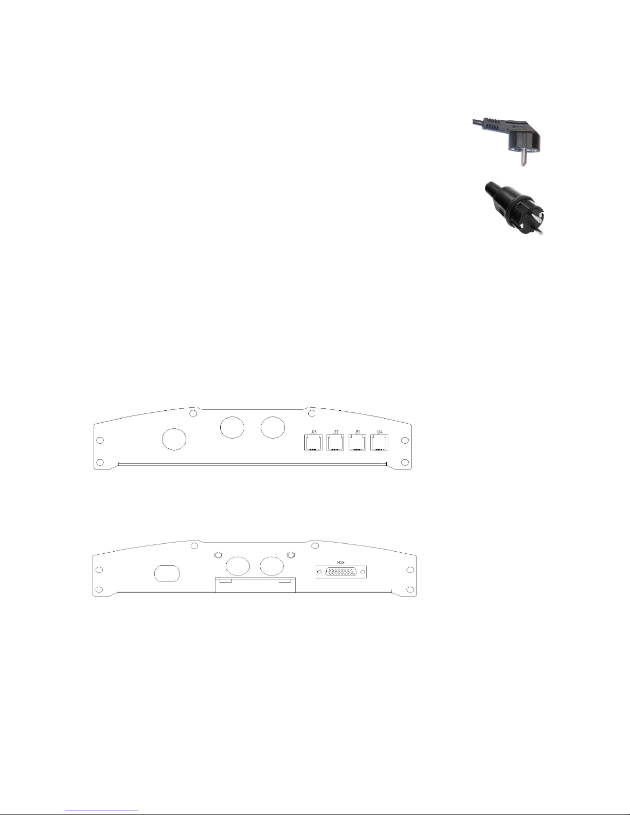
Mains cable of Robust 1100 is as standard 1.5 m of length, terminated to
european style schuko plug.
Mains cable of Robust 2300 is as standard 2.5 m of length, terminated to european
style schuko plug.
DC cables of Robust 1100 chargers are as standard 2*10 mm2, 2 m length, not terminated.
DC cables of Robust 2300 chargers are as standard 2*25 mm2, 2 m length, not terminated.
Ask your supplier for alternatives.
Robust 1100 chargers provide optional features over 4 pcs of RJ11 sockets located in the bottom
side. There are some limitations on connecting these. Not all can be connected at the same time
while maintaining IP class. For details, ask your supplier or the manufacturer.
Robust 2300 and 3000 chargers provide optional features over a 26-pin high-density D-sub socket
located in the bottom side.
Page 30
30
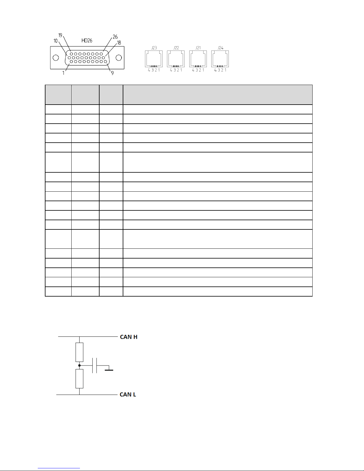
RJ
pin
RJ wire
color
HD26
pin
Description
J23-1
black
4
LED green anode (10mA current source)
J23-2
red
22
LED common cathode (connected to battery minus)
J23-3
green
14
LED red anode (10mA current source)
J23-4
yellow
5
LED yellow anode (10mA current source)
J22-1
black
2
Sense plus (+)
J22-2
red
12
Battery temperature compensation (-) (Sensor consists of two
Philips KTY83-120 sensors connected in series)
J22-3
green
3
Battery temperature compensation (+)
J22-4
yellow
20
Sense minus (-)
J21-1
black
19
Remote input (+) *
J21-2
red
1
CAN-bus Hi *
J21-3
green
10
CAN-bus Lo *
J21-4
yellow
11
Remote input (-) *
J24-1
black
26
Remote output relay, Common (0.5A@125Vac, 2A@30VDC,
0.3A@110VDC)
J24-2
red
18
Remote output relay, Normally Open
J24-3
green
9
Remote output relay, Normally Closed
J24-4
yellow
Not connected
25
Isolated +5V, 50 mA output *
7
Isolated output ground * (same ground as in HD26 pin 11)
* Note: CAN bus signals, remote input and isolated 5 V output operate from supply, which is
galvanically isolated from charger DC output.
CAN bus is using internally weak split termination (2 * 1 kOhm, 100 nF).
For available cables to utilize these optional features, see chapter "Options and accessories".
Page 31
31
7 Options and accessories
Options and accessories in addition to those listed here might be available. Ask your supplier.
7.1 Radio module
Robust series chargers can be equipped at the factory with optional internal radio module. Radio
module enables short range communication with other chargers and battery monitoring units. Also
communication to PC-computer via USB radio dongle is possible. The radio functionality of
Powerfinn Robust series and Micropower Access series is compatible.
Microsoft Windows™ software "MP Access Service Tool" is convenient tool for
- configuring chargers and the system
- reading logs and statistical data from charger
- monitoring charger operation in real time
For more information on using the radio functionality, see MP Access documentation.
7.2 Option cable with all wires connected
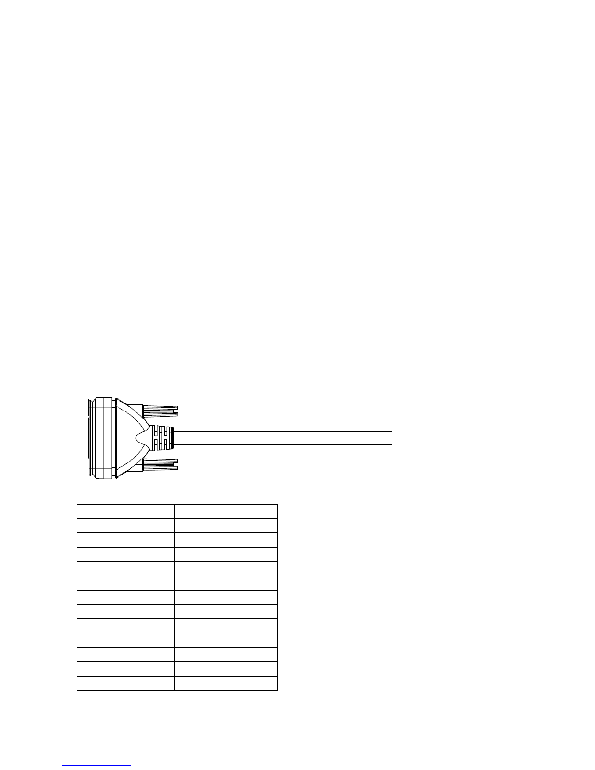
Molded package with integrated 2 m cable, IP67, wires appr. AWG26 / 0.13 mm2, unterminated
pin numbers and wire colors
01 brown
14 brown/white
02 blue
15 red/white
03 white
16 orange/white
04 green
17 green/white
05 yellow
18 blue/white
06 gray
19 purple/white
07 pink
20 red/black
08 red
21 orange/black
09 black
22 yellow/black
10 orange
23 green/black
11 purple
24 gray/black
12 light green
25 pink/black
13 black/white
26 pink/red
Page 32
32
7.3 Battery temperature sensor and voltage sense
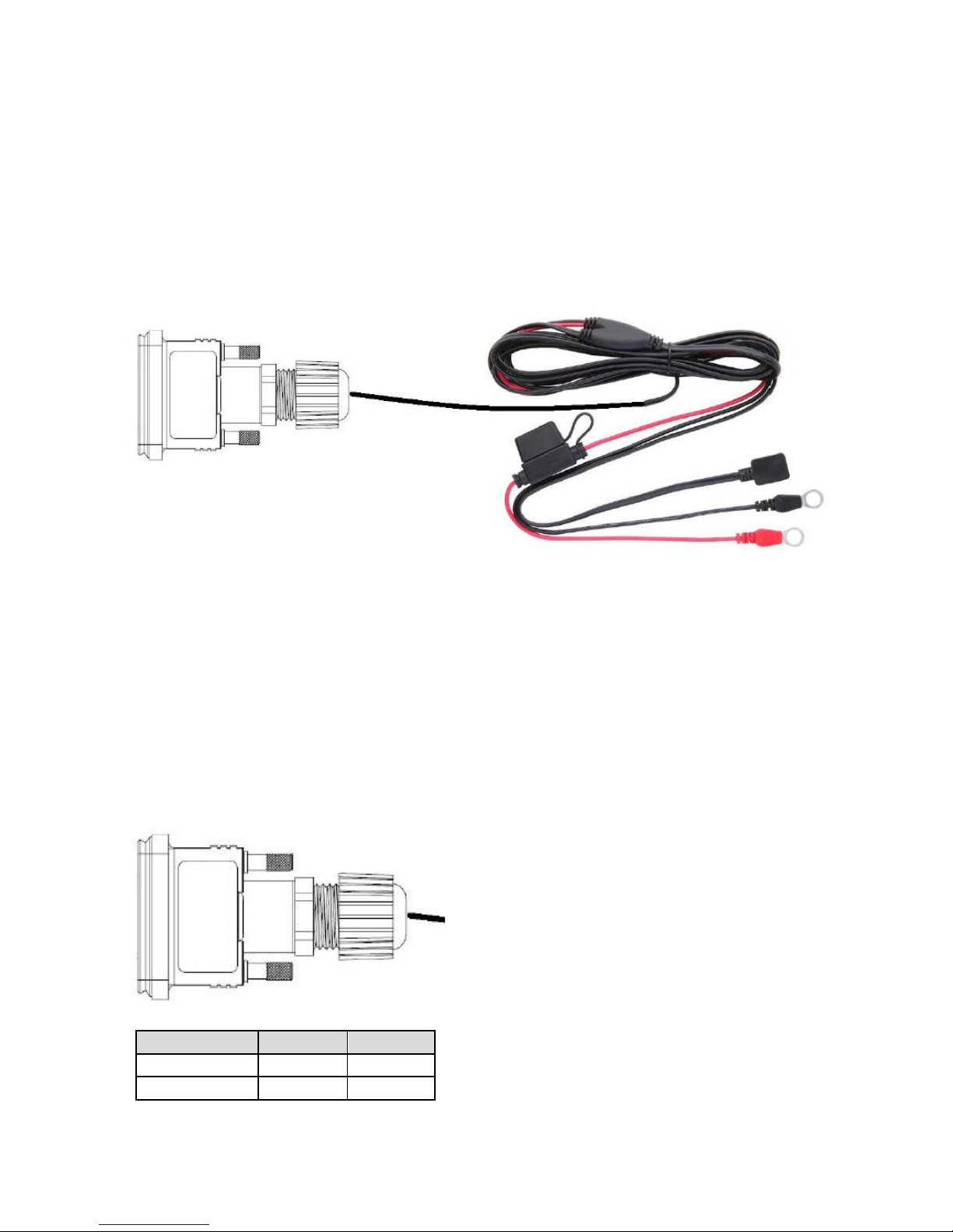
In charger mode, battery temperature compensation is automatically used, if sensor is connected
and selected algorithm has temperature compensation defined.
In charger mode, DC cable voltage loss compensation can be done programmatically using
charging parameter "cable resistance". Compensation can also be done by hardware using sense
wires. This method works in all modes.
Length 2.5m to first joint, total 3.2 m, IP67 at charger end, IPxx at fuse holder, other joints molded.
The black rectangular piece is temperature sensor and is attached externally to the battery pack.
Black and red ring terminals are connected to - and + poles. Positive wire also has a fuse (3 A, type
ATO).
For Robust models with RJ11 connectors, similar accessory is available.
7.4 CAN cable
CAN cable for Robust 2300 and 3000 charger is as standard 2 m in length, IP67, not terminated.
Not terminated both in terms of second connector and line impedance.
HD26M pin
wire color
signal
10
white
CAN_L
1
brown
CAN_H
Page 33
33
For Robust models with RJ11 connectors, similar accessory is available.
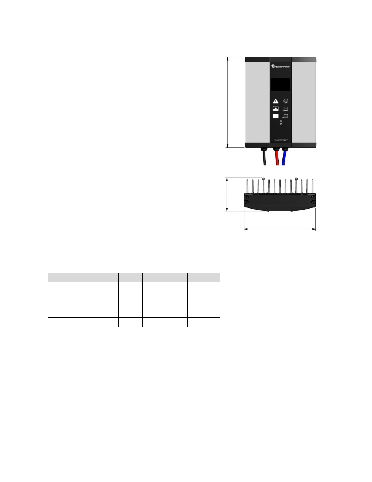
8 Dimensions
Approximate dimensions in mm.
Height excluding cable clamps.
Weight including standard cables, excluding accessories and package.
model
height
width
depth
weight kg
Robust 1100 passive
290
230
110
5.8
Robust 1100 fan
330
230
80
3.9
Robust 2300 passive
330
230
110
8.5
Robust 2300 fan
370
230
80
6.1
Robust 3000 fan
370
230
80
 Loading...