

Powerfinn PAC 600, PAC 800, PAC 1600 Installation And User Manual
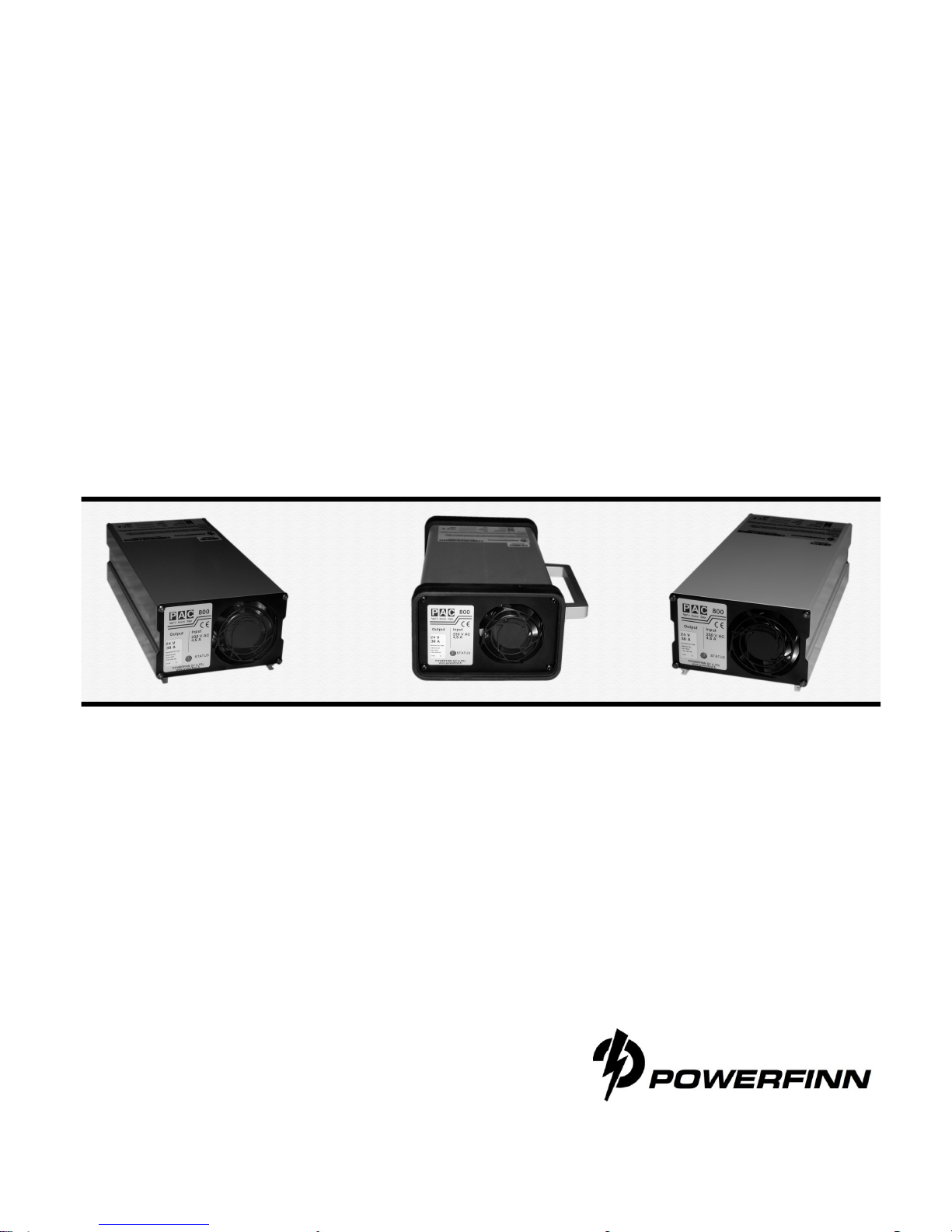
PAC 600
PAC 800
PAC 800 comfort
Installation and User Manual
Advanced Battery Chargers

Table of
contents
POWERFINN PAC 600/800.......................2
General....................................................... 2
Installation..................................................3
Operations.................................................. 4
Safety Instructions......................................5
Troubleshooting and repair........................6
Guarantee..................................................6
Appendix A.................................................6
Appendix B................................................. 7
Appendix C................................................. 7
Important
Read this manual before installing or operating the battery charger.
It must be ensured that children do not play with the device.
PAC 600
PAC 800
Powerfinn PAC 600 and PAC 800 battery chargers use modern
switching technology. The intelligent micro controller extends the life of
the battery by supervising the charging process. The charger is
compact, lightweight and meets the EU safety and EMC requirements.
General
PAC chargers are available for a variety of battery types. The charger
type is indicated on the label attached to the side of the charger.
Be sure to always use the correct type of charger. The charger type
should correspond to the battery construction (sealed, vented, etc.)
Attempting to charge a battery with the wrong type of charger may
result in considerable damage.
Check the battery to ascertain that the “five hour capacity” (in amperehours, Ah5) is between 5 and 14 times greater than the nominal
current (in amperes) of the charger. E.g. a 10A charger is suitable for
charging batteries with a 5-hour capacity of 50Ah-140Ah.
2

Installation
The following points must be respected when choosing a location for
the charger.
1. The location must be dry, dust-free and indoors. The acceptable
temperature range for operation is 0°C to +40°C. A higher ambient
temperature will limit the current supply, see appendix A on page 6.
Caution: The charger is not waterproof. Keep the charger dry and
away from areas with high humidity in order to avoid the risk of
electrical shock and damage to the charger.
2. The equipment may be installed horizontally or vertically. The
horizontal position, however, is recommended with a height of 1
meter above floor level.
3. To ensure sufficient ventilation, leave a free space of at least 10 cm
around all sides of the charger. Do not cover the unit.
4. The charging process generates explosive hydrogen gas. Keep the
area well ventilated. Never use an open flame and avoid sparks
close to the battery and charger.
5. The floor and material below the charger must be fire-resistant.
Install the charger using the railed assembly plate (see figure). With
vertical mounting, place the vertical slide barrier downwards. Fasten
the assembly board to the wall using the mounting holes in the back
of the board. Next, place the charger in the assembly board by
inserting the rails at the bottom side of the charger, into the rail
guides. Finally, fasten the charger to the assembly board by using
the small screws on the side of the board. Fix the sticker (see
appendix C), if provided, to the topside of the charger. Plug the main
power cord into an earthed mains outlet.
3
 Loading...