

Page 1
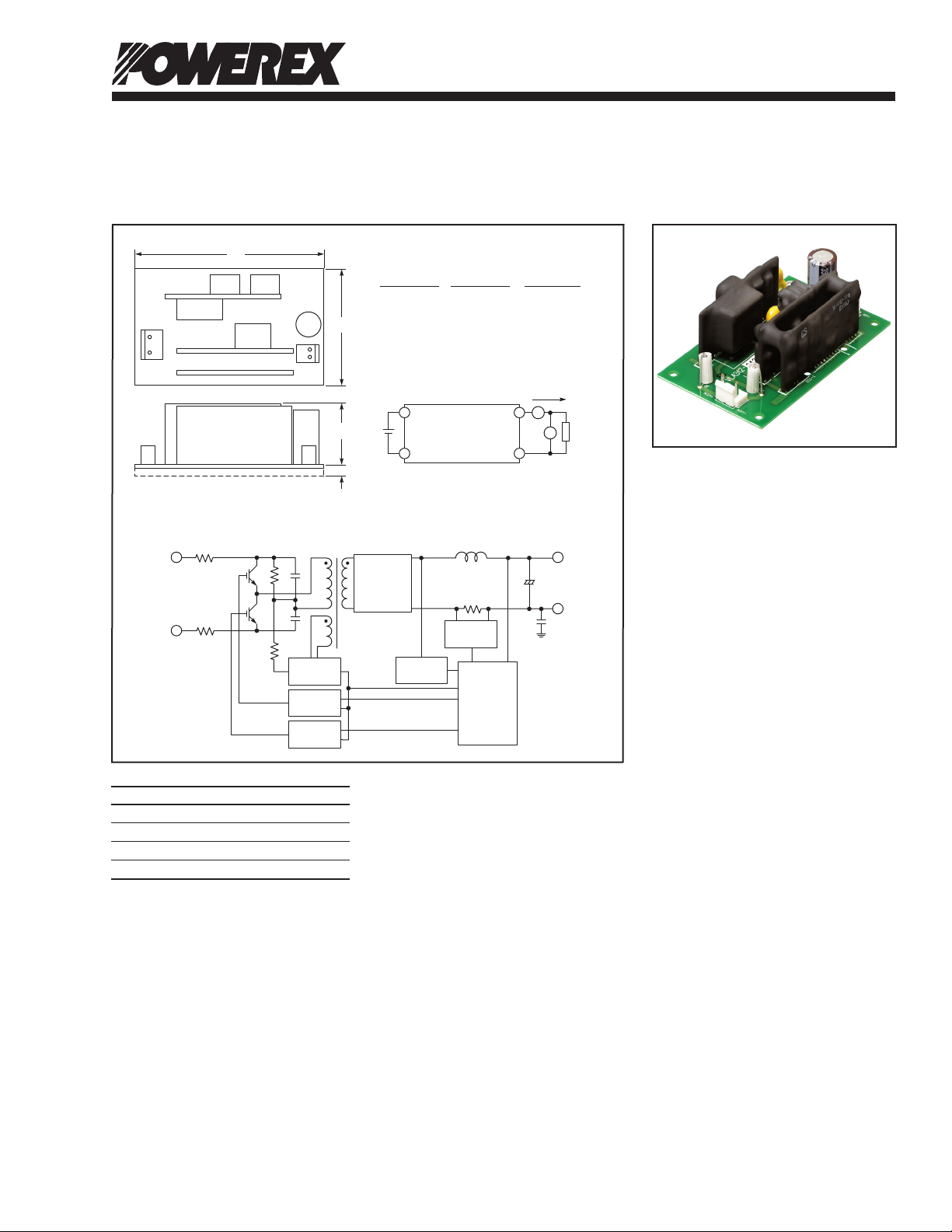
VLA312-2425
A
B
CN1 CN2
Parts No. B2P3-VH, JST B2P-VH, JST
Polarity (Pin 1) -VIN +V
O
Polarity (Pin 2) — -V
O
Polarity (Pin 3) +VIN —
CONNECTOR
TEST CIRCUIT DIAGRAM
BLOCK DIAGRAM
CN1
CN2
C
D
CURRENT
SENSING
CONTROL
POWER
MAIN
CONTROL
RECTIFIER
GATE
POWER
HIGH SIDE
DRIVE
A
LOAD
VLA312-2425
V
V
IN
V
O
+V
O
+
−V
O
+V
IN
−V
IN
FG
I
O
+ +
− −
LOW SIDE
DRIVE
Powerex, Inc., 173 Pavilion Lane, Youngwood, Pennsylvania 15697 (724) 925-7272
Isolated
DC-DC Converter
Description:
VLA312-2425 is an isolated DC-DC
converter designed for industrial equipment.
It is designed to convert a rectified line
voltage ranging from 475 to 850V DC into
24V DC. Total output power is 25W.
Features:
£ Input Voltage Range:
475V to 850V DC
£ Output: +24V, 1.05A
(Output Power: 25.2W)
£ Electrical Isolation Voltage
Between Input and Output:
2500 V
for 1 Minute
rms
£ Over-current Protection
Outline Drawing and Circuit Diagram
Dimensions Inches Millimeters
A 3.54 90.0
(Auto Resumption)
£ Over-voltage Protection
Application:
On-board pre-regulator for
industrial control equipment.
B 2.16 55.0
C 1.38 35.0
D 0.20 5.0
105/09
Page 2
Powerex, Inc., 173 Pavilion Lane, Youngwood, Pennsylvania 15697 (724) 925-7272
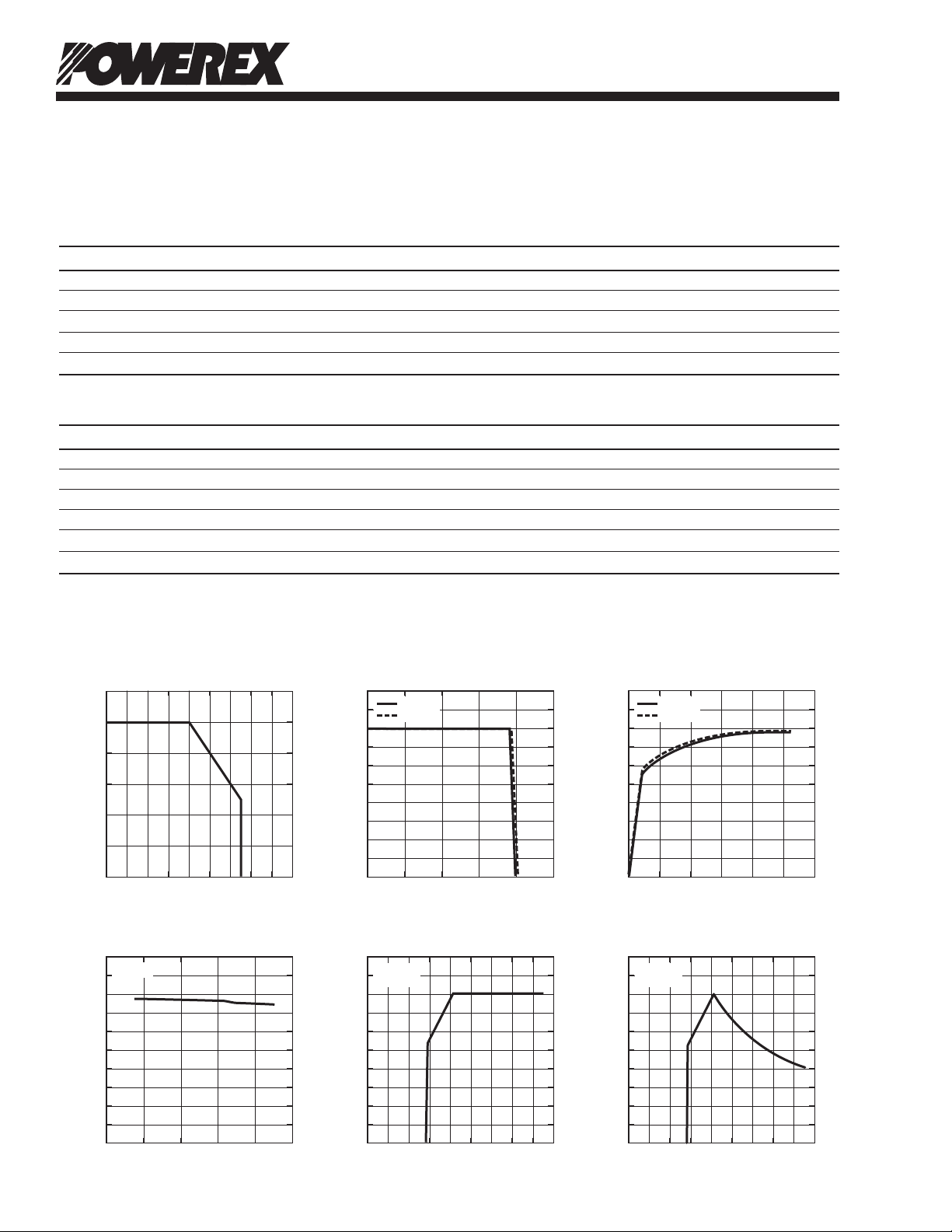
OUTPUT CURRENT, IO, (mA)
EFFICIENCY, η, (%)
EFFICIENCY VS. OUTPUT CURRENT
CHARACTERISTICS
100
0 0.2 0.4 0.6 1.21.00.8
80
90
60
70
40
50
10
20
30
0
0.10
0.08
0.09
0.06
0.07
0.04
0.05
0.01
0.02
0.03
0
OUTPUT CURRENT, IO, (mA)
OUTPUT VOLTAGE, V
O
, (VOLTS)
OUTPUT VOLTAGE VS. OUTPUT CURRENT
CHARACTERISTICS
30
0 2.01.0 1.50.5 2.5
9
12
15
18
21
24
27
6
3
0
INPUT VOLTAGE, VIN, (VOLTS)
EFFICIENCY, η, (%)
EFFICIENCY VS. INPUT VOLTAGE
CHARACTERISTICS
400 500 600
800
700 900
IO = 1.05A
0 100 200 300 400 500600 800700 900 0 100 200 300 400 500 600 800700 900
RL = 22.9Ω
(I
O
= 1.05A)
RL = 22.9Ω
(I
O
= 1.05A)
INPUT VOLTAGE, V
IN
, (VOLTS)
OUTPUT VOLTAGE, V
O
, (VOLTS)
OUTPUT VOLTAGE VS. INPUT VOLTAGE
CHARACTERISTICS
INPUT VOLTAGE, VIN, (VOLTS)
INPUT CURRENT, I
IN
, (A)
INPUT CURRENT VS. INPUT VOLTAGE
CHARACTERISTICS
AMBIENT TEMPERATURE, (°C)
OUTPUT CURRENT DE-RATING, (%)
DE-RATING
CHARACTERISTICS
120
-10 100 8020 30 40 50 60 70
100
80
60
40
20
0
VIN = 680V
V
IN
= 600V
VIN = 680V
V
IN
= 600V
100
80
90
60
70
40
50
10
20
30
0
30
9
12
15
18
21
24
27
6
3
0
VLA312-2425
Isolated DC-DC Converter
Absolute Maximum Ratings, Ta = 25°C unless otherwise specied
Characteristics Symbol VLA312-2425 Units
Input Voltage V
IN
850 Volts
Output Current IO 1.05 A
Operating Temperature (No Condensation)*1 T
Storage Temperature (No Condensation) T
Input-Output Isolation Voltage (Sine Wave Voltage, 60Hz, 1 Minute) V
-10 ~ +55 °C
opr
-20 ~ +75 °C
stg
2500 V
ISO
rms
Electrical and Mechanical Characteristics, Ta = 25°C, VIN = 680V unless otherwise noted
Characteristics Symbol Test Conditions Min. Typ. Max. Units
Input Voltage VIN Recommended Range 475 680 850 Volts
Output Voltage 1 VO I
Input Regulation R
Load Regulation R
Ripple Voltage V
I
eg-I
I
eg-L
IO = 1.05A*2 — — 240 mV
P-P
Efficiency h I
*1 Please refer to de-rating characteristics.
*2 Not including spike noise.
= 0.1 ~ 1.05A 22.8 24.0 25.2 Volts
O
= 1.05A, VIN = 475 ~ 850V — — 100 mV
O
= 0.1 ~ 1.05A — — 150 mV
O
= 1.05A — 77 — %
O
2 05/09
Page 3

Powerex, Inc., 173 Pavilion Lane, Youngwood, Pennsylvania 15697 (724) 925-7272
VLA312-2425
Isolated DC-DC Converter
Safety Precautions
Great detail and careful attention are given to the production of HVICs, such as in the development, the quality of production, and in its
reliability. However, the reliability of HVICs depends not only on their own factors but also in how they are used. When handling HVICs
please note the following cautions.
CAUTIONS
Packaging: The materials used in packaging HVICs can only withstand normal external conditions. When exposed to outside shocks,
rain, and certain environmental contamination, the packaging materials will deteriorate. Please take care in handling.
Carrying: 1. Don't stack boxes too high. Avoid placing heavy materials on boxes.
2. Boxes must be positioned correctly during transportation to avoid breakage.
3. Don't throw or drop boxes.
4. Keep boxes dry. Avoid rain or snow.
5. Minimal vibration and shock during transportation is desirable.
Storage: When storing HVICs, please observe the following notices or possible deterioration of their electrical characteristics,
risk of solderability, and external damage may occur.
1. Devices must be stored where fluctuation of temperature and humidity is minimal and must not be exposed to
direct sunlight. Store at the normal temperature of 5 to 30°C with humidity at 40 to 60%.
2. Avoid locations where corrosive gasses are generated or where a lot of dust accumulates.
3. Storage cases must be static proof.
4. Avoid putting weight on boxes.
Extended When extended storage is necessary, HVICs must be kept non-processed. When using HVICs which have been stored for
Storage: more than one year or under severe conditions, be sure to check that the exterior is free from flaws or other damage.
Maximum To prevent any electrical damage, use HVICs within the maximum ratings. The temperature, current, voltage, etc., must
Ratings: not exceed these conditions.
Polarity: To prevent HVICs from destruction and deterioration due to wrong insertion, make sure polarity of inserting leads into
the board hole conforms to the external view for the terminal arrangement.
305/09
 Loading...