

Page 1
TA20
*
*Other lead code options available
1800A
Powerex, Inc., 200 Hillis Street, Youngwood, Pennsylvania 15697-1800 (412) 925-7272 Phase Control SCR
Powerex, Europe, S.A.
428
Avenue
G.
Durand, BP107, 72003
LeMans,
France (43) 41.14.14 1800 Amperes Average
2200 Volts
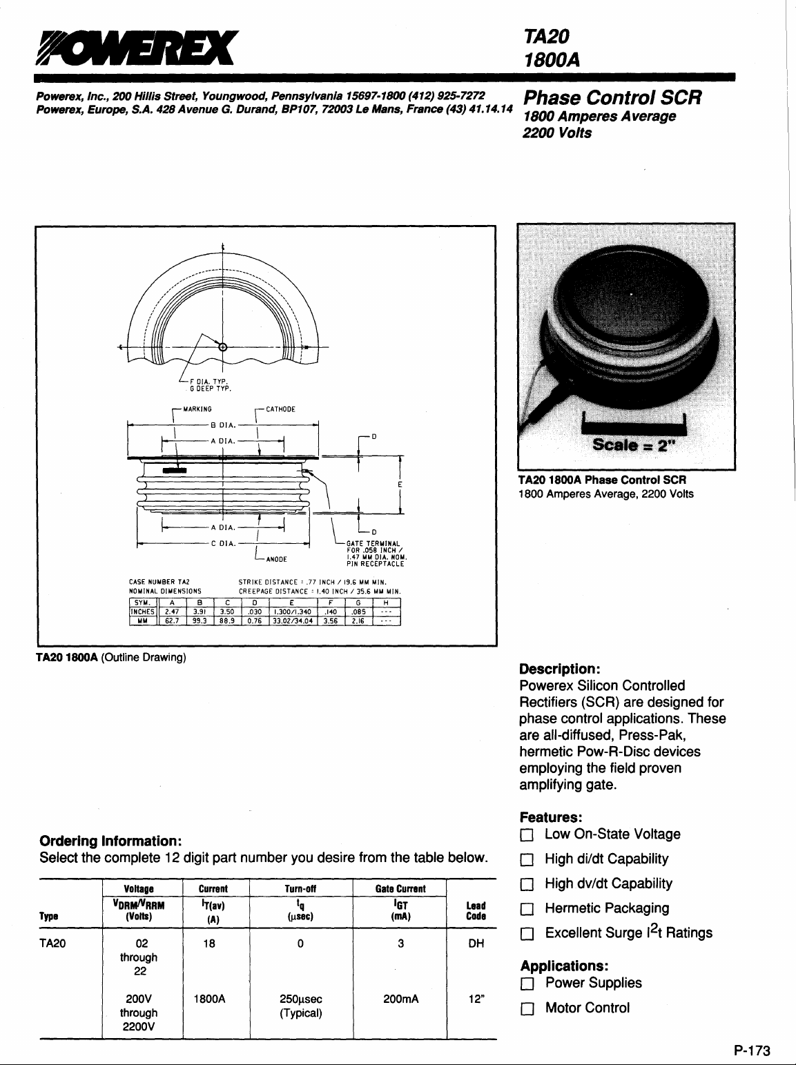
CASE
NUMBER
TA2
TA20 1800A (Outline Drawing)
STRIKE
DISTANCE' .77
INCH / 19.6
MM
MIN.
Ordering Information:
Select the complete 12 digit part number you desire from the table below.
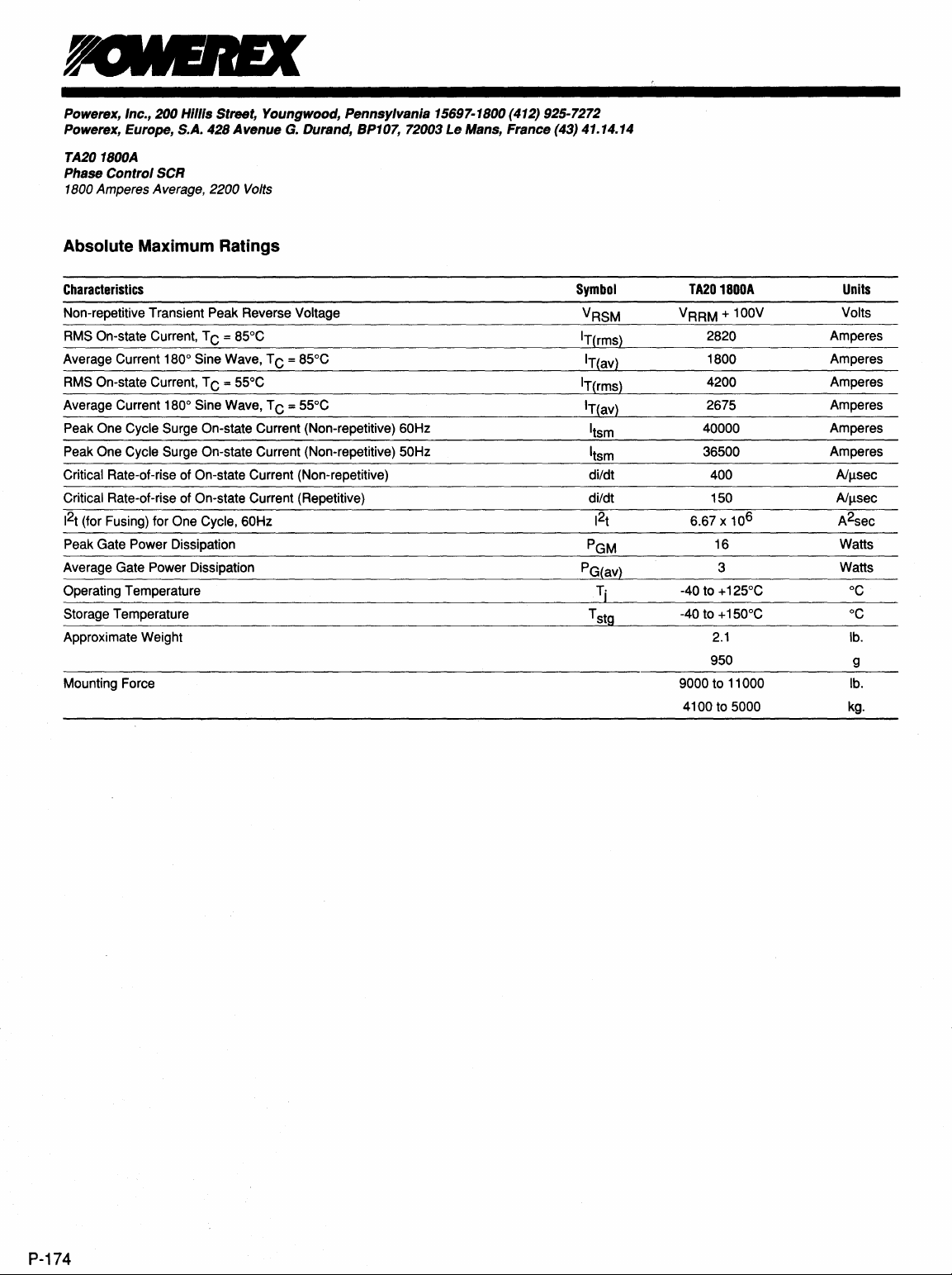
TA20 1800A
1800
Phase
Control
Amperes Average, 2200 Volts
SCR
Description:
Powerex Silicon Controlled
Rectifiers (SCR) are designed for
phase control applications. These
are all-diffused, Press-Pak,
hermetic Pow-R-Disc devices
employing the field proven
amplifying gate.
Features:
o Low On-State Voltage
o High di/dt Capability
Voltage
Type
TA20
VORMlYRRM
(Volts)
02
through
22
200V 1800A
through (Typical)
2200V
Current
Iy(av)
(A)
18 0 3 DH
Turn-off
Iq
(Ilsec)
250fJ,sec
Gate
Currant
IGT
(mA)
200mA 12"
Lead
Code
o High dv/dt Capability
o Hermetic Packaging
2
o Excellent Surge 1
Applications:
o Power Supplies
o Motor Control
t
Ratings
P-173
Page 2
Powerex, Inc., 200 Hillis Street, Youngwood, Pennsylvania 15697-1800 (412) 925-7272
Powerex, Europe, S.A.
428
Avenue
G.
Durand, BP107, 72003 Le Mans, France (43) 41.14.14
TA201800A
Phase Control SCR
1800 Amperes Average, 2200 Volts
Absolute Maximum Ratings
Characteristics
Non-repetitive Transient Peak Reverse Voltage
On-state Current, T C = 85°C
RMS
Average Current 180° Sine Wave, T C = 85°C
RMS On-state Current, T C = 55°C
Average Current 180° Sine Wave, T C = 55°C
Peak One Cycle Surge On-state Current (Non-repetitive) 60Hz I
Peak One Cycle Surge On-state Current (Non-repetitive) 50Hz
Rate-of-rise of On-state Current (Non-repetitive) di/dt
Critical
Critical Rate-of-rise of On-state Current (Repetitive)
2
1
(for Fusing) for One Cycle, 60Hz 1
t
Peak Gate Power Dissipation
Average Gate Power Dissipation
Operating Temperature
Storage Temperature T
Approximate Weight
Mounting Force
Symbol
VRSM
IT(rms}
IT(rms}
PG(av}
IT(av}
IT(av}
tsm
I
tsm
di/dt
2
t
PGM
Tj
stg
TA201800A
VRRM + 100V
2820
1800
4200
2675
40000
36500
400
150
6.67 x 10
-40 to + 125°C
-40
9000 to
4100
6
16 Watts
3
to + 150°C
2.1
950
11
000 lb.
to 5000 kg.
Units
Volts
Amperes
Amperes
Amperes
Amperes
Amperes
Amperes
sec
A/Il
sec
A/Il
A2sec
Watts
°C
°C
lb.
g
P-174
Page 3

Powerex, Inc., 200 Hillis Street, Youngwood, Pennsylvania 15697-1800 (412) 925-7272
jPowerex, Europe, S.A.
428
Avenue
G.
Durand, BP107, 72003
Le
Mans, France (43) 41.14.14
TA201800A
Phase Control SCR
1800 Amperes Average, 2200 Volts
Electrical Characteristics, Tj = 25°C Unless Otherwise Specified
Characteristics
Repetitive Peak Reverse Leakage Current
Repetitive Peak Forward Leakage Current
Peak On-state Voltage
Threshold Voltage, Low-level
Slope Resistance,
Threshold Voltage, High-level
Resistance, High-level
Slope
VTM Coefficients,
VTM Coefficients, High-level
Typical
Turn-on Time
Typical Turn-off Time
Minimum
Gate Trigger Current
Gate Trigger
Non-Triggering Gate Voltage
Peak Forward Gate Current
Peak Reverse Gate Voltage
Critical dv/dt - Exponential to V DRM
LOW-level
LOW-level
Voltage
Symbol
IRRM
IDRM
VTM
V(TO)
rT1
V(TO)2
rT2
dv/dt
Test
Conditions
Tj = 125°C, VR = VRRM
= 125°C, VD = VDRM
Tj
ITM = 3000A Peak
Cycle < 0.1%
Duty
Tj = 125°C, I = 15%, IT(av) to nIT(av)
1
Tj = 125°C, I = nIT(av) to ITSM
Tj = 125°C, I = 15% IT(av) to nIT(av)
= 1000A, VD = 1500V
IT
Tj = 125°C, IT = 250A,
diR/dt = 50AlJlsec Reapplied
dv/dt = 20V/Jlsec Linear to
80% VDRM
Min.
300
Typ.
A1
8
C1
0
A2 = -6.7846
82
C2
02
4
250
1
1
Max.
100
100
1.45 Volts
0.71870 Volts
0.1669
0.97647
0.1215
Units
rnA
rnA
mQ
Volts
mQ
= 1.0791
= -0.12551
= 3.874E-06
= 0.02151
= 1.1619
= 1.858E-04
= -0.03560
Jlsec
Jlsec
V/Jlsec
200
3.0
0.15
4
5
rnA
Volts
Volts
A
Volts
Thermal. Characteristics
Maximum Thermal Resistance, Double Sided Cooling
Junction-to-Case
. Case-to-Sink
Re(j-c)
Re(c-s)
0.015
0.007
°C/W
°C/W
P-175
Page 4

Powerex, Inc.,
Powerex, Europe, S.A. 428
TA20 1800A
Phase
1800 Amperes Average, 2200 Volts
Control
200
SCR
Hillis
Street,
Avenue
Youngwood,
G.
Pennsylvania
Durand, BP107, 72003
15697-1800 (412) 925-7272
Le
Mans,
France
(43) 41.14.14
Maximum On-State Forward Voltage Drop
5
! 4
E
;:
~
3
o
10
4000
13500
H~~~
~
';3000
.S2
i
2500
'i
is
2000
11500
~
1000
i500
~
o
o
200
(TJ = 125
OC)
/
........
~
100
Instantaneous
Maximum On-State Power Dissipation
(Sinusoidal Waveform)
/
v~
/
~v
/~
~-
400
600
Average On-State Current -It(av) -Amperes
On-State
3O
V
/
~
800
1000
CUrrlnt -Itm -Amperes
600
1
V
°
~
/
V/
/:
~v
'/"
.~
O(~DU
1000 1200
1400
1600 1800
10000
/
/'
/'
\
\
~80
~ON
~L
V
/
120
V
2000
/
3IIl
2200
100000
'''''0
2400
0.Q16
Pi
0.014
0,
0.012
~
,
I
i
0.008
.5
0.006
'ii
!
0.004
•
~
0.002
130
u
0,
120
I
~
110
;
100
i
1-90
{!
•
B
-
0.01
80
70
60
;.---
o
0.001
0
Maximum Transient Thermal Impedance
(Junction
to
Ca.e)
I
1TA20-1e
V
i'
/
..........v
0.01
Maximum Allowable Case Temperature
500
Average On-$tate Current
0.1
Time - t - Seconds
(Sinusoidal Waveform)
1000
1500
-It(av)
- Amperes
~
/"'-
10
2000
100
2500
P-176
Maximum On-State Power Dissipation
5000
i
~4000
c
.S2
J3000
12000
1----+----f+~¥7"S..-=±:=:--+-+-__+____1
E
::I
1000
1
o
o
500
Average
(Rectangular Waveform)
1000 1500
On-8tate
2000
Cu
.....
nt
2500
-It(av) -
3000
seoo
Amperaa
4000
130
P
120
1110
~
~
100
i
90
I.
!
80
~
70
-:
40
Maximum Allowable Case Temperature
(Rectangular Waveform)
~
~
~
\~
\"-
\
~
~
\
\
"'''
0
\130
~
,,""
\.'\.
-:IV
00
o
500
1000 1500
Average
On-8tate
..--
IT
VCOfI
~
",,-"-
120°",,-
2000 2500
Currwnt
It(av)
1io
oucnON
MalE
~
80~
~
'v
3000
Amperaa
380
"
:reo
seoo
o
4000
 Loading...