

Page 1
TA20
*
*Other lead code options available
1600A
Powerex,lnc., 200 Hi/lls Street, Youngwood, Pennsylvania 15697-1800 (412) 925-7272 Phase Control
Powerex, Europe, S.A.
428
Avenue
G.
Durand, BP107, 72003
Le
Mans, France (43) 41.14.14 1600 Amperes Average
2200 Volts
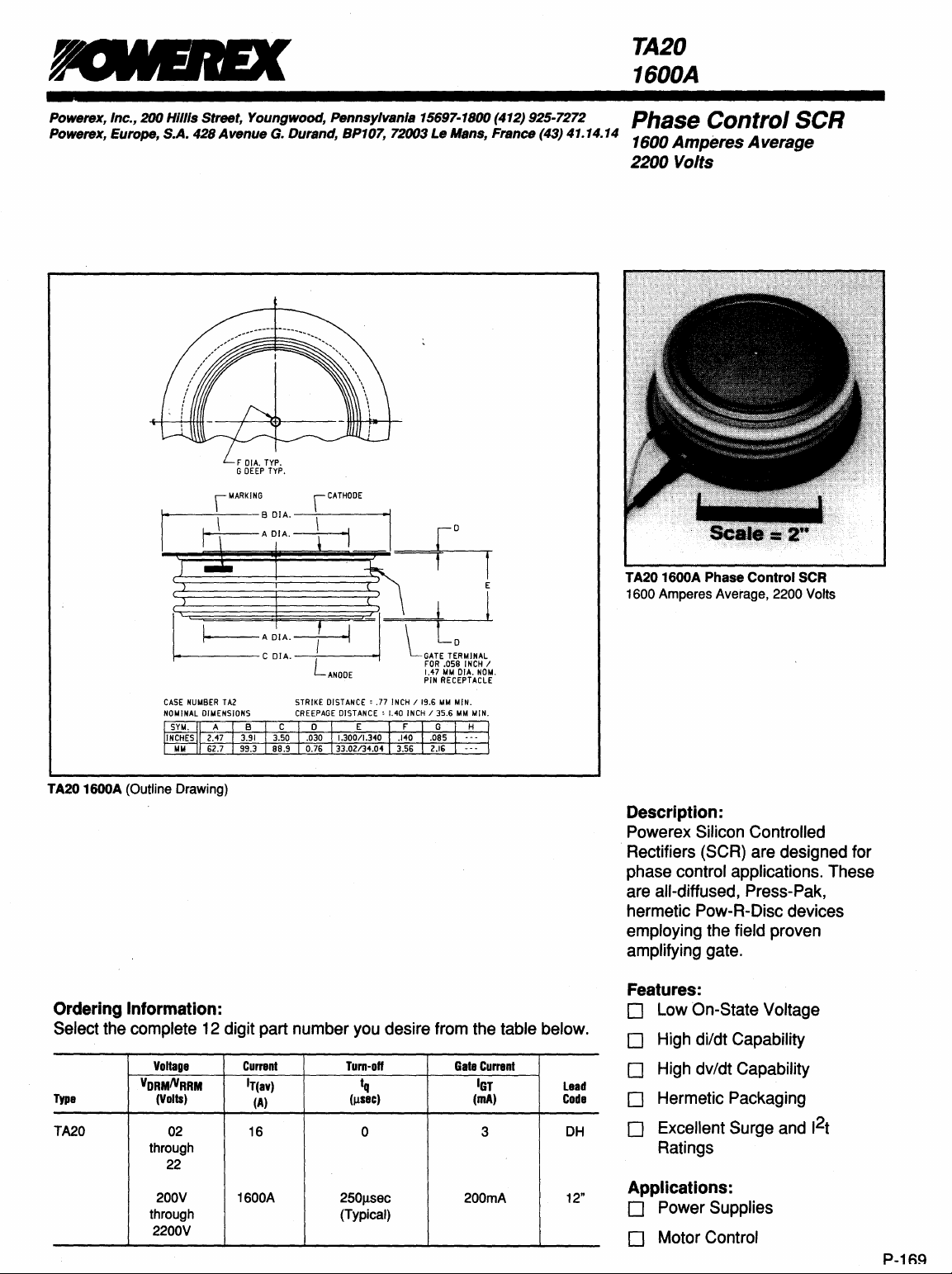
TA20 1600A
1600
Phase
Control
Amperes Average, 2200 Volts
SCR
SCR
TA20 1600A (Outline Drawing)
Ordering Information:
Select the complete 12 digit part number you desire from the table below.
Type
TA20 02
VORMIVRRM
through
through
Voltage
(Volts)
22
200V 1600A
2200V
Current
IT(av)
(A)
16
Turn-off
tq
(Illec)
0 3
250Jlsec 200mA
(Typical)
Gate
Currant
IGT
(mA)
lead
Code
DH
12"
Description:
Powerex Silicon Controlled
Rectifiers
(SCR) are designed for
phase control applications. These
are all-diffused, Press-Pak,
hermetic Pow-R-Disc devices
employing the field proven
amplifying gate.
Features:
o Low On-State Voltage
o High di/dt Capability
o High dv/dt Capability
o Hermetic Packaging
o Excellent Surge and 1
Ratings
Applications:
o Power Supplies
o Motor Control
2
t
P-1RQ
Page 2
Powerex, Inc.,
20D
HIllis Street, Youngwood, Pennsylvania 15697·1800 (412) 925·7272
Powerex, Europe, S.A. 428 Avenue
TA2D
1600A
Phase
Control
1600
Amperes Average, 2200
SCR
Volts
Absolute Maximum ~ .. tings
G.
Durand, BP107, 72003 Le Mans,
France
(43) 41.14.14
Characteristics
Non-repetitive Transient
RMS
On-state
Average
RMS
On-state Current, T C =
Average
Peak
One
Peak
One
Critical Rate-of-rise of On-state Current (Non-repetitive)
Critical Rate-of-rise
2
t
1
(for
Peak
Gate
Average
Operating Temperature
Storage
Approximate Weight
Mounting
Current,
Current 180°
Current
Cycle
Cycle Surge On-state Current (Non-repetitive) 50Hz I
Fusing)
for
Power
Gate Power Dissipation
Temperature
Force
Peak
Reverse Voltage
T C =
80°C
Sine
Wave,
T C =
80°C
55°C
180°
Sine
Wave,
T C =
55°C
Surge
On-state Current (Non-repetitive) 60Hz I
of
On-state Current (Repetitive)
One
Cycle,
60Hz
Dissipation
Symbol
VRSM
IT(rms)
IT(av)
IT(rms)
IT(av)
tsm
tsm
di/dt
di/dt
2
t
1
PGM
PG(av)
Tj
T
stg
TA201600A
VRRM
+ 100V
2500
1600
3390
2160
29500
26900
400
150
3.63 x
16
3
-40
to + 125°C
-40
to + 150°C
2.1
950
9000
to
11
4100
to
6
10
000
5000
Units
Volts
Amperes
Amperes
Amperes
Amperes
Amperes
Amperes
AlJlsec
AlJlsec
A2sec
Watts
Watts
°C
°C
lb.
g
lb.
kg.
P-170
Page 3

Powerex, Inc.,
Powerex, Europe, S.A. 428
TA20 1600A
Phase
1600 Amperes Average, 2200 Volts
Control
200
SCR
Hillis
Street,
Avenue
Youngwood,
G.
Pennsylvania
Durand, BP107, 72003
15697-1800 (412) 925-7272
Le
Mans,
France
(43) 41.14.14
Electrical Characteristics, Tj = 25°C Unless Otherwise Specified
Characteristics
Repetitive Peak Reverse Leakage Current
Repetitive Peak Forward Leakage Current
Peak On-state Voltage
Threshold Voltage, Low-level
Slope Resistance, Low-level
Threshold Voltage, High-level
Slope
Resistance, High-level
VTM Coefficients, Low-level
VTM Coefficients, High-level
Typical Turn-on Time
Typical Turn-off Time
Minimum Critical dv/dt - Exponential to
Gate Trigger Current
Gate Trigger
Non-Triggering Gate Voltage
Peak Forward Gate Current
Peak Reverse Gate
Voltage
Voltage
VORM dv/dt
Symbol
IRRM
10RM
VTM
V(TO) 1
rT1
V(TO)2
rT2
tan
Test
Conditions
Tj = 125°C, VR = VRRM
Tj = 125°C,
ITM
Outy
Tj = 125°C, I = 15%, IT(av) to 1tIT(av)
Tj = 125°C, I = 1tIT(av) to ITSM
Tj = 125°C, I = 15% IT(av) to 1tIT(av)
ITM
Tj = 125°C, IT = 250A,
diR/dt =
dv/dt
Vo
= 3000A Peak
Cycle < 0.1%
= 1000A,
=
Vo
50AlJ.lSec
20V/~sec
80% VORM
= VORM
= 1500V
Reapplied
Linear to
Min.
300
Typ.
A1
81
C1
01
A2 = -3.7832
82
C2
02
4
250
Max.
100 rnA
100
1.75
0.89109 Volts
0.2148 mO
1.7405 Volts
0.1024 mO
Units
rnA
Volts
= 1.1219
= -0.10195
= 4.764E-05
= 0.02077
= 0.56271
= 3.607E-05
= 0.010389
~sec
J.lSec
V/~sec
200
3.0
0.15
4
5
rnA
Volts
Volts
A
Volts
Thermal Characteristics
Maximum Thermal Resistance, Oouble Sided Cooling
Junction-to-Case
Case-to-Sink
RO(j-c)
RO(C-s)
0.015
0.007
P-171
Page 4

Powerex, Inc.,
Powerex,
TA201600A
Phase
1600 Amperes Average,
Europe,
Control
200
SCR
Hillis
S.A.
Street,
428
Avenue
2200
Youngwood,
G.
Volts
Durand,
Pennsylvania
BP107, 72003
15697-1800 (412) 925-7272
Le
Mans,
France
(43) 41.14.14
Maximum On-State Forward Voltage Drop
(T)
= 125
°C)
v
I
I
/
......
! 4
5
jTLle
3
V
o
10
3000
r--""---r--...,...-...,..-""'T""-"""T"-~-~--"
!
2500
t--+---t---+---+---i---+-7'4ifIo"T--+-__i
c
100 1000
Instantaneous On-$tate Current - Itm - Amperes
Maximum On-State Power Dissipation
(Sinusoidal Waveform)
10000
100000
i::t--+----t-~A-_T~~~~-+~-+---+--__i
J1000~--~~~~~~--~--~~4---+-~
E
i~~~~~~~~~~
o
~ ~
Average On-State Current -It(av) - Amperes
~
~
1~
1~
1~
1~ 1~
0.016
~
o
0.012
~
8
.8
0.008
It
..§
ii
!§
0.004
.!!
...
130
o
120
I
t!-
o
110
;
100
1
E
{!!
90
B
i
80
70
o
0.001
Maximum Transient Thermal Impedance
(Junction
to
Case)
m.
V
/v
.....
..Y
V
~""'"
o
0,01
Maximum
~ ~
Average On-$tate Current
0.1
Time - t - Seconds
Allowable Case Temperature
(Sinusoidal Waveform)
~
~
1000
-It(av)
"
10
1~
1400 1600 1800
- Amperes
V
....
100
P-172
4000
i
&3000
i
12000
J
~1~
I
o
Maximum On-State Power DlsslpaUon
(Rectangular Waveform)
ITAro.1S1
o
~
Average On-State Current -It(av) -Amperes
1~
1500
2000
110
ANGLE
2500
360·
380
3000
Maximum Allowable Case Temperature·
130
~--~-
~
1~
t-~~~---+----+--~~----~~--~
J
110
t--3~~~~-lt;;J:+:==::;:=:;=::::::;-1
o
2
100
t---~~~~~~~~~~~~~r-~~
!
90
It
!
80
J
70
i
60
:Ii
50
o
(Rectangular Wavefonn)
.....
...,.. .......... ~ .......... ~ ..........
~
1000
Average On-State Current It(av) Amperes
1~
2000
~~--~
2500
3000
 Loading...