

Page 1
T820
Other lead code options available
9DDA
Powerex, Inc., 200 Hillis Street, Youngwood, Pennsylvania 15697-1800 (412) 925-7272 Phase Control SCR
Powerex, Europe, S.A. 428 Avenue
G.
Durand, SP107, 72003 Le Mans, France (43) 41.14.14 900 Amperes Average
1600 Volts
CATHODE
POTENTIAL TERMINAL
FOR
.187
INCH
14.75
MM
PUSH'ON
TYPE
TERMINAL
NOM.
rMAR'ING
r-:::::-h_1
I~"~IW
~:::::~
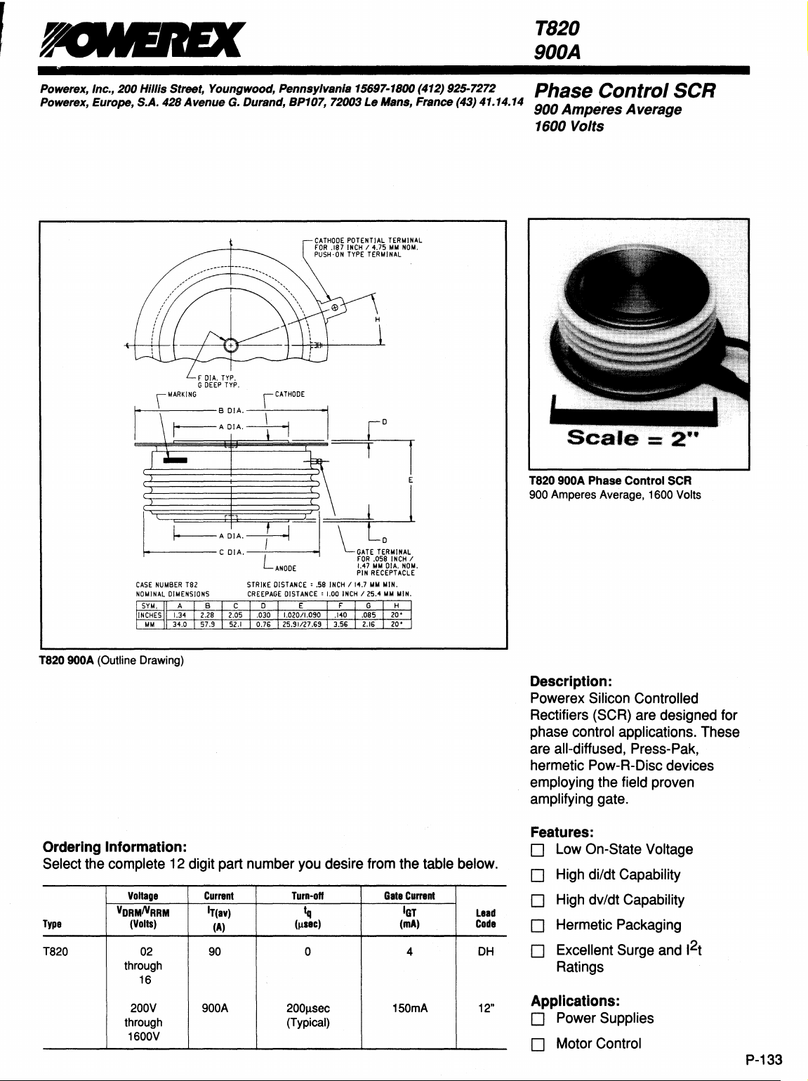
CASE
NUMBER
NOMINAL
DIMENSIONS
SYM.
INCHES
1.34
MM
34.0 57.9
T820 900A (Outline Drawing)
iCATHODE
L
Ta2 STRIKE
ABC
2.28 2.05 .030 1.020/1.090
CREEPAGE
0
52.1
0.76 25.91127.69 3.56
ANODE
DISTANCE'
DISTANCE'
ErG
F 1
E
"-GATET~RMINAL
FOR
.058
INCH
1
:M~M~~'
MM
MIN.
MM
MIN.
H
20'
ZO'
.58
INCH
1.00
.140
~i1J
114.7
INCH
12S.4
.085
2.16
T820 900A Phase
Amperes Average, 1600 Volts
900
Control
SCR
Description:
Powerex Silicon Controlled
Rectifiers (SCR) are designed for
control applications. These
phase
are
all-diffused, Press-Pak,
hermetic Pow-R-Disc devices
employing the field proven
amplifying gate.
Ordering Information:
Select the complete 12 digit part number you desire from the table below.
Type
VORMNRRM
T820
Voltage
(Volts)
02 90 0
through
16
200V 900A
through (Typical)
1600V
Current
IT(av)
(A)
Turn-on
Iq
(Illec)
200!iSec
Gate
Current
IGT
(mA)
150mA 12"
Features:
o Low On-State Voltage
o High di/dt Capability
o High dv/dt Capability
lead
Code
4
DH
o Hermetic Packaging
o Excellent Surge and 1
2
t
Ratings
Applications:
o Power Supplies
o Motor Control
P-133
Page 2
Powereic, Inc.,
Powerex, Europe, S.A. 428
T820900A
Phase
900 Amperes Average, 1600 Volts
Control
200
SCR
Hillis
Street,
Avenue
Youngwood,
G.
Pennsylvania
Durand, BP107, 72003
15697-1800 (412) 925-7272
Le
Mans,
France
(43) 41.14.14
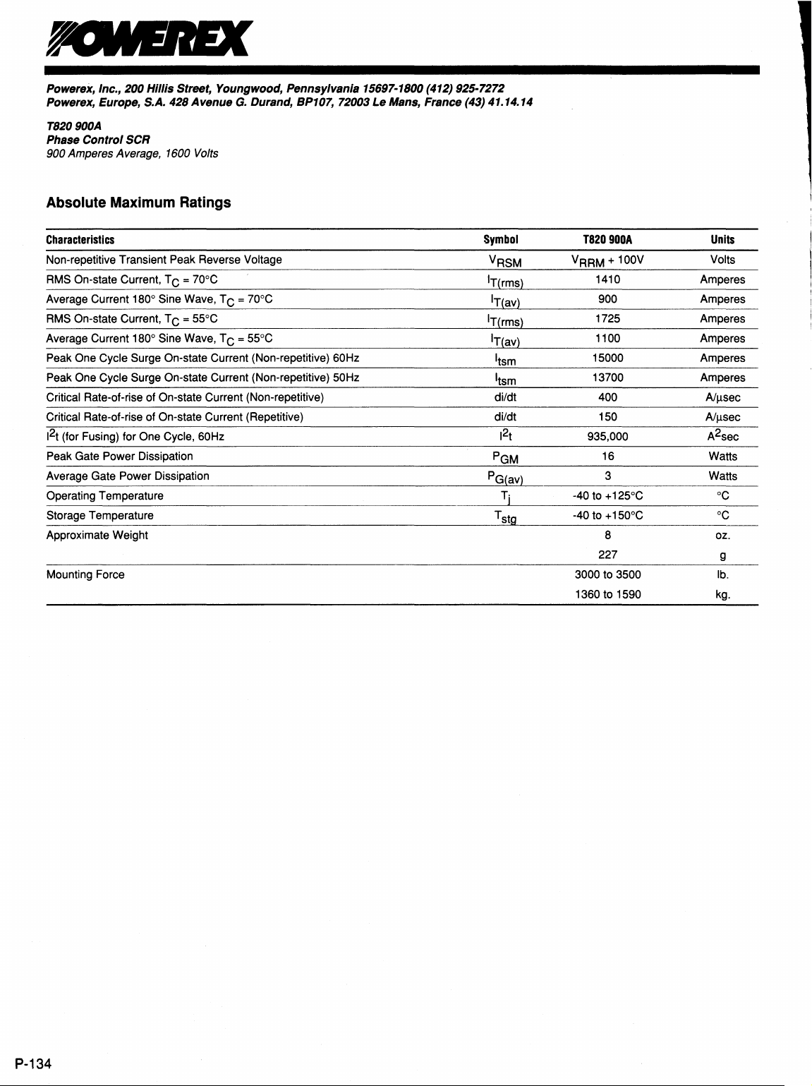
Absolute
Characteristics
Non-repetitive Transient Peak Reverse
RMS
Average Current 180° Sine Wave, T C = 70°C
RMS
Average Current
Peak
Peak One Cycle Surge On-state Current (Non-repetitive) 50Hz
Critical Rate-of-rise of On-state Current (Non-repetitive)
Critical Rate-of-rise of On-state Current (Repetitive)
2
1
(for Fusing) for One Cycle, 60Hz
t
Peak Gate Power Dissipation
Average Gate Power Dissipation
Operating Temperature
Storage Temperature
Approximate Weight
Mounting Force
Maximum
On-state Current, T C = 70DC
On-state Current, T C = 55DC
180° Sine Wave, T C = 55DC
One Cycle Surge On-state Current (Non-repetitive) 60Hz
Ratings
Voltage
Symbol
VRSM
IT(rms)
IT(av)
IT(rms)
IT(av)
I
tsm
I
tsm
di/dt
di/dt
2
t
1
PGM
PG(av)
Tj
Tst9
T820900A
+ 100V
VRRM
1410
900 Amperes
1725
1100 Amperes
15000
13700
400
150
935,000 A2sec
16
3 Watts
-40 to + 125DC
-40 to + 150°C
8 oz.
227 g
3000 to 3500
to 1590 kg.
1360
Units
Volts
Amperes
Amperes
Amperes
Amperes
Nllsec
Nllsec
Watts
DC
DC
lb.
P-134
Page 3

Powerex, Inc., 200 Hillis Street, Youngwood, Pennsylvania 15697-1800 (412) 925-7272
Powerex, Europe, S.A.
428
Avenue
G.
Durand, BP107, 72003 Le Mans, France (43) 41.14.14
T820900A
Phase Control
SCR
900 Amperes Average, 1600 Volts
Electrical Characteristics, Tj = 25°C Unless Otherwise Specified
Characteristics
Repetitive Peak Reverse Leakage Current
Repetitive Peak Forward Leakage Current
Peak On-state Voltage
Threshold Voltage, Low-level
Slope Resistance, Low-level
Threshold Voltage, High-level
Slope
Resistance, High-level
VTM Coefficients,
VTM CoeffiCients, High-level
Turn-on Time
Typical
Typical Turn-off Time
Minimum
Gate Trigger Current
Gate Trigger
Non-Triggering Gate Voltage
Peak Forward Gate Current
Peak Reverse Gate
Low-level
Critical dv/dt - Exponential to VORM
Voltage
Voltage
Symbol
IRRM
10RM
VTM
V(TO)l
rT1
V(TO)2
rT2
dv/dt
Test
Conditions
Tj
= 125°C, VR = VRRM
Tj
= 125°C,
ITM = 1 500A Peak
Duty
Tj = 125°C, I = 15%, IT(av) to ltIT(av)
Tj = 125°C, I = ltIT(av) to ITSM
Tj = 125°C, I = 15% IT(av) to ltIT(av)
= 1
IT
Tj = 125°C, IT = 250A,
di R/dt =
dv/dt =
Tj
Vo
= VORM
Cycle < 0.1%
OOOA,
Vo
50Al~sec
20V/~sec
80% VORM
= 25°C,
Vo
= 600V
Reapplied
Linear to
= 12V
Min.
300
Typ.
200
Max.
1.35
0.78526 Volts
0.3505
1.0789 Volts
0.2311 mf.l
A1
= 0.68865
B1
= -0.04011
C1
= -1.578E-05
01
= 0.025339
A2 = 2.6289
B2
= -0.37766
C2 = 8.873E-05
D2
= 0.034055
5
35
35
150
3.0
0.15
4
5
Units
mA
mA
Volts
mf.l
~sec
~sec
V/~sec
mA
Volts
Volts
A
Volts
Thermal
Maximum Thermal Resistance, Double Sided Cooling
Junction-to-Case
Case-to-Sink
Characteristics
Reo-c)
Re(C-s)
0.037
0.020
P-135
Page 4

Powerex, Inc., 200 Hillis Street, Youngwood,
Powerex, Europe,
T820900A
PhBse Control SCR
900 Amperes Average, 1600
S.A. 428 Avenue
Volts
G.
Durand, BP107, 72003Le MBns, France (43) 41.14.14
Pennsyl"BI'IIB~5697-1800(412)
925-7272
E
;:
3
o
10
1600
!
1400
~20-90
~
1200
.S!
11:
1600
I:
~
o
o
Maximum On-State Forward Voltage Drop
(TJ =
125'C)
1
~2o-",
V
V
100
Instantaneous On-8tate Current - Itm - Amperes
Maximum On-State Power Dissipation
(Sinusoidal Wavefonn)
v/
~
L
~P'
~
~
100
200
300
Average On-State Current - It(av) - Amperes
1000
30
/
0 V
Y"
400
1;-/
500
V~
.
~
0
°c
600 700
10000
/
t\
I
lieu
ON
PNDUC-
II
....
/
12,
AN
800
10/
380
LE
900
100000
IOU·
1000
0.04
~
•
0.03
~
.
I
-II
0.02
!.
.5
ii
i
0.01
o
0.0001
130
~120
----
J
110
;
100
90
1
!
80
J
70
Iii
60
:E
50
o
Maximum Transient Thermal Impedance
(Junction
to
Case)
Ulli
l/
V
~
0.001
Maximum Allowable Case Temperature
~
eJ
100
Average On-8tate Current - It(av) - Amperes
0.01
nme • t •
(Sinusoidal Waveform)
~
~
~'
"""
"\~n
'"
200
300
400
0.1
Seeonds
:::-......
~
~
~
S
500
0
CON
~
"90'
600
17
UC110N
'-....
""12
700
t\
\
1180
800
10
ANGLE
~
900
~o
:
.~
100
1000
P-136
Maximum On-State Power Dissipation
(Rectangular Wavefonn)
o
200
400
600
800
1000
Average On-State Current - It(av) - Amperes
1200
1400
1600
130
I'-.
~120
1110
..
t:"100
i:
!
70
B
60
•
50
40
o
Maximum Allowable Case Temperature
(Rectangular Waveform)
~
~
~
~
~
'\~
'\
\
400
"-.,
~
t'--..'"
,,\
,u
~'"
600
\"-
~B
200
Averege On-8tate Current
'90'
vc
~
1'-..""-
120",,-
800
-It(av)
0
PNDUC11
~
118~
1000
180
~ANGLE
~
-uu·,
1200 1400
- Amperes
380
360'
1600
 Loading...