

Page 1
2 HP - 5 HP Scroll Enclosure Air Compressors
Please read and save these instructions. Read carefully before attempting to assemble, install, operate or maintain the product
described. Protect yourself and others by observing all safety information. Failure to comply with instructions could result in
personal injury and/or property damage! Retain instructions for future reference.
Description
80
10
60
0
6
4
1
20
40
GENERAL
8
2
20
10
140
11
0
kpa
0
160
psi
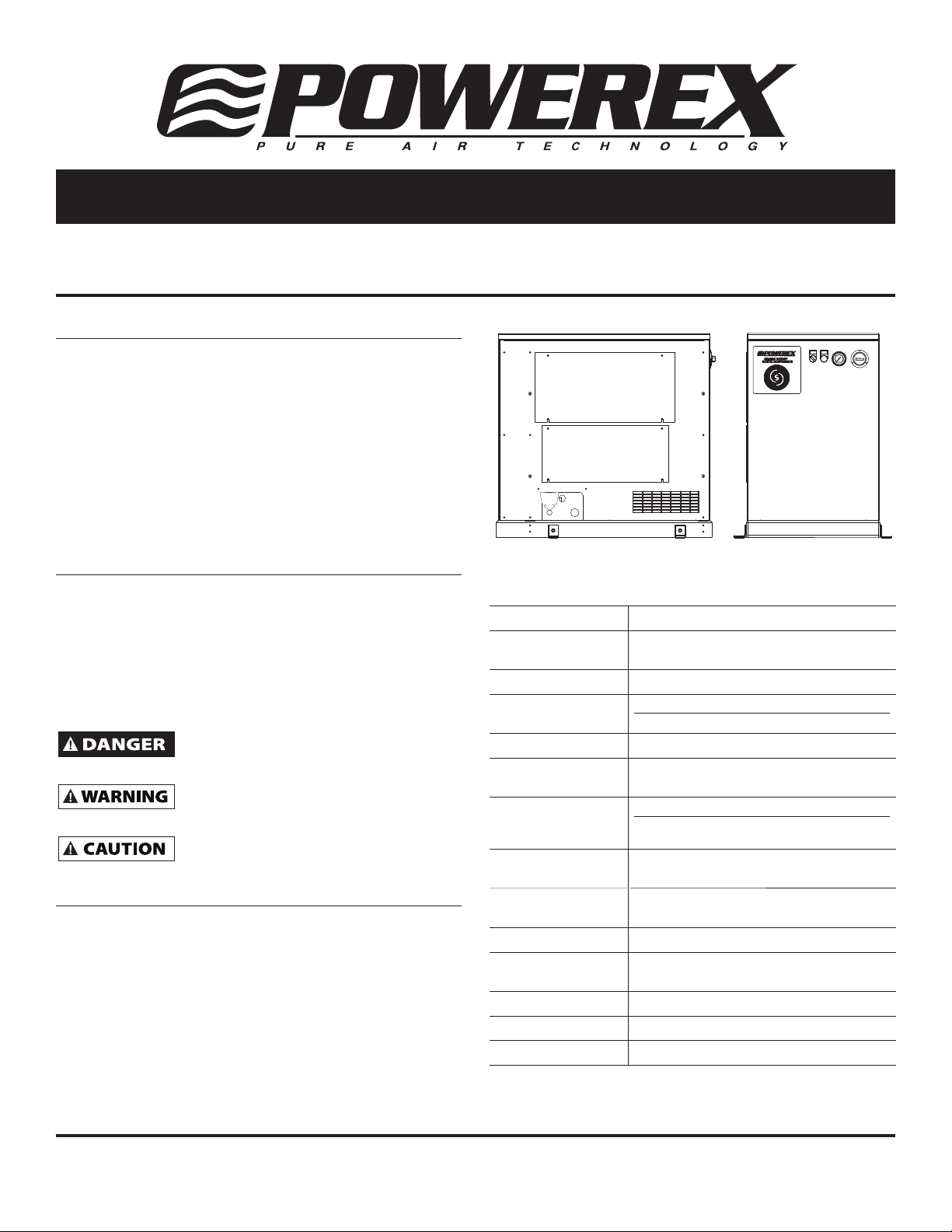
The Powerex Oilless Rotary Scroll Air Compressor has advanced
scroll compressor technology through the development of a
completely oilless compressor. The Powerex Scroll Compressor
offers a dynamically balanced air end which insures vibrationfree operation. The rotary design permits a continuous 100%
duty cycle.
Other standard features on the Powerex Scroll Compressor
:$51,1*
'5$,102,6785()520
include: a Magnetic Starter, Motor Overload Protection, a High
7$1.(9(5<'$<72
35(9(17
7$1.
&25526,21
Temperature Shutdown Switch, an Air Cooled Aftercooler and
a Single Phase or Three Phase 4 Pole ODP motor.
Safety Guidelines
A SEPARATE SAFETY BOOKLET IS PROVIDED ALONG WITH
THIS MANUAL. READ AND UNDERSTAND The SAFETY
BOOKLET. This manual contains information that is very
important to know and understand. This information is
provided for SAFETY and to PREVENT EQUIPMENT PROBLEMS.
To help recognize this information, observe the following
symbols. MAKE SURE EVRYONE OPERATING OR SERVICING
THE COMPRESSOR READS AND UNDERSTANDS ALL The
INFORMATION PROVIDED.
Danger indicates an imminently
hazardous situation which, if not avoided,
WILL result in death or serious injury.
Warning indicates a potentially
hazardous situation which, if not avoided,
COULD result in death or serious injury.
Caution indicates a potentially
minor or moderate injury.
Installation
INSTALLATION SITE
1. The scroll compressor must be located in a clean, well lit
and well ventilated area.
2. The area should be free of excessive dust, toxic or
fl ammable gases, moisture, water, and direct sunlight.
3. Never install the compressor where the ambient
temperature is higher than 104
high.
4. Clearance must allow for safe, effective inspection
and maintenance. 20 inches of clearance for sides is
recommended.
o
F or where humidity is
Specifi cations
Product SES Series Powerex Simplex Air Compressors
Performance
Specifi cations
Lubrication Grease-fi lled Bearing
Operating
Voltages
Compression Cycle Scroll
Motor Overload
Protection
Pressure Settings Cut-In: 95 psig Cut-Out: 115 psig
Overpressure
Protection
Outlet Air
Connections
Tank Size 13 Gallon ASME Rated 175 psig
California Ordinance
462 (L) (2)
Tank Isolation Standard All Units
Drive 3V Belt
Control Panel UL508A Listed
See Page 2
1Ø 230 Volts, 60 Hz; 230 Volts, 50 Hz
3Ø 208-230/460/575 Volts, 60 Hz
IEC Motor Overload Relay
Cut-In: 115 psig Cut-Out: 145 psig
(High Pressure Unit)
ASME Safety Valve Factory Set and Sealed
3/8 inch NPT
Meets Requirements of this Ordinance
Powerex • 150 Production Drive • Harrison, OH 45030 • USA
1-888-769-7979 • www.powerexinc.com
IN188614AV 1/14
Page 2
2 HP - 5 HP Scroll Enclosure Air Compressors
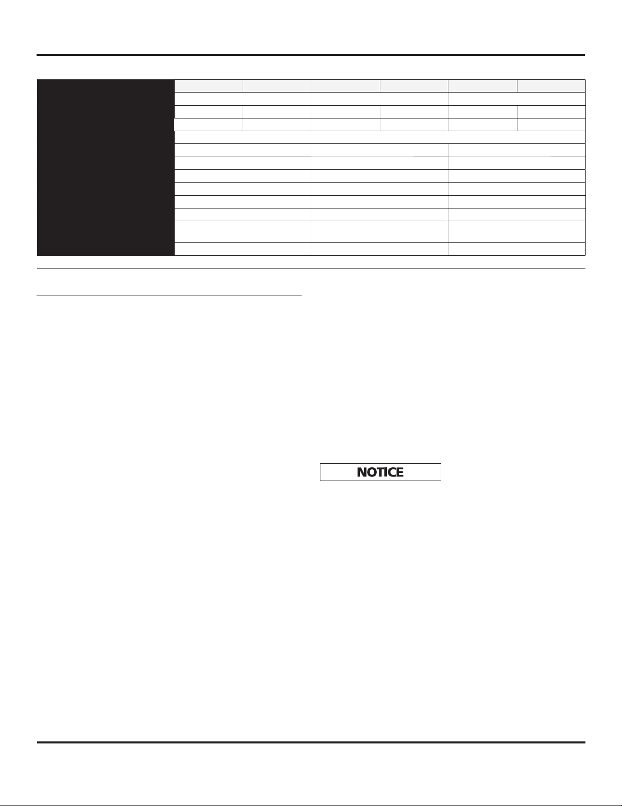
Compressor Specifi cations
Model SES02 SES12 SES03 SES13 SES05 SES15
HP 235
Phase 3Ø 1Ø 3Ø 1Ø 3Ø 1Ø
Voltage 208 - 230 / 460 / 575 230 208 - 230 / 460 / 575 230 208 - 230 / 460 / 575 230
Amps See wiring diagram for amp rating
Air End SLAE03EB SLAE03EB SLAE05E (SLAE05EHP)
Control System Pressure Switch Pressure Switch Pressure Switch
Discharge Pressure (PSIG) 95 - 115 (115 - 145 optional) 95 - 115 (115 - 145 optional) 95 - 115 (115 - 145 optional)
Air Delivery (CFM) 6.0 @ 100 PSIG and (4.6 @ 145 PSIG) 8.8 @ 100 PSIG and (7.1 @ 145 PSIG) 15.2 @ 100 PSIG and (12.5 @ 145 PSIG)
Compressor Speed (RPM) 2200 (1850) 3140 (2770) 3250 (3250)
Discharge Temp. Ambient temp. + 30 °F Ambient temp. + 30 °F Ambient temp. + 30 °F
Noise level dB(A)
[1.5m from front]
Dimensions In Inches (L x W x H) 34 x 21 x 32.5 34 x 21 x 32.5 34 x 21 x 32.5
49 49 51
(Items in paranthesis high pressure information)
Installation (Continued)
5. If necessary, use metal shims or leveling pads to level the
compressor. Never use wood to shim the compressor.
6. Never install the compressor outside.
7. For 3 and 5 HP single phase models it is recommended
that additional tank volume be added. 3 HP single phase
models need a minimum of 30 gallons air capacity to limit
the number of starts-per-hour to 14 maximum. 5 HP single
phase models need a minimum of 60 gallons air capacity
to limit the number of starts-per-hour to 10 maximum.
VENTILATION
1. If the scroll compressor is located in a totally enclosed
room, an exhaust fan with access to outside air must be
installed.
2. Never restrict the cooling fan exhaust air.
3. Vent the exhaust air outside to prevent the compressor
from operating at high temperatures and shutting down.
4. Never locate the compressor where hot exhaust air from
other heat generating units may be pulled into the unit.
WIRING
All electrical connections must be performed by a qualifi ed
electrician. Installations must be in accordance with local and
national electrical codes.
1. Make sure power source is the same voltage as the unit’s
required voltage
2. Use solderless terminals to connect the electric power
source.
3. Remove the two left panels.
4. Pull the electric cable through the electric source inlet and
connect to the primary side of the contact blocks.
5. Since loosening of wires is possible in shipment, tighten
all wire terminals prior to starting the unit.
PIPING
General Guidelines
1. Make sure the piping is lined up without being strained
or twisted when assembling the piping for the scroll
compressor.
2. Appropriate expansion loops or bends should be installed
at the compressor to avoid stresses caused by changes in
hot and cold conditions.
3. Piping supports should be anchored separately from the
compressor to reduce noise and vibration.
4. Never use any piping smaller than the compressor
connection.
5. Use fl exible hose to connect the outlet of the compressor
to the piping so that the vibration of the compressor does
not transfer to the piping.
Remote Intake Piping
Powerex Compressor Systems with pipe thread connectors on
the intake fi lters are intended for installation with remote air
intake. Piping for the remote intake system must be installed
at the fi nal operating site.
Under some conditions, the intake piping may facilitate the
condensation of humidity in the intake air stream into liquid
water.
The intake fi lters supplied by
Powerex will not stop ingestion
of liquid water by the pumps. Liquid water going into the
pumps will damage the pumps and void the warranty.
Always install drip legs with suffi cient capacity to capture
liquid water in the intake piping before the air fi lters. Drip
legs must be sized with low enough air velocity to make sure
they are effective at capturing liquid water in the intake air
and must be maintained (drained) at frequent intervals to
make sure they remain effective.
SAFETY VALVES
Tank mounted compressors are shipped from the factory with
safety valves installed in the air receiver manifold. The fl ow
capacity of the safety valve is equal to or greater than the
capacity of the compressor.
1. The pressure setting of the safety valve must be equal
or less than the maximum working pressure of the air
receiver.
2. Safety valves should be placed ahead of any possible
blockage point in the system, i.e. shutoff valve.
3. Avoid connecting the safety valve with any tubing or
piping.
4. Manually operate the safety valve every six months to
avoid sticking or freezing.
2
Page 3
2 HP - 5 HP Scroll Enclosure Air Compressors
Operation
BEFORE START UP
1. Make sure all safety warnings, labels and instructions have
been read and understood before continuing.
2. Remove any shipping materials, brackets, etc.
3. Confi rm that the electric power source and ground have
been fi rmly connected.
4. Check the belts for tightness.
5. Be sure all pressure connections are tight.
6. Check to be certain all safety relief valves, etc., are
correctly installed.
7. Securely mount all panels and guards.
8. Check that all fuses, circuit breakers, etc., are the proper
size.
9. Make sure the inlet fi lter is properly installed.
10. Confi rm that the drain valve is closed.
START-UP AND OPERATION
1. Visually check the rotation of the compressor pump.
The rotation should be counterclockwise if viewing the
compressor from the belt side. If the rotation is incorrect,
have a qualifi ed electrician correct the supply wiring.
2. Follow all the procedures under “Before start-up” before
attempting operation of the compressor.
3. Make sure compressor switch is in the OFF position.
4. Switch the electric source breaker on.
5. Open the 3/8 inch discharge valve completely.
6. Turn compressor switch to ON position and check that the
compressor operates without excessive vibration, unusual
noises or leaks.
7. Close the discharge valve completely.
8. If the pressure does not rise on a three phase unit, turn
the unit off. Have a qualifi ed electrician switch the
breaker OFF and exchange the L1 and L2 connections
(two out of three phases of electric source) on the control
panel.
9. Check the discharge pressure. Also make sure the air
pressure rises to the designated pressure setting by
checking the discharge pressure gauge.
10. Check the operation of the pressure switch by opening
the outlet valve and confi rming the compressor starts at
approximately 95 psig for low pressure units and 115 psig
or high pressure units.
DAILY OPERATION
1. Stop the compressor by turning switch to the OFF
position.
NOTE: If the compressor rotates in reverse for more than fi ve
seconds, the check valve needs to be cleaned or replaced.
2. Switch the breaker OFF if the compressor is not to be used
for a long period of time.
STOPPING THE COMPRESSOR DURING
NORMAL OPERATION
1. Close the discharge valve.
2. Allow the air pressure to build and the compressor to
stop.
3. Turn the compressor off by turning switch to the OFF
position.
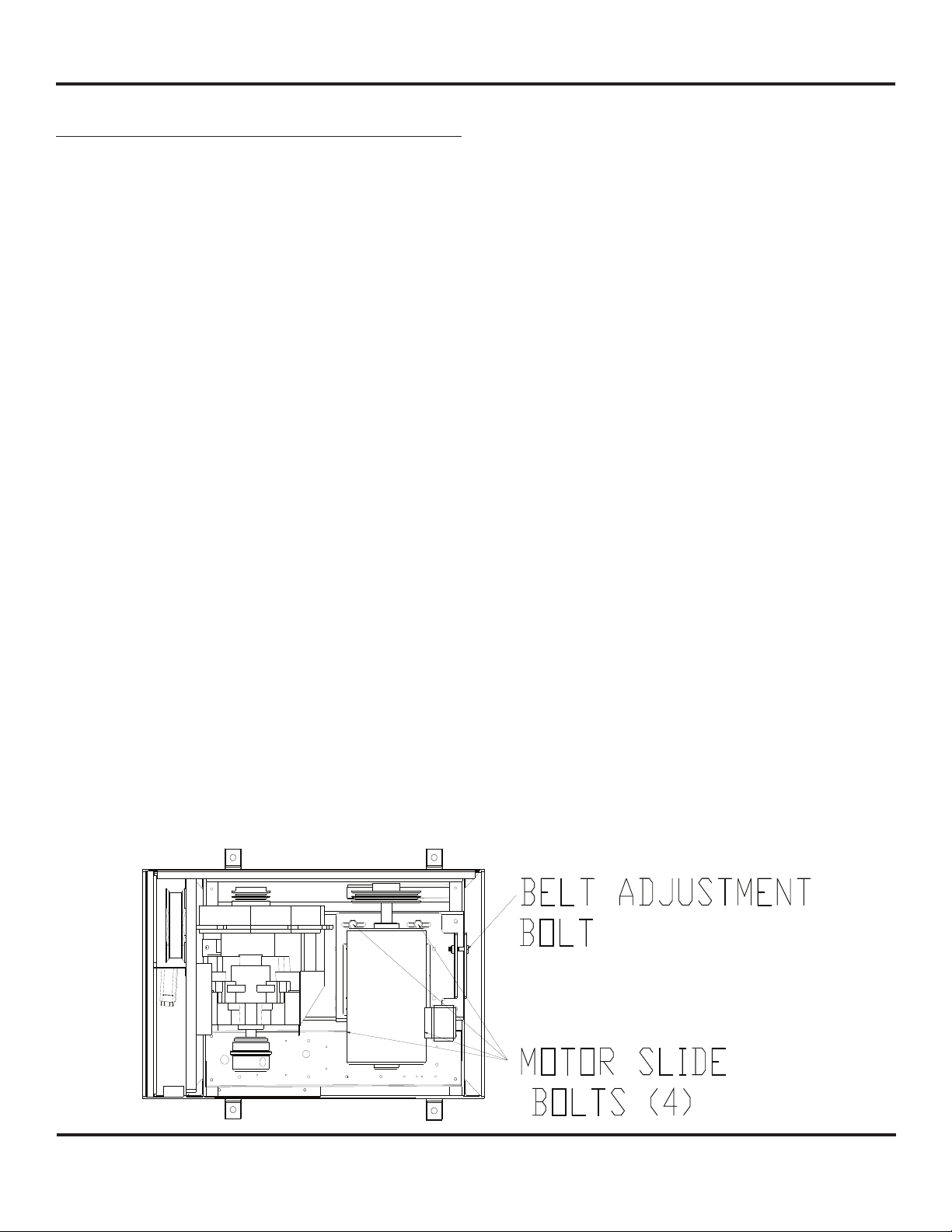
BELT ADJUSTMENT PROCEDURE
1. Remove the top panel by removing the two slotted 1/4-20
screws on the rear of the enclosure.
2. Loosen the four (4) motor slide bolts.
3. Tighten belt by adjusting the belt adjustment bolt. Belt
tension for new belts should be 57 to 65 lbs for the
loosest belt in the set, then 45-50 lbs after run-in. If the
belt tension falls below 25 lbs or chirping is heard as start
up, re-tension belts. (If using the defl ection method for
belt tension, 3.8-4.3 lbs force at mid span should give 7/32
inch belt defl ection for a new belt, 3.0-3.38 for a used belt
for 7/32 inch belt defl ection.
4. Tighten the four (4) motor slide bolts. Tighten the two
electrical panel side slide bolts fi rst then tighten the two
pulley side slide bolts.
Figure 1
3
Page 4
2 HP - 5 HP Scroll Enclosure Air Compressors
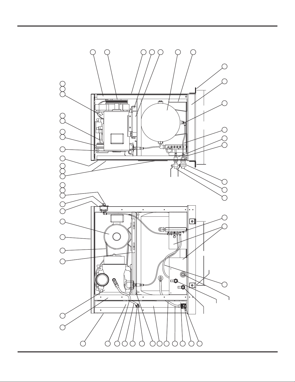
Scroll Unit Parts Breakdown -
Models SES02, SES12, SES03, SES13, SES05, SES15, SF120_PHA, and SF130_PHA
4950 51
37 38
16 17
101112
52
2829 3031
15
18
5
14
13
2
8
3
2021 22
23.15
2625
4
35
7
40 41 42 43
1
20.00
4 X DIA 0.50
32 33 34
27
8
39
MAIN POWER
INLET
3/8 INCH FNPT
AIR OUTLET
Figure 2
1/4 INCH FNPT
6
9
19
44
23
24
47
19
534546
54
TANK DRAIN
36
4
Page 5

2 HP - 5 HP Scroll Enclosure Air Compressors
Ref. No. Description SES02 / SES12 SES03 / SES13 SES05 / SES15 Qty.
1 Air end
(low pressure) SL014003AJ SL014003AJ SL016502AJ 1
(high pressure) SL014003AJ SL014003AJ SL016511AJ 1
2 13 gallon tank AR234800WH AR234800WH AR234800WH 1
3 Unit base SL303600AV SL303600AV SL303600AV 1
4 Front panel SL304500AV SL304500AV SL304500AV 1
5 Right panel SL304400AV SL304400AV SL304400AV 1
6 Back panel SL304600AV SL304600AV SL304600AV 1
7 Top panel SL304800AV SL304800AV SL304800AV 1
8 Utility panel SL305200AV SL305200AV SL305200AV 3
9 Internal duct SL304901AV SL304901AV SL304901AV 1
10 Left panel SL304300AV SL304300AV SL304300AV 1
11 Maintenance panel 1 SL305000AV SL305000AV SL305000AV 1
12 Inside panel SL304700AV SL304700AV SL304700AV 1
13 Pump base SL304101AV SL304101AV SL304101AV 1
14 Mounting foot IP630300AV IP630300AV IP630300AV 4
15 “H” support SL305100AV SL305100AV SL305100AV 2
16 Inlet fi lter assembly ST073925AV ST073925AV ST073925AV 1
17 Filter element ST073921AV ST073921AV ST073921AV 1
18 Motor pulley
2HP (low pressure, 2-3V4.45) 3Ø PU202633AV - - 1
1Ø PU202623AV
2HP (high pressure, 2-3V3.65) 3Ø PU202632AV - - 1
1Ø PU202622AV
3HP (low pressure, 2-3V6.0) - PU202625AV - 1
3HP (high pressure, 2-3V5.3) - PU202624AV - 1
5HP (low pressure, 2-3V6.9) - - PU009754AV 1
5HP (high pressure, 2-3V6.9) - - PU009754AV 1
20 1/4 T x 1/4 P x 90˚ push connect ST119702AV ST119702AV ST119702AV 1
21 1/4 inch drain tube PS010300AV PS010300AV PS010300AV 2.0 ft.
22 Corner angle ST185500AV ST185500AV ST185500AV 4
23 Temperature switch @ 115 psi AM003011AV AM003011AV AM003011AV 1
Temperature switch @ 145 psi AM003012AV AM003012AV AM003012AV 1
24 Sub panel SL305300AV SL305300AV SL305300AV 1
25 1/4 inch bulk head fi tting PS006701AV PS006701AV PS006701AV 1
26 3/8 inch bulk head fi tting PS006702AV PS006702AV PS006702AV 1
27 Safety valve
(Low pressure unit) V-215100AV V-215100AV V-215100AV 1
(High pressure unit) V-215401AV V-215401AV V-215401AV 1
28 Maintenance panel 2 SL306500AV SL306500AV SL306500AV 1
29 Motor slide base SL306701AV SL306701AV SL306701AV 1
30 Pressure switch
(Low pressure unit) CW207573AV CW207573AV CW207573AV 1
(High pressure unit) CW207595AV CW207595AV CW207595AV 1
31 Lighted off/on switch PE000560AV PE000560AV PE000560AV 1
32 3/8 inch ball valve ST079802AV ST079802AV ST079802AV 1
33 1/4 inch ball valve ST079806AV ST079806AV ST079806AV 1
34 Electrical strain relief ST188106AV ST188106AV ST188106AV 1
35 Motor
2hp 1 phase MC301579AV - - 1
2hp 3 phase MC303300AV - - 1
3hp 1 phase - MC301579AV - 1
3hp 3 phase (208 - 230 / 460 V) - MC303301AV - 1
3hp 3 phase (575 V) - MC303302AV - 1
5hp 1 phase - - MC022393AV 1
5hp 3 phase (208 - 230 / 460 V) - - MC303303AV 1
5hp 3 phase (575 V) - - MC303304AV 1
5
Page 6

2 HP - 5 HP Scroll Enclosure Air Compressors
Scroll Unit Parts Breakdown -
Models SES02, SES12, SES03, SES13, SES05, SES15, SF120_PHA, and SF130_PHA
4950 51
37 38
16 17
101112
52
2829 3031
15
18
5
14
13
2
8
3
2021 22
23.15
2625
4
35
7
40 41 42 43
1
20.00
4 X DIA 0.50
32 33 34
27
8
39
MAIN POWER
INLET
3/8 INCH FNPT
AIR OUTLET
Figure 2 (Continued)
1/4 INCH FNPT
6
9
19
44
23
24
47
19
534546
54
TANK DRAIN
36
6
Page 7

2 HP - 5 HP Scroll Enclosure Air Compressors
Ref. No. Description SES02 / SES12 SES03 / SES13 SES05 / SES15 Qty.
36 Check valve IP087700AV IP087700AV IP087700AV 1
37 Fan IP632400AV IP632400AV IP632400AV 1
38 Fan guard IP632401AV IP632401AV IP632401AV 1
39 3/8 inch PTFE tube PS001800AV PS001800AV PS001800AV 2.5 ft.
40 Belt
2hp low pressure BT009001AV - - 2
2hp high pressure BT009001AV - - 2
3hp low pressure - BT013800AV - 2
3hp high pressure - BT012001AV - 2
5hp low/high pressure - - BT010701AV 2
41 High temp light PE000538AV PE000538AV PE000538AV 1
42 Unit pressure gauge IP632603AV IP632603AV IP632603AV 1
43 Hourmeter PE001004AV PE001004AV PE001004AV 1
44 Jic fi tting ST186422AV ST186422AV ST186422AV 1
45 Braided hose SM001502AV SM001502AV SM001502AV 1
46 Rubber mounting block AG007501AV AG007501AV AG007501AV 3
47 After cooler SL300101AV SL300101AV SL300101AV 1
◆
48
49 Fan cord IP632800AV IP632800AV IP632800AV 1
50 Intake adaptor plate IP088400AV IP088400AV IP088400AV 1
51 Adaptor plate gasket IP088200AV IP088200AV IP088200AV 1
52 1/4 - 20 screw ST074003AV ST074003AV ST074003AV 8
53 3/8 inch PTFE tube PS001800AV PS001800AV PS001800AV 1 ft.
54 3/8 x 3/8 x 90 push connect ST119705AV ST119705AV ST119705AV 2
Parts unique to: SF120_PHA SF130_PHA
3 Deep base SL305401AV SL305401AV – 1
18 Motor pulley (50 Hz) PU202623AV PU202626AV – 1
35 Motor (60 Hz) MC301594AV MC301594AV – 1
40 Belt (50 Hz) BT012001AV BT010701AV – 2
42 Unit Pressure Gauge GA032201AV GA032201AV – 1
Parts unique to: SF1309
16 Inlet fi lter assembly – ST072925AV – 2
17 Filter element – ST073921AV – 2
23 Temperature switch – AM003017AV – 2
30 Pressure switch (low pressure
35 Motor (60 Hz) – MC022309AV – 1
44 Jic fi tting (aftercooler side) – ST186402AV – 1
45 Braided hose – SM001504AV – 1
◆
Cabinet screw ST129304AV ST129304AV ST129304AV 32
Motor (50 Hz) MC301578AV MC301578AV – 1
◆
Swivel caster ST187901AV ST187901AV – 4
– CW207560AV – 1
unit)
Jic fi tting (pump side) – ST186419AV – 1
= Not shown
7
Page 8

2 HP - 5 HP Scroll Enclosure Air Compressors
Maintenance Schedule (see Pump Manual for “How To” Instructions)
Operating Hours
Item Action needed 500 2500 5000 10,000 20,000 Remarks
Receiver Drain moisture Daily
Cartridge Filter Clean, Replace
Ventilation Screen Clean
Blower Fan Clean
Fan Duct Clean
Compressor Fins Clean
Compressor Regrease
Tip Seal Set Replace
Heat Insulation Pipe Replace
V-belt Inspect, Replace
●▲
●
Readjust
●
●
●
●
▲
(Every 5000
hours for
145 psig
units)
▲
(Every 5000
hours for
145 psig
units)
▲
(Every 5000
hours for
145 psig
units)
▲▲▲
▲▲
▲▲
▲▲
If equiped with an
Electric Drain, test daily
Part # ST073921AV
Use genuine Powerex
grease
Temperature Sensor Confi rm operation
Pressure Switch Confi rm operation
Magnetic Starter Inspect
Safety Valve Confi rm operation
Pressure Gauge Inspect
Ventilation Fan Inspect
●
●
●
●
●
●
Replace if contact point is
deteriorated
Replace if malfunctions
● Inspect
▲ Replace
Notes:
1. Inspect and perform maintenance periodically according to maintenance schedule.
2. The maintenance schedule relates to the normal operating conditions. If the circumstances and load condition
are adverse, shorten the interval time and perform maintenance accordingly.
3. Marked “Readjust” means the tension of the V-belt should be adjusted during the initial stage and inspected every 2,500
hours afterwards; 57-65 lbs initially, then 45-50 lbs after run-in.
8
Page 9

2 HP - 5 HP Scroll Enclosure Air Compressors
Maintenance Log
Date Maintenance Required Maintenance Performed
9
Page 10

2 HP - 5 HP Scroll Enclosure Air Compressors
Electrical Diagram - Single Phase Units 230 Volts
Figure 3
10
Page 11

2 HP - 5 HP Scroll Enclosure Air Compressors
Electrical Diagram - Three Phase Units 208 - 230 - 460 - 575 Volts
Figure 4
11
Page 12

2 HP - 5 HP Scroll Enclosure Air Compressors
5
PS1
Figure 5
2
4
TR1
3
6
CR1
MSX
L3
L2
L1
OLX
GND
GND
DK699800AJ
1
Scroll Electrical Panel Replacement Parts
Key # 1234 5 6
Motor Starter /
Model HP 115 PSI 145 PSI
SES02082
208V,3P
SES02083
230V,3P
SES02084
460V,3P
SES12086
230V, 1P
SES03082
208V,3P
SES03083
230V,3P
SES03084
460V,3P
SES03085
575V,3P
SES13086
230V,1P
SF13087
230V, 1P
SF13085
230V, 1P
SF13097
230V, 1P
SF13095
230V, 1P
SES05082
208V,3P
SES05083
230V,3P
SES05084
460V,3P
SES05085
575V,3P
SES15086
230V,1P
Overload Relay
PE000101AV /
PE000205AV
PE000102AV /
PE000210AV
2
PE000101AV /
PE000204AV
PE000103AV /
PE000207AV
PE000102AV /
PE000206AV
PE000102AV /
PE000210AV
PE000101AV /
PE000204AV
PE000101AV /
PE000203AV
PE000103AV /
3
PE000207AV
PE000102AV /
PE000207AV
PE000102AV /
PE000207AV
PE000103AV /
PE000208AV
PE000102AV /
PE000207AV
PE000102AV /
PE000207AV
PE000102AV /
PE000207AV
PE000101AV /
5
PE000205AV
PE000101AV /
PE000204AV
PE000104AV /
PE000209AV
Control
Transformer
Fuse 1 / Fuse 2
(2 REQUIRED)
PS005834AV JP007716AV
PS005834AV JP007716AV
PS005834AV JP007702AV
PS005834AV JP007716AV
PS005834AV JP007716AV
PS005834AV JP007716AV
PS005834AV JP007702AV
PS005847AV JP007702AV
PS005834AV JP007716AV
JP007716AV
JP007716AV
PS005834AV
JP007716AV
JP007716AV
PS005834AV JP007716AV
PS005834AV JP007716AV
PS005834AV JP007702AV
PS005847AV JP007702AV
PS005834AV JP007716AV
Fuse 3
JP007711AV
Pressure Switch
CW207573AV
CW207560AV
CW207573AV
Control
Relay
CW207595AV PE000403AV
12
Page 13

2 HP - 5 HP Scroll Enclosure Air Compressors
Troubleshooting Guide
PROBLEM CAUSE CORRECTIVE ACTION
Power ON light does not
appear
Power ON light is on but unit
will not start
Compressor is running but will
not make pressure
Excessive noise or vibration 1. Drive belt has separated or fl at spot
Compressor shuts down on
high temperature
Compressor turns on / off
rapidly
Safety valves blows off 1. Pressure switch has failed to open
Motor Overload has tripped 1. Pump has failed
1. Main disconnect is not ON
2. Blown fuse or circuit breaker at
customer provided power supply
3. Blown fuse at transformer
4. Lighted switch is burned out
1. Motor overload has tripped
2. Wrong or low voltage
3. Starter has failed
4. Motor has failed
1. Drive belts came off or too loose
2. Clogged intake fi lter element
3. Pressure relief valve has opened
4. Excessive tip seal wear
5. Electric tank drain is open continuously
6. Unit running in the wrong direction
7. Discharge air is leaking
2. Motor has failed
3. Pump is damaged
4. Cooling air fan is touching fan guard
1. Room temperature is above 104° F
2. Inlet air duct is obstructed
3. Cooling air fan not running
4. Aftercooler fi ns clogged
5. Intake fi lter damaged
6. Compressor is dirty
7. Tip seals worn
1. Receiver tank has high level of water
2. Compressor check valve has failed
3. Defective pressure switch
2. Motor starter contacts welded shut
2. Motor has failed
3. Improper wiring
4. Wrong overload setting
5. Low voltage
1. Switch disconnect to ON
2. Inspect for any fault replace fuse or trip
disconnect to ON
3. Replace fuse - be sure to use same type and
size
4. Replace lighted switch
1. See last entry of Troubleshooting Guide
2. Check incoming power supply and unit power
rating
3. Replace contactor assembly
4. Replace motor
1. Replace drive belts and (or) tighten
2. Replace intake fi lter element
3. Pressure switch needs replaced or motor
contacts welded shut
4. Replace tip seals
5. Replace tank drain
6. Correct power connections
7. Check discharge piping
1. Replace drive belt
2. Replace motor
3. Fix or replace pump
4. Check air fan daily
1. Add ventilation or air conditioning to room
2. Remove obstruction or reposition unit to allow
for cooling air
3. Replace cooling air fan
4. Clean aftercooler
5. Check intake fi lter
6. Clean unit
7. Replace tip seals
1. Replace electric tank drain / drain tank
2. Replace check valve
3. Replace pressure switch
1. Replace pressure switch
2. Replace motor starter
1. Fix or replace pump
2. Replace motor
3. Check wiring
4. Check overload setting
5. Check incoming power supply
13
Page 14

2 HP - 5 HP Scroll Enclosure Air Compressors
Notes
14
Page 15

2 HP - 5 HP Scroll Enclosure Air Compressors
Powerex Limited Warranty – Applicable to Non-OEM Customers in the U.S. & Canada Only
Warranty and Remedies.
(a) General. Powerex warrants each Compressor System, Vacuum System, Vacuum Pump, Compressor Air-End, or Powerex branded Accessory
(collectively “Products”, individually each a “Product”) to be free from defects in material and workmanship (“Defects”) at the date of
shipment. This warranty shall apply only to Products that are purchased and used in the United States of America and in Canada. EXCEPT AS
SET FORTH BELOW, NO OTHER WARRANTY, WHETHER EXPRESS OR IMPLIED, INCLUDING ANYWARRANTY OF MERCHANTABILITY OR FITNESS
FOR A PARTICULAR PURPOSE, SHALL EXIST IN CONNECTION WITH THE SALE OR USE OF SUCH PRODUCTS. TO THE EXTENT PERMITTED BY LAW,
ANY AND ALL IMPLIED WARRANTIES ARE EXCLUDED. All warranty claims must be made in writing and delivered to Powerex in accordance
with the procedures set forth on its website (www.powerexinc.com), or such claim shall be barred. Upon timely receipt of a warranty claim,
Powerex shall inspect the Product claimed to have a Defect, and Powerex shall repair, or, at its option, replace, free of charge, any Product
which it determines to have had a Defect; provided, however, that if circumstances are such as to preclude the remedying of Defect by repair
or replacement, Powerex shall, upon return of the Product, refund to buyer any part of the purchase price of such Products paid to Powerex.
Freight for returning Products to Powerex for inspection shall be paid by buyer. The warranties and remedies herein are the sole and exclusive
remedy for any breach of warranty or for any other claim based on any Defect, or non-performance of the Products, whether based upon
contract, warranty or negligence.
(b) (i) Standard Period of Warranty – Parts and Labor - The purchase of any system includes our standard warranty. Powerex warrants
and represents all Products shall be free from Defects for the fi rst eighteen (18) months from the date of shipment by Powerex, or twelve
(12) months from the documented date of startup, or fi ve thousand (5,000) hours of use, whichever occurs fi rst. During such warranty period,
Powerex shall be fully liable for all Defects in the Products (the “Product Defects”), i.e., all costs of repair or replacement, which may include
“in and out” charges, so long as the Products are located in the United States or Canada, and the Products are reasonably located and
accessible by service personnel for removal. “In and out” charges include the costs of removing a Product from buyer’s equipment for repair or
replacement.
(ii) Premium Period of Warranty – Parts and Labor - In order to be eligible for premium warranty coverage, a premium warranty for
each system must be purchased when order is placed. Powerex warrants and represents all Products shall be free from Defects for the fi rst thirty
(30) months from the date of shipment by Powerex, or twenty-four (24) months from the documented date of startup, or seven thousand fi ve
hundred (7,500) hours of use, whichever occurs fi rst. During such warranty period, Powerex shall be fully liable for all Defects in the Products
(the “Product Defects”), i.e., all costs of repair or replacement, which may include “in and out” charges, so long as the Products are located in
the United States or Canada, and the Products are reasonably located and accessible by service personnel for removal. “In and out” charges
include the costs of removing a Product from buyer’s equipment for repair or replacement.
(c) Additional Period of Warranty – Parts Only (No Labor). In addition to the above, Powerex warrants each Powerex branded Compressor
Air- End and Vacuum Pump shall be free of Defects for a period of forty-two (42) months from the date of shipment by Powerex, or thirty-six
(36) months from the documented date of startup, or ten thousand (10,000) hours of use, whichever occurs fi rst. Supplier’s repair or replacement
of any Product shall not extend the period of any warranty of any Product. This warranty applies to the exchange of part(s) found to be
defective by an Authorized Powerex Service Representative only.
(d) Replacement Pumps – Parts Only (No Labor). For any replacement Air-End or Vacuum Pumps installed on a Powerex manufactured
system or unit after any initial warranty period has expired or where another warranty does not apply for any reason, Powerex warrants
that the Air-End or Vacuum Pumps shall be free of Defects for a period of thirty-six (36) months from the date of shipment by Powerex or
ten thousand (10,000)hours of use, whichever comes fi rst. For any replacement Air-End or Vacuum Pumps installed on a system that was not
manufactured by Powerex after any initial warranty period has expired or where another warranty does not apply for any reason, Powerex
warrants that the Air-End or Vacuum Pumps shall be free of Defects for the fi rst twelve (12) months from the date of shipment by Powerex.
Supplier’s repair or replacement of any Product shall not extend the period of any warranty of any Product. This warranty applies to the
exchange of part(s) found to be defective by an Authorized Powerex Service Representative only.
(e) Replacement Motors – Parts Only (No Labor). For any replacement motor installed on a Powerex manufactured system or unit after any
initial warranty period has expired or where another warranty does not apply for any reason, Powerex warrants that the replacement motor
shall be free of Defects for the fi rst twelve (12) months from the date of shipment by Powerex. For any replacement motor installed on a system
or unit that was not manufactured by Powerex after any initial warranty period has expired or where another warranty does not apply for
any reason, Powerex warrants that the replacement motor shall be free of Defects for the fi rst ninety (90) days from the date of shipment by
Powerex. Supplier’s repair or replacement of any Product shall not extend the period of any warranty of any Product. This warranty applies to
the exchange of part(s) found to be defective by an Authorized Powerex Service Representative only.
(f) Replacement Parts – Parts Only (No Labor). For other replacement parts besides motors, Air-End or Vacuum Pumps installed on a Powerex
manufactured system or unit after any initial warranty period has expired or where another warranty does not apply for any reason, Powerex
warrants that such replacement parts will be free from Defects for the fi rst twelve (12) months from the date of shipment by Powerex. For other
replacement parts besides motors, Air-End or Vacuum Pumps installed on a system or unit that was not manufactured by Powerex after any
initial warranty period has expired or where another warranty does not apply for any reason, Powerex makes no warranties. Supplier’s repair or
replacement of any Product shall not extend the period of any warranty of any Product. This warranty applies to the exchange of part(s) found
to be defective by an Authorized Powerex Service Representative only.
(g) Coverage. The warranty provided herein applies to Powerex manufactured units or systems only.
(h) Exceptions. Notwithstanding anything to the contrary herein, Powerex shall have no warranty obligations with respect to Products:
(i) that have not been installed in accordance with Powerex’s written specifi cations and instructions;
(ii) that have not been maintained in accordance with Powerex’s written instructions;
(iii) that have been materially modifi ed without the prior written approval of Powerex; or
(iv) that experience failures resulting from operation, either intentional or otherwise, in excess of rated capacities or in an otherwise
improper manner.
15
Page 16

2 HP - 5 HP Scroll Enclosure Air Compressors
(i) The warranty provided herein shall not apply to:
(i) any defects arising from corrosion, abrasion, use of insoluble lubricants, or negligent attendance to or faulty operation of the
Products;
(ii) ordinary wear and tear of the Products;
(iii) defects arising from abnormal conditions of temperature, dirt or corrosive matter; or
(iv) any OEM component which is shipped by Powerex with the original manufacturer’s warranty, which shall be the sole applicable
warranty for such component.
Limitation of Liability. NOTWITHSTANDING ANYTHING TO THE CONTRARY HEREIN, TO THE EXTENT ALLOWABLE UNDER APPLICABLE LAW,
UNDER NO CIRCUMSTANCES SHALL POWEREX BE LIABLE FOR ANY INCIDENTAL, CONSEQUENTAL, PUNITIVE, SPECULATIVE OR INDIRECT LOSSES
OR DAMAGES WHATSOEVER ARISING OUT OF OR IN ANY WAY RELATED TO ANY OF THE PRODUCTS OR GOODS SOLD OR AGREED TO BE SOLD
BY POWEREX TO BUYER. TO THE EXTENT ALLOWABLE UNDER APPLICABLE LAW, POWEREX’S LIABILITY IN ALL EVENTS IS LIMITED TO, AND
SHALL NOT EXCEED, THE PURCHASE PRICE PAID.
Warranty Disclaimer. Powerex has made a diligent effort to illustrate and describe the Products in its literature, including its Price
Book,accurately; however, such illustrations and descriptions are for the sole purpose of identifi cation, and do not express or imply a warranty
that the Products are merchantable, or fi t for a particular purpose, or that the Products will necessarily conform to the illustrations or
descriptions.
Product Suitability. Many jurisdictions have codes and regulations governing sales, construction, installation, and/or use of Products for certain
purposes, which may vary from those in neighboring areas. While Powerex attempts to assure that its Products comply with such codes, it cannot
guarantee compliance, and cannot be responsible for how the product is installed or used. Before purchase and use of a Product, please review
the Product applications, and national and local codes and regulations, and be sure that the Product, installation, and use will comply with
them.
Claims. Any non-warranty claims pertaining to the Products must be fi led with Powerex within 6 months of the invoice date, or they will not
be honored. Prices, discounts, and terms are subject to change without notice or as stipulated in specifi c Product quotations. Powerex shall
not be liable for any delay or failure arising out of acts of the public enemy, fi re, fl ood, or any disaster, labor trouble, riot or disorder, delay in
the supply of materials or any other cause, whether similar or dissimilar, beyond the control of Company. All shipments are carefully inspected
and counted before leaving the factory. Please inspect carefully any receipt of Products noting any discrepancy or damage on the carrier’s
freight bill at the time of delivery. Discrepancies or damage which obviously occurred in transit are the carrier’s responsibility and related claims
should be made promptly directly to the carrier. Returned Products will not be accepted without prior written authorization by Powerex and
deductions from invoices for shortage or damage claims will not be allowed. UNLESS OTHERWISE AGREED TO IN WRITING, THE TERMS
AND CONDITIONS CONTAINED IN THIS LIMITED WARRANTY WILL CONTROL IN ANY TRANSACTION WITH POWEREX. Any different or
confl icting terms as may appear on any order form now or later submitted by the buyer will not control. All orders are subject to acceptance by
Powerex.
Powerex • 150 Production Drive • Harrison, OH 45030 • USA
1-888-769-7979 • www.powerexinc.com
16
 Loading...