


Powerex SED1007, SED1007HP, SET1507, SET1507HP, SEQ2007 User Manual
...10HP - 20HP Scroll Enclosure Air Compressors
Please read and save these instructions. Read carefully before attempting to assemble, install, operate or maintain the product described. Protect yourself and others by observing all safety information. Failure to comply with instructions could result in personal injury and/or property damage! Retain instructions for future reference.
DESCRIPTION
GENERAL
Powerex Scroll Enclosure Air Compressors are designed to supply continuous oil-free air by using the most advanced scroll technology. These turn-key packages are extremely quiet and offer electronic control that will reduce electrical power consumption.
The Powerex Oil-less Rotary Scroll Air Compressor has advanced scroll compressor technology through the development of a completely oil-less unit. The Powerex Scroll Compressor offers a dynamically balanced air end which insures vibration-free operation. The rotary design permits a continuous 100% duty cycle. No oil separation, oil filtration, or inlet valves are required on the Powerex Scroll unit. The compressor is virtually maintenance free.
The Powerex Oil-less Rotary Scroll Air Compressor is based on the theory of scroll compression. A scroll is a free standing, intricate spiral bounded on one side by a solid, flat plane or base. A scroll set, the basic compression element of a scroll compressor, is made up of two identical spirals which form right and left hand parts. One of these scroll components is indexed or phased 180° with respect to the other so the scrolls can mesh. Crescent-shaped gas pockets are formed and bounded by the spirals and the base plate of both scrolls. As the moving scroll is orbited around the fixed scroll, the pockets formed by the meshed scrolls follow the spiral toward the center and diminish in size. The moving scroll is prevented from rotating during this process so the 180° phase relationship of the scrolls is maintained. The compressor’s inlet is at the outer boundary of the scrolls. The entering gas is trapped in two completely opposite gas pockets and compressed as the pockets move toward the center. The compressed gas is discharged through the outlet at the center of the fixed scroll so no valves are needed.
Table of Contents
Specifications |
Pg 1–2 |
Maintenance |
Pg 12 |
Safety Guidelines |
Pg 2-3 |
Electrical |
Pg 13-15 |
Installation |
Pg 3-7 |
|
|
Operation |
Pg 8-11 |
|
|
Powerex - 150 Production Drive - Harrison, Ohio 45030 - USA 1-888-769-7979 - www.powerexinc.com
SPECIFICATIONS
Product |
SE Series Enclosed Scroll Air |
|
Compressor |
|
|
Performance |
See page 2 |
Specifications |
|
|
|
Lubrication |
Grease-filled Bearing |
|
|
Operating |
3Ø - 208-230/460/575 Volts, 60 Hz |
Voltages |
|
|
|
Compression |
Scroll |
Cycle |
|
|
|
Motor Overload |
Motor Protector/Circuit Breaker |
Protection |
|
|
|
Pressure Settings |
Cut in: 90 psig Cut out: 116 psig |
|
Cut in: 119 psig Cut out: 145 psig |
|
(High Pressure Units) |
|
|
Overpressure |
Safety Valve Factory Set and Sealed |
Protection |
|
|
|
Outlet Air |
See page 2 |
Connections |
|
|
|
Tank Sizes |
See Page 6, Chart 2 |
|
|
Drive |
3V Belt |
|
|
Agency Approvals |
UL/CSA Certified |
|
|
Pg 1
IN562802AV 04/13
10 HP - 20 HP Scroll Enclosure Air Compressors
SPECIFICATION CHART
Model |
HP |
Max |
SCFM @ |
Voltage |
Noise |
Discharge |
LxWxH |
Weight |
Discharge |
|
|
Pressure |
Max |
|
Level |
Connection |
(inches) |
(lbs.) |
Air |
|
|
PSIG |
Pressure |
|
dB(A) |
|
|
|
Approach |
|
|
|
|
|
|
|
|
|
Temp |
SED1007 |
10 |
116 |
30.4 |
208/230/460/575 |
53 |
1 Inch |
38 x 26 x 61 |
825 |
67°F |
|
|
|
|
|
|
|
|
|
|
SED1007HP |
10 |
145 |
25 |
208/230/460/575 |
53 |
1 Inch |
38 x 26 x 61 |
825 |
80°F |
|
|
|
|
|
|
|
|
|
|
SET1507 |
15 |
116 |
45.6 |
208/230/460/575 |
56 |
1 Inch |
38 x 26 x 61 |
965 |
67°F |
|
|
|
|
|
|
|
|
|
|
SET1507HP |
15 |
145 |
37.5 |
208/230/460/575 |
56 |
1 Inch |
38 x 26 x 61 |
965 |
80°F |
|
|
|
|
|
|
|
|
|
|
SEQ2007 |
20 |
116 |
60.8 |
208/230/460/575 |
58 |
1 Inch |
38 x 26 x 61 |
1125 |
67°F |
|
|
|
|
|
|
|
|
|
|
SEQ2007HP |
20 |
145 |
50 |
208/230/460/575 |
58 |
1 Inch |
38 x 26 x 61 |
1125 |
80°F |
|
|
|
|
|
|
|
|
|
|
SAFETY GUIDELINES
This manual contains information that is very important to know and understand. This information is provided for SAFETY and to PREVENT EQUIPMENT PROBLEMS. To help recognize this information, observe the following symbols. MAKE SURE EVERYONE OPERATING OR SERVICING THE COMPRESSOR READS AND UNDERSTANDS ALL THE INFORMATION PROVIDED.
Danger indicates and imminently hazardous situation which, if not avoided, WILL result in death or injury.
Warning indicates a potentially hazardous situation which, if not avoided, COULD result in death or serious injury.
Caution indicates a potentially minor or moderate injury.
Notice indicates important information, that if not
followed, may cause damage to equipment.
GENERAL SAFETY INFORMATION
Since the air compressor makes up a high pressure system, the following safety precautions must be observed at all times.
1.Read all manuals included with this product carefully. Be thoroughly familiar with the controls and the proper use of the equipment.
2.Follow all local electrical and safety codes as well as in the United States, the National
Electrical Codes (NEC) and Occupational Safety and Health Act (OSHA).
3.Only persons well acquainted with these rules of safe operation should be allowed to use the compressor.
4.Keep visitors away and NEVER allow children in the work area.
Pg 2
5.Wear safety glasses and use hearing protection when operating the unit.
6.Do not stand on or use the unit as a handhold.
7.Before each use, inspect compressed
air system and electrical components for signs of damage, deterioration, weakness or leakage. Repair or replace defective items before using.
8.Check all fasteners at frequent intervals for proper tightness.
Motors, electrical
equipment and controls can cause electrical arcs that will ignite a flammable gas or vapor. Never operate or repair in or near a
flammable gas or vapor. Never store flammable liquids or gases in the vicinity of the unit.
Never operate compressor pump without a protective guard. This unit can start automatically without warning. Personal injury or property damage could occur from contact with moving parts.
BREATHABLE AIR
WARNING
This unit is NOT equipped and should NOT be used “as is” to supply breathing quality air. For any application of air for human consumption, you must fit the air compressor with suitable in-line safety and alarm equipment. This additional equipment is necessary to properly filter and purify the air to meet minimal specifications for Grade D breathing as described in Compressed Gas Association Commodity Specification for Air, OSHA, ANSI and/or Canadian Standards Associations (CSA).
DISCLAIMER OF WARRANTIES
IN THE EVENT THE COMPRESSOR IS USED FOR THE PURPOSE OF BREATHING AIR APPLICATION AND PROPER IN-LINE SAFETY AND ALARM EQUIPMENT IS NOT SIMUTANEOUSLY USED, EXISTING WARRANTIES ARE VOID, AND POWEREX DISCLAIMS ANY LIABILITY WHATSOEVER FOR ANY LOSS, PERSONAL INJURY OR DAMAGE.
10 HP - 20 HP Scroll Enclosure Air Compressors
GENERAL SAFETY CONT.
9.Do not wear loose clothing or jewelry that will get caught in the moving parts of the unit.
Surface may be hot even if unit is stopped.
10.Keep fingers away from a running unit;
fast moving and hot parts will cause injury and/or burns.
11.If the equipment should start to vibrate abnormally, STOP the unit and check immediately for the cause. Vibration is generally a warning of trouble.
12.To reduce fire hazard, keep unit exterior free of oil, solvent, or excessive grease.
An ASME code safety relief valve with a setting no higher than the tank maximum allowable working pressure MUST be installed in the air lines or in the tank of any compressor. The ASME safety valve must have sufficient flow and pressure ratings to protect the pressurized components from bursting.
Do not operate with pressure switch or pilot valves set higher
than the tank maximum allowable working pressure.
13.Never attempt to adjust ASME safety valve on compressed air units. Keep safety valve free from paint and other accumulations.
Never attempt to repair or modify a tank! Welding, drilling or any other modification will weaken the tank resulting in damage
from rupture or explosion. Always replace worn, cracked or damaged tanks.
 Drain liquid from tank daily.
14.Tanks rust from moisture build-up, which weakens the tank. Make sure to drain tank regularly and inspect periodically for unsafe conditions such as rust formation and corrosion.
15.Fast moving air will stir up dust and debris which may be harmful. Release air slowly when draining moisture or depressurizing a compressor system.
STORAGE
1.When not in use, the unit should be covered to prevent the ingress of dirt and foreign matter and stored in a cool, dry place.
2.If a tank is incorporated with the unit, the tank should be drained of all moisture.
3.If the unit is using external hoses, they should be disconnected and hung open ends down to allow any moisture to drain.
INSTALLATION
Disconnect, tag and lock out power source then release all pressure from the system before attempting to install, service, relocate or perform any maintenance.
Do not lift or move unit without appropriately rated equipment.
Be sure the unit is securely attached to lifting device used. Do not lift unit by holding on to tubes or coolers. Do not use unit to lift other attached equipment.
Never use the wood shipping skids for mounting the unit.
Do not locate the air inlet near steam, paint spray, sandblast
areas or any other source of contamination.
NOTE: If compressor system is installed in a hot, moist environment, supply compressor pump with clean, dry outside air. Pipe supply air in from external sources.
Failure to properly install a tank can lead to cracks at the welded joints and possible bursting or leakage.
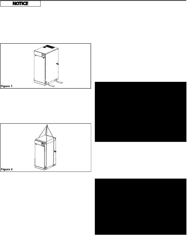
UNPACKING
After unpacking the unit, inspect carefully for any damage that may have occurred during transit. Make sure to tighten fittings, bolts, etc., before putting unit into service.
Do not operate unit if damaged during shipping, handling or
use. Damage may result in bursting and cause injury or property damage.
The compressor nameplate should be checked to see if the unit is the correct model and voltage as ordered.
Pg 3
10 HP - 20 HP Scroll Enclosure Air Compressors
INSTALLATION CONT.
PRECAUTIONS DURING TRANSPORTATION AND MOVEMENT
TRANSPORTATION BY FORKLIFT
Use openings for forklift under both sides of the unit.
Avoid damaging the panel with tips of forklift.
TRANSPORTATION BY CRANE
Use openings at bottom of the unit to life up by cable, lifting straps etc. Make sure all lifting devices are rated for the maximum load.
Be sure to use pads in order to protect the panels.
INSTALLATION SITE
1.The scroll compressor must be located in a clean, well lit and well ventilated area. A contaminated area can clog the intake filter and / or intake metal mesh.
2.The area should be free of excessive dust, toxic or flammable gases, moisture and direct sunlight.
3.Never install the compressor where the ambient temperature is higher than 104°F or where humidity is high. High humidity will cause electrical short circuit and rusting of components.
4.Clearance must allow for safe, effective inspection and maintenance.
VENTILATION
1.If the scroll compressor is located in a totally enclosed room, an exhaust fan with access to outside air must be installed.
2.Never restrict the cooling fan exhaust air or the intake cooling air.
3.Vent the exhaust air outside to prevent the compressor from operating at high temperatures and shutting down.
4.Never locate the compressor where hot exhaust air from other heat generating units may be pulled into the unit.
SUGGESTED VENTILATION SYSTEM
The temperature rise in the room must be kept to a maximum of 10 F. The BTU capacity of the vent system should be sized for the full operating HP rating of the compressor. Suggested fan capacity at 0 static pressure is shown below. If static pressure is higher, the fan capacity should be increased.
Figure 3
An exhaust duct may be installed to capture the warm air exiting the compressor enclosure. The opening of the exhaust duct should be about 6 inches larger on each side than the vent openings on the compressor top panel. The duct should not obstruct removal of the top panel for service. Leave between 8 and 12 inches of clearance. The cfm capacity of the cooling fan should be increased to compensate for duct flow losses.
Figure 4
A minimum of 24 inches of clearance for sides, 40 inch
clearance from the top is required.
5. If necessary, use metal shims or leveling pads to level the compressor. Never use wood to shim the compressor.
Model |
Exhaust CFM Required |
||
Figure 3 |
Figure 4 |
||
|
|||
SED1007 |
2650 |
885 |
|
SET1507 |
3885 |
1415 |
|
SEQ2007 |
5300 |
1770 |
|
Pg 4 |
Chart 1 |

10HP - 20HP Scroll Enclosure Air Compressors
INSTALLATION Cont’d
WIRING
All wiring and electrical connections must be performed by a qualified electrician. Installations must be in accordance with local and national codes.
Overheating, short circuiting and fire damage will result from
inadequate wiring.
Wiring must be installed in accordance with National Electric Code and local codes and standards that have been set up covering electrical apparatus and wiring. Consult the codes and standards and observe local ordinances. Be certain that adequate wire sizes are used, and that:
1.Service is of adequate ampere rating.
2.The supply line has the same electrical characteristics (voltage cycles and phase) as the motor.
3.Ensure the line wire is the proper size and that no other
equipment is operated from the same line. The chart gives the recommended wire sizes for horsepower of motor provided.
Recommended wire sizes may be larger than the minimum set up by local ordinances. If so, use the large size wire to prevent excessive line voltage drop.
MINIMUM WIRE SIZE
USE 75OC COPPER WIRE
HP |
Single |
Three Phase |
|
|
Phase |
|
|
|
230V |
208/230V |
460/575V |
3 |
10 AWG |
14 AWG |
14 AWG |
5 |
8 AWG |
12 AWG |
14 AWG |
7.5 |
8 AWG |
10 AWG |
12 AWG |
10 |
N/A |
8 AWG |
12 AWG |
15 |
N/A |
6 AWG |
10 AWG |
25 |
N/A |
3 AWG |
8 AWG |
The additional wire cost is very small compared with the cost of repairing or replacing a motor electrically “starved” by the use of supply wires which are too small.
GROUNDING
Improperly grounded electrical components are shock hazards. Make sure all the components are properly grounded to prevent death or serious injury.
This product must be grounded. Grounding reduces the risk of electrical shock by providing an escape wire for the electrical current if short circuit occurs.
All electrical hook-ups must be performed by a qualified electrician. Installations must be in accordance with local and national electrical codes.
1.A service disconnect and fuses or a circuit breaker must be installed to supply electric power to this compressor. Make sure the circuit is sized to handle the full operating load as shown in the table on the wiring diagram. Branch circuit protection must be provided as specified in National Electric Code, Chapter 2, “Wiring Design and Protection,” Article 210, using the applicable article “For Motors and Motor Controllers.” (Article 430)
2.Remove the front panel to access the wiring area.
3.Using the appropriate strain relief and cable management techniques, connect the power cable to the power junction block and the ground wire to the ground bar.
Consult your NEC and local codes for wire size.
GENERAL FAULT DRY CONTACT CONNECTION
1.Turn the compressor off and lockout the power to the compressor per OSHA standards.
2.Remove the door panel from the scroll cabinet to access the operating panel.
3.Output wires should be connected between terminals 10 and 11. The dry contacts are normally closed; when there is a fault or loss of power to the system, the contacts open. The contact rating is as follows: 240 VAC/2A or 30VDC/2A, maximum.
4.For larger load devices such as a horn or emergency light, a relay should be used.
5.The signal wires should be between 24 and 12 AWG and run through the grommet provided beneath the terminal blocks.
6.Replace the door panel to the scroll compressor cabinet.
7.Return the power to the compressor system.
PIPING
Never use plastic (PVC) pipe for compressed air. Serious injury or death could result.
Any tube, pipe or hose connected to the unit must be able to withstand the temperature generated and retain the pressure. All pressurized components of the air system must have a pressure rating higher than or equal to the ASME safety valve setting. Incorrect selection and installation of any tube, pipe or hose could result in bursting and injury.
MINIMUM PIPE SIZE FOR
COMPRESSED AIR LINE
Length of Piping System
CFM |
25’ |
50’ |
100’ |
250’ |
10 |
1/2” |
1/2” |
1/2” |
3/4” |
20 |
3/4 |
3/4 |
3/4 |
1 |
40 |
3/4 |
1 |
1 |
1 |
60 |
3/4 |
1 |
1 |
1 |
100 |
1 |
1 |
1 |
1- 1/4 |
Pg 5

10HP - 20HP Scroll Enclosure Air Compressors
INSTALLATION Cont’d
Never install a shut-off valve between a compressor pump and the tank without an appropriate safety valve. Personal injury and/or equipment damage may occur. Never use reducers in discharge piping.
When creating a permanently installed system to distribute compressed air, find the total length of the system and select pipe size from the chart. Bury underground lines below the frost line and avoid pockets where condensation can gather and freeze.
Apply air pressure to the piping installation and make sure all joints are free from leaks BEFORE underground lines are covered. Before putting the unit into service, find and repair all leaks in the piping, fittings and connections.
Select the size of the air receiver so that the combined volume of the air receiver and facility piping results in a long enough cycle time to keep any individual motor from starting more than once every 3.43 minutes. Selecting the widest possible spread between high and low system set point pressure along with the largest differential for each pump interval will reduce the starting frequency.
The table below shows the recommended tank size in gallons per model. Some conditions of air usage may require additional volume.
Differential* |
SED |
SET |
SEQ |
|
|
|
|
Min |
80 |
120 |
200 |
|
|
|
|
Standard |
60 |
80 |
120 |
|
|
|
|
Max |
30 |
60 |
80 |
|
|
|
|
Chart 2
*Pressure setting selected on control panel
1.Make sure the piping is lined up without being strained or twisted when assembling the piping for the scroll compressor.
2.Appropriate expansion loops or bends should be installed at the compressor to avoid stresses caused by changes in hot and cold conditions.
3.Piping supports should be anchored separately from the compressor to reduce noise and vibration.
4.Never use any piping smaller than the compressor connection.
5.Use flexible hose to connect the outlet of the compressor to the piping so that the vibration of the compressor does not transfer to the piping.
Pg 6
REMOTE INTAKE PIPING
Powerex compressor systems with pipe thread connectors on the intake filters are intended for installation with remote air intake. Piping for the remote intake system should be installed at the final operating site.
Under some conditions, the intake piping may facilitate the condensation of humidity in the intake air stream into liquid water.
THE INTAKE FILTERS SUPPLIED BY POWEREX WILL NOT STOP INGESTION OF LIQUID WATER BY THE PUMPS. LIQUID WATER GOING INTO THE PUMPS
WILL DAMAGE THE PUMPS AND VOID THE WARRANTY.
Always install drip legs with sufficient capacity to capture
liquid water in the intake piping before the air filters. Drip legs must be sized with low enough air velocity to make sure they are effective at capturing liquid water in the intake air and must be maintained (drained) at frequent intervals to make sure they remain effective.
SAFETY VALVES
Safety Valves must be installed on every receiver. The flow capacity of a safety valve should be equal to or greater than the capacity of the compressor.
1.The pressure setting of the safety valve must not be greater than the maximum working pressure of the air receiver.
2.Safety valves should be placed ahead of any possible blockage point in the system, i.e. shutoff valve.
3.Avoid connecting the safety valve with any tubing or piping.
4.Manually operate the safety valve every six months to avoid sticking or freezing.
CHECK VALVES
Do not install a check valve between the compressor and the air receiver or facility piping. If a check valve is installed, the compressor pressure sensor will see rapid pressure drops and cause short cycling of the motors and other control problems.
ISOLATION VALVES
An isolation valve should be installed between the compressor and an external air receiver to facilitate maintenance and control air flow out of the unit. Make sure the valve is open when operating the compressor. A second isolation valve should be installed between the air receiver and the facility piping.
TANK MOUNTING
Bolt an external air receiver on a flat, even, concrete floor or on a separate concrete foundation. Use vibration isolators between the tank leg and the floor. After placing unit on vibration pads, do not draw bolts tight. Allow the pads to absorb vibrations. Install a flexible hose or coupling between the tank and service piping.
10HP - 20HP Scroll Enclosure Air Compressors
INSTALLATION Cont’d
CONTROL PANEL - DISPLAY AND INPUT
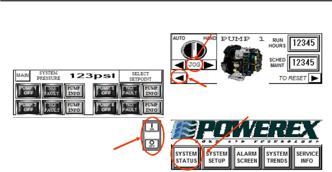
The Powerex scroll enclosure air compressor has a power control switch and a touch screen or HMI panel on the front to allow operation and monitoring of the unit. See Controls section for details on operating the unit using the touch screen.
The switch below the screen controls power to the
motor starters. When the system is energized the HMI screen will be lit and active, but the motors will not run until the ON button is pushed. When ON is pushed, the center section of the switch will illuminate, enabling PLC control of the system, and will remain lit until the OFF button is pushed. The OFF button on the switch may be used to stop the compressors at any time. The switch does not turn off power to the panel so be sure to lock out the power source before opening the panel for service.
NOTE: The "Jog" function on the HMI screen overrides the ON switch. The motors will operate if the Jog button is continually depressed. To reach "JOG" press the SYSTEM STATUS button, then press PUMP INFO for the pump module you want to jog.
The PUMP INFO screen is shown below. Press the “JOG” button to jog pumps.
Use the < arrow button to go back and select the next pump.
If the SYSTEM STATUS screen is not visible, go back to the MAIN screen and select SYSTEM STATUS. (see below)
Pg 7

10HP - 20HP Scroll Enclosure Air Compressors
OPERATION
BEFORE START UP
1.Make sure all safety warnings, labels and instructions have been read and understood before continuing.
2.Remove any shipping materials, brackets, etc.
3.Confirm that the electric power source and ground have been firmly connected.
4.Check the belts for tightness.
5.Be sure all pressure connections are tight.
6.Check to be certain all safety relief valves etc., are the proper size.
7.Securely mount all panels and guards.
8.Check that all fuses, circuit breakers etc., are the proper size.
9.Make sure the inlet filter is properly installed.
10.Secure the area in front of the compressor to prevent unauthorized access during this check. Remove the front access panel so that the motor pulley on each set is visible.
Check motor rotation before operating the unit.
Turn power on the unit and exercising extreme caution, use the HMI display/input screen to jog each motor. (To reach the JOG function, select SYSTEM STATUS from the MAIN screen, then select PUMP INFORMATION for each installed pump/motor set) Correct rotation is CW looking at the pulley from the motor side. All motors should rotate in the same direction. If all or any of the motors rotate incorrectly, lock out the power, correct the input wiring and recheck. Restore the front access panel before operating the unit.
INITIAL START UP AND SET UP OF THE CONTROL
The control is programmed at the factory and default settings are installed. To access certain control functions you will need to enter a seven digit authorization code. You may select your own code. We recommend using the last seven digits of the unit serial number.
To enter the code, from the SYSTEM STATUS screen touch SELECT SETPOINT.
Go to PG 2 of the SELECT SETPOINT screen.
The second page of the SETUP screen will appear.
Pg 8
Touch the rectangle to enter the Authorization Code and enter seven digits using the keypad that appears. Powerex suggests using the last seven digits of the serial number.
START-UP AND OPERATION
1.Follow all the procedures under “Before start-up” before attempting operation of the compressor.
2.Switch on the electric source.
3.Verify the display screen is lit.
4.If an isolation valve is installed between the compressor unit and the air receiver, make sure it is open. Close the isolation valve between the air receiver and the facility piping.
5.Pushing the ON button below the touch screen will allow unit to start and operate automatically. Pushing the OFF button will stop the motors, but the HMI screen will remain active.
6.If the pressure does not rise, turn the unit off, the unit is running backwards. Have a qualified electrician switch the breaker OFF and exchange two out of the three phases of electrical source. If pressure is rising, allow the compressor unit to run. Each compressor motor will automatically turn off as the pressure rises and the maximum operating pressure is reached. Pressure settings may be adjusted as described below.
7.Open the isolation valve between the air receiver and the facility piping. The compressor will start and stop each pump as needed to maintain the pressure between the high and low set points.
8.After a few hours and again after a few days, check the display screen to see if the ALARM screen has appeared. If a HIGH TEMPERATURE or MOTOR OVERLOAD condition occurs, the alarm screen will appear and the affected pump-motor will be taken out of service. If the chosen settings are causing the motors to start too frequently, the ALARM screen will appear and the MOTOR WARNING indicator will illuminate. Motor warning will not take the motor out of service, but the user should take action to prevent motor overload and damage. To reduce motor starting frequency, adjust the set points to a wider range between High and Low and possibly increase the differential. If starting is still too frequent, a larger or additional air receiver will be needed.
10HP - 20HP Scroll Enclosure Air Compressors
OPERATION Cont’d
SHUT-DOWN
1.Stop the compressor by pushing the OFF button. NOTE: If the compressor rotates in reverse for more than
five seconds, the check valve needs to be cleaned or replaced.
2.Switch the breaker OFF if the compressor is not to be used for a long period of time.
STOPPING THE COMPRESSOR DURING EMERGENCY OPERATION
Stop the compressor by pushing the OFF button or by turning the power off at the main disconnect panel.
MULTI-STAGE CONTROL
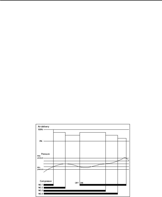
As this compressor uses plural air ends, it employs multi-stage control. It can start and stop each air end according to pressure and air consumption, automatically select the number of air ends in accordance with air consumption and achieve optimum and uniform operation at all times as well as energy-saving and labor-saving operation. 1. Multi-stage control - Among air ends which are operating under group control, it stops the air end which has been operating for a longer time and restarts the air end whose operating time has been shorter, thus resulting in equalization of operating time of each air end and operation with a min.
quantity of air ends in accordance with air consumption and energy-saving operation by eliminating waste of electricity. The chart below shows the relationship between pressure and the quantity of air ends operating for an SEQ model. The same concept is applied to 3 air ends for an SET and 2 for an SED. 2. Automatic Alteration: When air demand allows one or more air ends to remain idle, the control will automatically shift operation to equalize usage after 10 minutes. If air demand increases and pressure drops, the control will energize additional air ends as needed, starting the one with the longest off time first. The control will also de-energize air ends as pressure rises.
3.The control allows the user to adjust the pressure settings. To minimize power consumption, the user should select the lowest maximum pressure that is suitable for the operations being performed. The smallest gap between minimum and maximum pressure that avoids too frequent motor starting should also be selected.
4.The control will automatically prevent multiple motors from starting simultaneously by inserting a three second delay.
The sequence is an example of operation of SEQ2007.
SET1507 operate 3 air ends, SED1007 operate 2 air ends.
Pg 9
10HP - 20HP Scroll Enclosure Air Compressors
OPERATION Cont’d
OPERATING PANEL & SETTINGS
The Scroll Enclosure Air Compressor is controlled by a PLC programmed at the Powerex factory. The operating status is displayed on the HMI– touch screen panel on the front of the compressor unit. The touch screen allows the user to select operating parameters within predetermined limits set at the factory. The touch screen also allows the user to change the display to get more information about the operation of the individual compressor modules and to take action based on alarms and warnings. This enclosed scroll system utilizes a PLC for alternation and will change the pump sequence (Lead, Lag1, Lag2 etc) after every start or after 10-minutes, which ever happens first. The HMI offers a MIN and MAX system setpoint and three calculated pressure differential settings. (Standard, Min and Max)
The factory default settings for HIGH and LOW Operating Pressures are:
Standard Models |
90-116 PSIG |
|
|
High Pressure Models |
119-145 PSIG |
|
|
Differential setting default is STANDARD
Limits to difference between HIGH and LOW setpoints:
Maximum Differential |
50 PSIG |
|
|
Minimum Differential |
16 PSIG |
|
|
The control automatically divides the range between HIGH and LOW Operating Pressure into equal operating intervals. The differential for the operating intervals may be adjusted by selecting STANDARD, MIN or MAX on the set up screen.
In STANDARD, the differential will be automatically set to have a slight overlap between the individual pump intervals. Each interval will be 135% of the possible minimum value.
In MIN, the differential will be automatically set to divide the available range into equal intervals with no overlap. The selection will result in the most frequent starting of the electric motors for a given Operating Pressure range.
NOTE: more frequent motor starting can lead to reduced motor life. Exceeding 17.5 starts per hour will cause a warning display.
In MAX, the differential will be automatically set to increase the overlap as compared to the Standard setting. Each interval will be 235% of the possible minimum interval. Select this mode to minimize the frequency of motor starts. Motor start frequency can be reduced by using larger air receiver tanks, selecting a wider range between HIGH and LOW Operating
Pressure and by selecting the widest differential.
To minimize power consumption, select the lowest possible HIGH operating pressure and the smallest differential that avoids exceeding the motor start frequency limit.
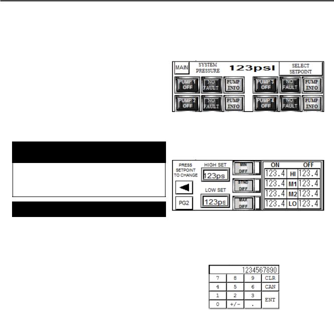
PERFORMING PRESSURE ADJUSTMENTS
The above display is the SYSTEM STATUS screen. (For SED and SET models, only two and three sets of buttons/ indicators will be shown).
To adjust pressure settings, touch the SELECT SETPOINT button. The screen will change to this display:
Touch the screen at either the HIGH SET or LOW SET button/indicator. A key pad display will be shown. Enter the desired pressure setting using the key pad and touch ENT.
CLR is clear, use it to backspace one digit.
CAN or Cancel, voids the whole input, use it to start over.
Pressure settings must be entered as whole numbers, no decimal or factions. The individual intervals will be calculated and shown in the display boxes on the right side of the setting screen. If number are entered that are out of the allowed range, the input will be scaled back to the range limit.
Pg 10
 Loading...