

Powerex SED1007, SET1507HP, SEQ2007, SED1007HP, SEQ2007HP User Manual
...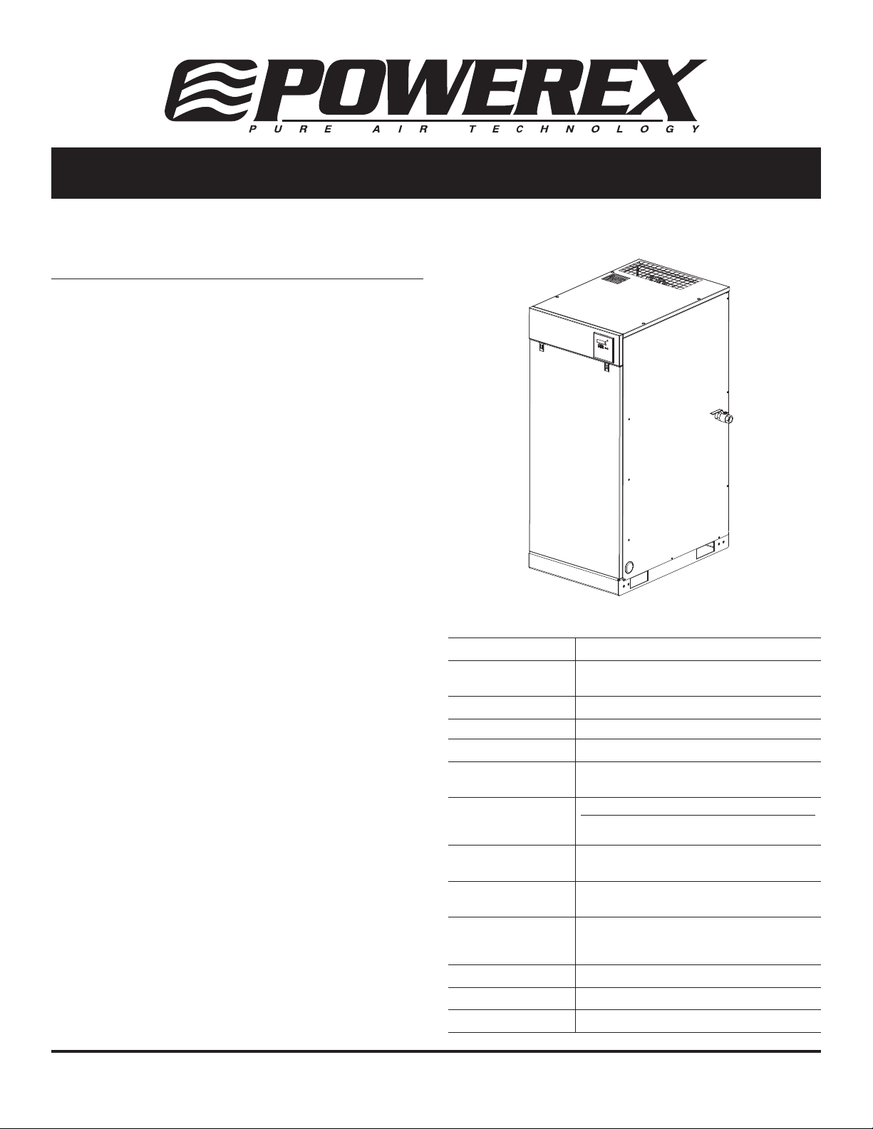
Scroll Enclosure Air Compressor
Please read and save these instructions. Read carefully before attempting to assemble, install, operate or maintain the product
described. Protect yourself and others by observing all safety information. Failure to comply with instructions could result in
personal injury and/or property damage! Retain instructions for future reference.
Description
Powerex Scroll Enclosure Air Compressors are designed to
supply continuous oil-free air by using the most advanced
scroll technology. These turn-key packages are extremely
quiet and offer electronic control that will reduce electrical
power consumption.
The Powerex Oilless Rotary Scroll Air Compressor has
advanced scroll compressor technology through the
development of a completely oilless unit. The Powerex Scroll
Compressor offers a dynamically balanced air end which
insures vibration-free operation. The rotary design permits a
continuous 100% duty cycle. No oil separation, oil fi ltration,
or inlet valves are required on the Powerex Scroll unit. The
compressor is virtually maintenance free.
The Powerex Oilless Rotary Scroll Air Compressor is based on
the theory of scroll compression. A scroll is a free standing,
intricate spiral bounded on one side by a solid, fl at plane or
base. A scroll set, the basic compression element of a scroll
compressor, is made up of two identical spirals which form
right and left hand parts. One of these scroll components
is indexed or phased 180° with respect to the other so the
scrolls can mesh. Crescent-shaped gas pockets are formed
and bounded by the spirals and the base plate of both
scrolls. As the moving scroll is orbited around the fi xed scroll,
the pockets formed by the meshed scrolls follow the spiral
toward the center and diminish in size. The moving scroll is
prevented from rotating during this process so the 180° phase
relationship of the scrolls is maintained. The compressor’s
inlet is at the outer boundary of the scrolls. The entering
gas is trapped in two completely opposite gas pockets and
compressed as the pockets move toward the center. The
compressed gas is discharged through the outlet at the center
of the fi xed scroll so no valves are needed.
Specifi cations
Product SED, SET, SEQ, SEH and SEO Series
Performance
Specifi cations
Lubrication Grease-fi lled Bearings / Dry Scroll
Operating Voltages 3Ø 208-230/460 Volts, 60 Hz
Compression Cycle Scroll
Motor Overload
Protection
Pressure Settings
Working Pressure
Overpressure
Protection
Outlet Air
Connections
Minimum
Recommended Tank
Sizes
Unit Isolation Standard All Units
Drive 3V Belt
Control Panel UL508A Listed for medical units
See Page 2
IEC Motor Overload Relay
Cut-In: 94 psig Cut-Out: 116 psig
Cut-In: 116 psig Cut-Out: 145 psig
(High Pressure Unit)
Safety Valve Factory Set and Sealed
See Page 2
See Page 5, Chart 2
Powerex • 150 Production Drive • Harrison, OH 45030 • USA
1-888-769-7979
IN558804AV 6/12
Scroll Enclosure Air Compressors
Safety Guidelines
This manual contains information that is very important
to know and understand. This information is provided for
SAFETY and to PREVENT EQUIPMENT PROBLEMS. To help
recognize this information, observe the following symbols.
Danger indicates an imminently
hazardous situation which, if
not avoided, will result in death or serious injury.
Warning indicates a potentially
hazardous situation which, if
not avoided, could result in death or serious injury.
Caution indicates a potentially
hazardous situation which, if
not avoided, MAY result in minor or moderate injury.
Notice indicates important
information, that if not
followed, may cause damage to equipment.
Unpacking
After unpacking the unit, inspect carefully for any damage
that may have occurred during transit. Make sure to tighten
fi ttings, bolts, etc., before putting unit into service.
Do not operate unit if damaged
during shipping, handling
or use. Damage may result in bursting and cause injury or
property damage.
The compressor nameplate should be checked to see if the
unit is the correct model and voltage as ordered.
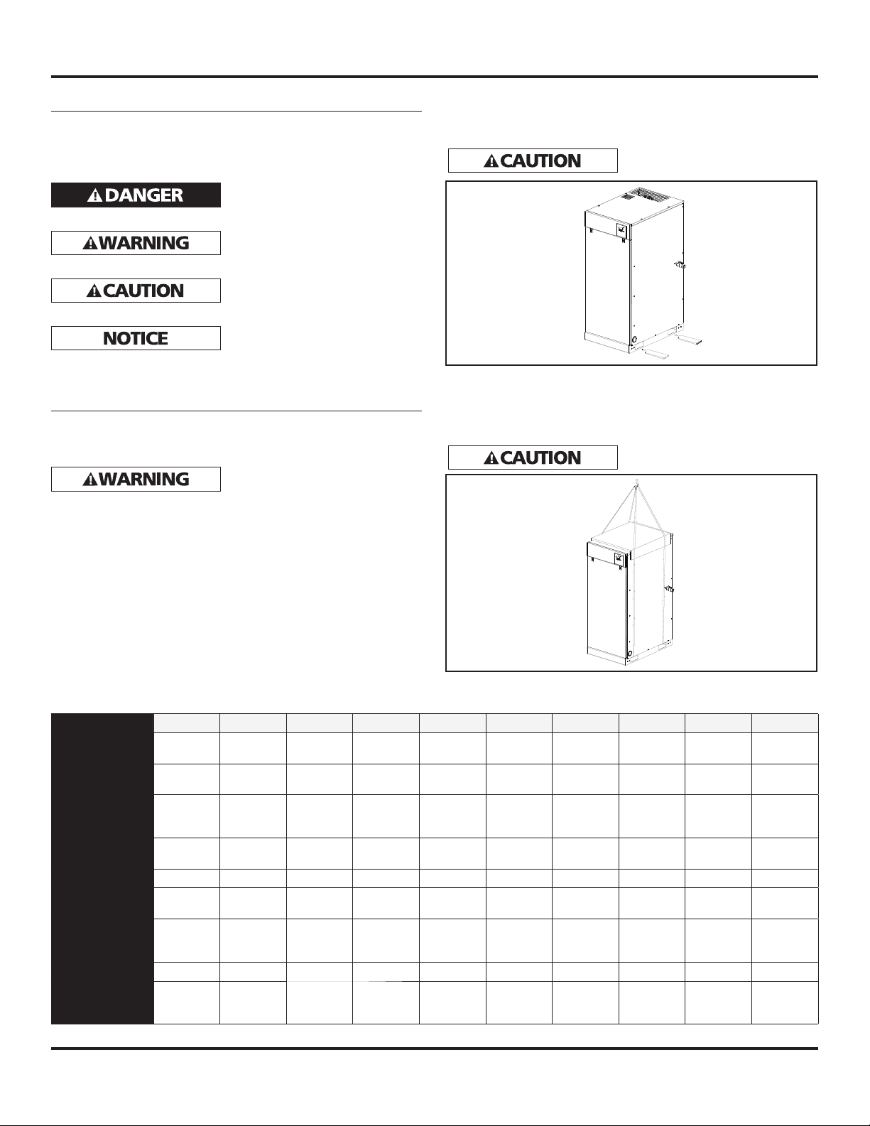
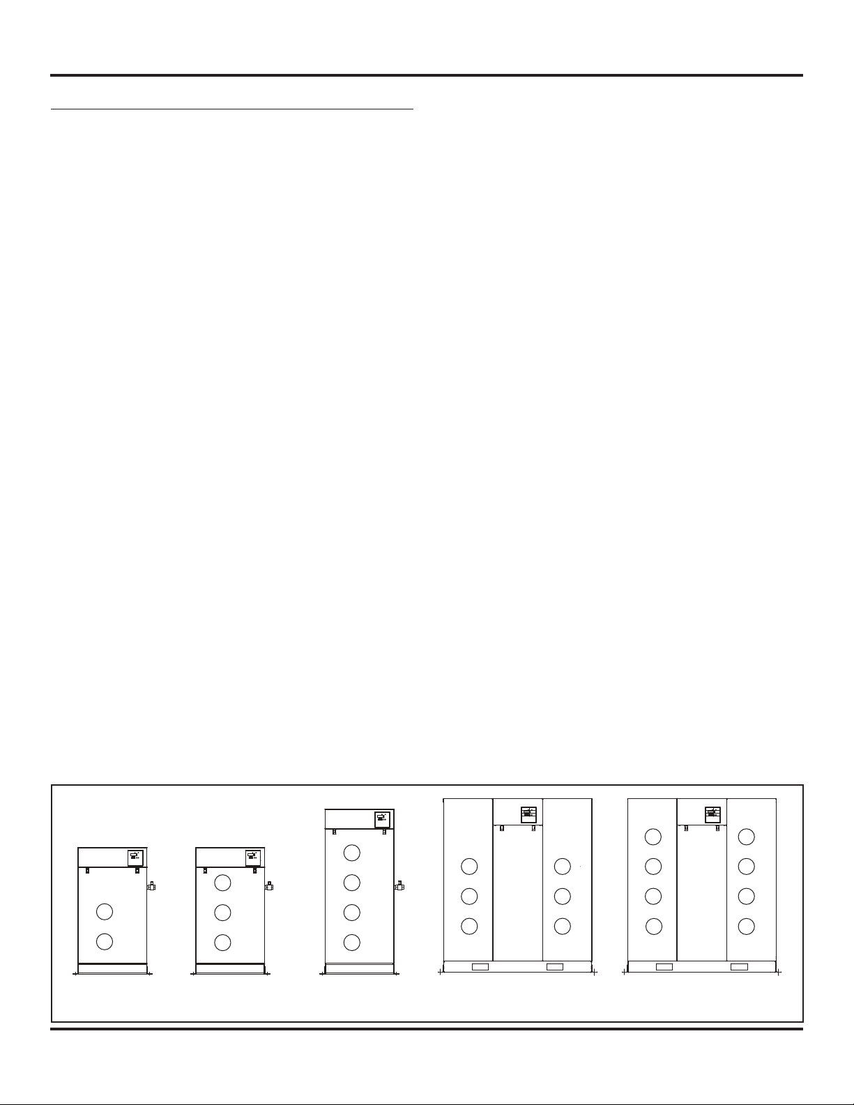
PRECAUTIONS DURING TRANSPORTATION AND MOVEMENT
TRANSPORTATION BY FORKLIFT
Use openings for forklift under both sides of the unit.
Avoid damaging the panel with
tips of the forklift.
Figure 1
TRANSPORTATION BY CRANE
Use openings at the bottom of the unit to lift up by cable,
lifting straps and etc. Make sure all lifting devices are rated
for the maximum load.
Be sure to use pads in order to
protect panels.
Figure 2
Performance Specifi cations
Model SED1007 SED1007HP SET1507 SET1507HP SEQ2007 SEQ2007HP SEH3007 SEH3007HP SEO4007 SEO4007HP
Installed Motor
HP
Maximum
Pressure PSIG
Performance
SCFM @
100 PSIG
FLA*
208 / 230 / 460
Noise Level dB(A) 53 53 56 56 58 58 59 59 60 60
Discharge
Connection
Dimensions
in Inches
(L x W x H)
Weight (lbs) 620 620 800 800 1030 1030 1945 1945 2320 2320
Discharge Air
Temp. °F
* Full System Amps
10 10 15 15 20 20 30 30 40 40
116 145 116 145 116 145 116 145 116 145
30.4 25.6 45.6 38.4 60.8 51.2 91.2 76.8 121.6 102.4
30.6 / 27.6 /
13.8
3/4 inch 3/4 inch 3/4 inch 3/4 inch 1 inch 1 inch 1-1/2 inch 1-1/2 inch 1-1/2 inch 1-1/2 inch
38 x 26 x 47 38 x 26 x 47 38 x 26 x 47 38 x 26 x 47 38 x 26 x 61 38 x 26 x 61 58 x 45 x 65 58 x 45 x 65 58 x 45 x 65 58 x 45 x 65
< Intake
temp.
+49°F
30.6 / 27.6 /
13.8
< Intake
temp.
+49°F
45.9 / 41.4 /
20.7
< Intake
temp.
+52°F
45.9 / 41.4 /
20.7
< Intake
temp.
+52°F
61.2 / 55.2 /
27.6
< Intake
temp.
+63°F
61.2 / 55.2 /
27.6
< Intake
temp.
+63°F
91.8 / 82.8 /
41.4
< Intake
temp.
+63°F
91.8 / 82.8 /
41.4
< Intake
temp.
+63°F
122.4 /
100.4 / 55.2
< Intake
temp.
+63°F
100.4 / 55.2
< Intake
2
122.4 /
temp.
+63°F
4. Never use rubber hoses, plastic piping or soldered joints
in any part of the compressed air or gas system. The
compressor and system piping must be compatible.
Breathable Air Warning
This compressor / pump is not equipped and should
not be used “as is” to supply breathing quality air. For
any application of air for human consumption, you
must fi t the air compressor / pump with suitable in-line
safety and alarm equipment. This additional equipment
is necessary to properly fi lter and purify the air to
meet minimal specifi cations for Grade D breathing as
described in Compressed Gas Association Commodity
Specifi cation G 7.1 - 1966, OSHA 29 CFR 1910. 134,
and / or Canadian Standards Associations (CSA).
DISCLAIMER OF WARRANTIES
IN THE EVENT THE COMPRESSOR IS USED FOR THE
PURPOSE OF BREATHING AIR APPLICATION AND PROPER
IN-LINE SAFETY AND ALARM EQUIPMENT IS NOT
SIMULTANEOUSLY USED, EXISTING WARRANTIES ARE
VOIDED, AND POWEREX DISCLAIMS ANY LIABILITY
WHATSOEVER FOR ANY LOSS, PERSONAL INJURY OR
DAMAGE.
5. The compressor will shutoff when the pressure reaches a
predetermined maximum pressure. Care should be used
since the compressor may suddenly restart automatically
when the pressure drops to the predetermined minimum
pressure. Never assume the compressor is ready for
service just because the unit is stopped.
Release all pressure
before attempting to install, service, relocate or
perform any maintenance.
6. Keep clear of all moving parts especially if the compressor
is operating with the door panel removed for inspection
or repair.
Do not touch HOT
compressor such as the air end, discharge pipe,
aftercooler, motor, etc.
7. Keep fl ammable gases away from the compressor. Parts
of the compressor become very hot during operation and
the vapors from fl ammable gases may cause the unit to
explode.
General Safety Information
The operator of this compressor must take the necessary
precautions to prevent the level of danger indicated by these
symbols. The operator is also required to read and understand
this instruction manual and all safety warnings, labels, etc.
Any employer allowing the use of this compressor in their
fi eld of work must distribute this instruction manual to
all users. The employer must also ensure all users read,
understand and follow the instructions as described in the
manual, safety warnings, labels, etc.
1. Read and understand all safety warnings and
instructions before operating this compressor.
Failure to read and follow all safety warnings
may result in serious personal injury or death.
Property damage and/or compressor damage
may also occur if all warnings are not followed.
2. Air used for breathing or food processing must
meet O.S.H.A. 29 C.F.R. 1910.134 or C.F.R. 178.3570
regulations.
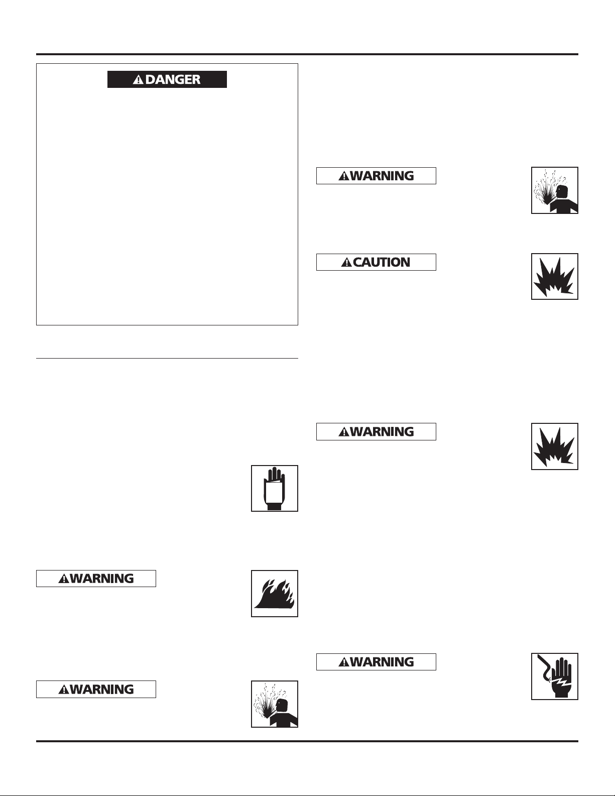
Motors, electrical
equipment and
controls can cause electrical arcs that will ignite a
fl ammable gas or vapor. Never operate or repair in
or near a fl ammable gas or vapor. Never store
fl ammable liquids or gases in the vicinity of the compressor.
3. Safety Valves or Relief Valves used on this compressor
must be in accordance with ANSI/ASME B19 safety
standards. Improperly sized Safety Valves will result in
serious personal injury or death.
Do not remove the
panel or try to
service the air compressor while the compressor is
running or while the air receiver is under pressure.
Serious personal injury or death will occur.
MANUAL
8. Never use fl ammable or toxic solvents to clean the
compressor or any of the unit’s parts.
9. Do not remove or tamper with any safety devices,
guards, panels or insulation parts while compressor is in
operation. All guards or panels must be in place before
starting or operating the compressor.
Install a properly
Valve in the discharge piping ahead of or before
a shut-off valve, heat exchanger, orifi ce, etc. The
compressor or part of the system could rupture or
explode if a Safety Relief Valve is not installed.
10. Do not change the pressure setting of the Safety Relief
Valve. Do not replace the Safety Relief Valve with a plug
or restrict the Safety Relief Valve. The system or the
compressor may be over-pressurized if the Safety Relief
Valve is tampered with in any way.
11. Do not service the compressor or any compressor part
while the unit is in operation.
12. Do not remove, disconnect or tamper with the High
Temperature Shutdown Switch. The High Temperature
Shutdown Switch must be installed on the compressor
to protect against high temperatures damaging the
compressor.
13. All electrical connections should be made by a qualifi ed
electrician.
Disconnect all
the compressor before opening the electrical box
or before servicing the unit. High voltage may be
present.
14. Never remove or alter any safety warning labels, tags,
etc. located on or provided with compressor.
Scroll Enclosure Air Compressors
from the system
parts of the
sized Safety Relief
power supplies to
3
Scroll Enclosure Air Compressors
General Safety Information
(Continued)
15. Always provide a clean air source for your compressor.
Keep all piping direct and short when using an outside
air source.
16. Locate compressor inlet system away from possible
ingestion of fl ammable or toxic vapors, water, dirty air or
air temperatures exceeding 104°F.
17. Never set the pressure to a higher setting than the one
provided from the factory.
18. Check all gauges daily to be sure the compressor is
operating correctly.
19 Follow all directions for maintenance. Check all safety
devices according to instructions.
20. Never attempt to lift or move the compressor except
when using the proper lifting procedures.
21. Make sure all electrical components follow the National
Electric code and all state and local codes when installing
the compressor.
22 Do not operate the compressor if unusual noise or
vibration occurs.
23. Keep all panels in place at all times.
24. Standard motors are not appropriate for dirty, wet or
explosive areas.
25. All service should be performed by trained and qualifi ed
people only.
26. The Drive Belt tension should be checked often during
initial operation of the compressor.
27. Never substitute oil bath or oil wetted fi lters for the inlet
fi lters provided with the compressor.
Installation
INSTALLATION SITE
1. The scroll compressor must be located in a clean, well lit
and well ventilated area. A contaminated area can clog
the intake fi lter and / or intake metal mesh.
2. The area should be free of excessive dust, toxic or
fl ammable gases, moisture and direct sunlight.
3. Never install the compressor where the ambient
temperature is higher than 104°F or lower than 32°F
or where humidity is high. High humidity will cause
electrical short circuit and rusting of components.
4. Clearance must allow for safe, effective inspection and
maintenance. 24 inch of clearance for sides, 40 inch
clearance from the top is recommended.
5. If necessary, use metal shims or leveling pads to level the
compressor. Never use wood to shim the compressor.
VENTILATION
1. If the scroll compressor is located in a totally enclosed
room, an exhaust fan with access to outside air must be
installed.
2. Never restrict the cooling fan exhaust air.
3. Vent the exhaust air outside to prevent the compressor
from operating at high temperatures and shutting down.
4. Never locate the compressor where hot exhaust air from
other heat generating units may be pulled into the unit.
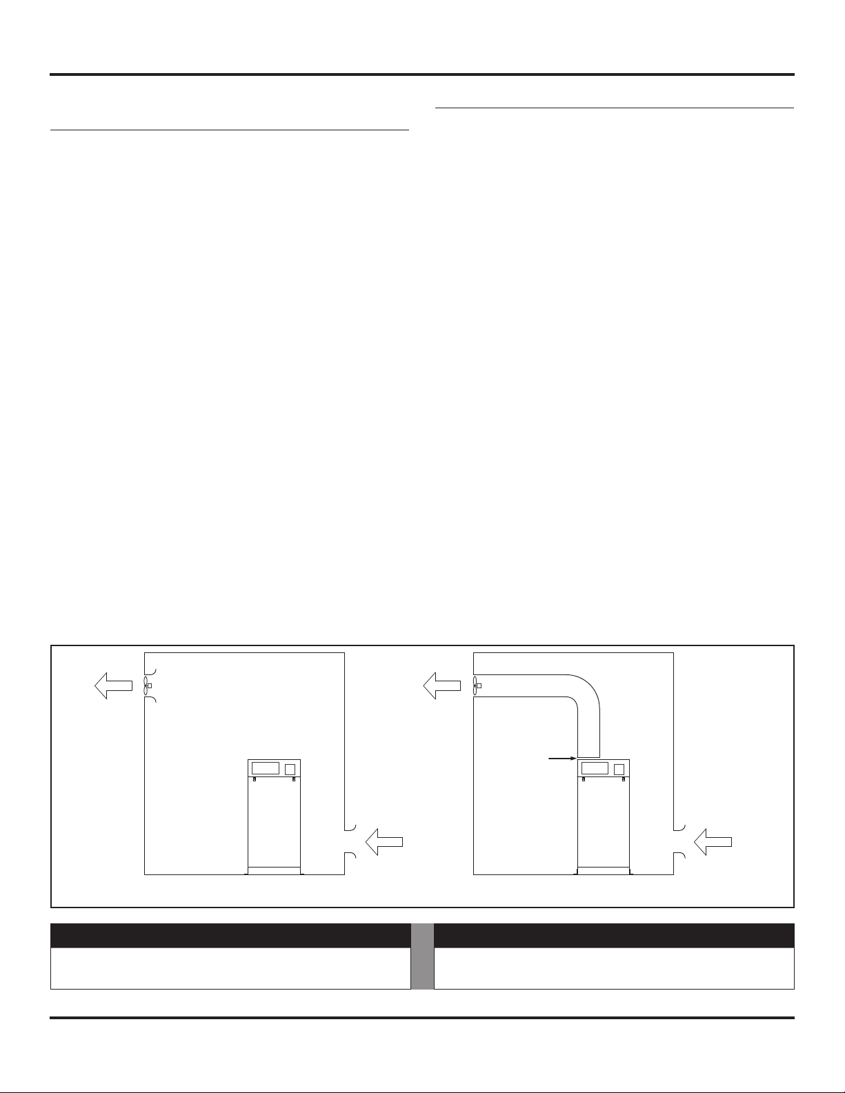
SUGGESTED VENTILATION SYSTEM
1) The following ventilation capacity is designed to keep
the temperature rise inside the room to be max. 10°F.
Since the calculation is based on zero static pressure,
the actual ventilation capacity should be larger than the
capacity value listed in Chart 1.
EXHAUST
AIR OUT
FRESH
Figure 3
Model - Setup A 10 HP 15 HP 20 HP 30 HP 40 HP
Ventilation
Capacity (cfm)
Chart 1
2650 3885 5300 7770 10595
Setup A Setup B
AIR IN
EXHAUST
AIR OUT
Model - Setup B 10 HP 15 HP 20 HP 30 HP 40 HP
Ventilation
Capacity (cfm)
4
8 inches to
12 inches
Clearance
FRESH
AIR IN
885 1415 1770 2830 3535

Scroll Enclosure Air Compressors
Installation (Continued)
2) Install the exhaust duct in order to minimize the
pressure lost of the ducting. Keep the distance between
the inlet duct and the compressor exhaust to be at least
12 inches for ease of maintenance. Intake section of the
duct should be larger than the dimension of compressor
exhaust shown below:
WIRING
All electrical hook-ups must be performed by a qualifi ed
electrician. Installations must be in accordance with local and
national electrical codes.
1. Use solderless terminals to connect the electric power
source.
2. Remove front panel.
3. Remove the rectangle electrical box cover located
beneath air inlet fi lter on the right front of the unit.
4. Connect the power inlet cable to the inlet power
junction block located on the inlet side of all starter
connections.
Consult your NEC and local codes for wire size
PIPING
These units do not include air receivers. An air receiver can
be purchased separately. Please consult our distributors. Use
Chart 2 as a guideline for sizing the air receiver.
SAFETY VALVES
The fl ow capacity of a safety valve should be equal to or
greater than the capacity of the compressor.
1. The pressure setting of the safety valve must not be
greater than the maximum working pressure of the air
receiver.
2. Safety valves should be placed ahead of any possible
blockage point in the system, i.e. shutoff valve.
3. Avoid connecting the safety valve with any tubing or
piping.
4. Manually operate the safety valve every six months to
avoid sticking or freezing.
Model 10 HP 15 HP 20 HP 30 HP 40 HP
Air Receiver Minimum
Capacity (gallons)
Chart 2
1. Make sure the piping is lined up without being strained
or twisted when assembling the piping for the scroll
compressor.
2. Appropriate expansion loops or bends should be installed
at the compressor to avoid stresses caused by changes in
hot and cold conditions.
3. Piping supports should be anchored separately from the
compressor to reduce noise and vibration.
4. Never use any piping smaller than the compressor
connection.
5. Use fl exible hose to connect the outlet of the compressor
to the piping so that the vibration of the compressor
does not transfer to the piping.
30 60 60 110 160
5
Scroll Enclosure Air Compressors
Operation
BEFORE START UP
1. Make sure all safety warnings, labels and instructions
have been read and understood before continuing.
2. Remove any shipping materials, brackets, etc.
3. Confi rm that the electric power source and ground have
been fi rmly connected.
4. Check the belts for tightness.
5. Be sure all pressure connections are tight.
6. Check to be certain all safety relief valves, etc., are
correctly installed.
7. Securely mount all panels and guards.
8. Check that all fuses, circuit breakers, etc., are the proper
size.
9. Make sure the inlet fi lter is properly installed.
10. Confi rm that the drain valve is closed.
11. Visually check the rotation of the compressor pumps.
The rotation should be counterclockwise if viewing the
compressor from the pulley or belt side of the motor or
the air end. If the rotation is incorrect, have a qualifi ed
electrician correct the incomming T1 and T2 connections.
START-UP AND OPERATION
1. Follow all the procedures under “Before start-up” before
attempting operation of the compressor.
2. Switch on the electric source breaker.
3. Make sure electric source lamp lights up and that the
caution code or alarm code does not show up on the
display.
Note: The alarm lamp light will come on if a temperature
sensor is not connected. If the sensor is not connected, have a
qualifi ed service person reconnect the sensor.
4. Open the discharge valve completely.
5. Push ON button and check that the compressor operates
without excessive vibration, unusual noises or leaks.
6. Close the discharge valve completely.
7. If the pressure does not rise on a three phase unit,
turn the unit off, the unit is running backwards.
Have a qualifi ed electrician switch the breaker OFF
and exchange two out of three phases of electric
source.
8. Check the discharge pressure. Also make sure the air
pressure rises to the designated pressure setting by
checking the discharge pressure gauge.
CONTROL LOGIC SEQUENCING ORDER
Since the compressors are designed using multiple air-ends,
they are using multiplex controller. The controller will start
and stop each air-end according to the pressure and air
consumption.
1) Alternating Control:
The controller will equalize the operating hours on
each air-end. It will alternate between the air end with
the most running time and the air end with the lowest
running time.
2) Prevention of long term operation:
When an air-end has been operating longer than the settime, the controller will alternate to the air-end with the
lowest running time. This will prevent one air end from
running continuously for too long and will equalize the
running time between the available air ends.
SHUT-DOWN
1. Stop the compressor by pushing the OFF button.
NOTE: If the compressor rotates in reverse for more than fi ve
seconds, the check valve needs to be cleaned or replaced.
2. Switch the breaker OFF if the compressor is not to be
used for a long period of time.
STOPPING THE COMPRESSOR DURING NORMAL
OPERATION
1. Close the discharge valve.
2. Allow the air pressure to build and the compressor to
stop.
3. Turn the compressor off by pushing the OFF button.
STOPPING THE COMPRESSOR DURING EMERGENCY
OPERATION
Stop the compressor by pushing the OFF button or by turning
the power off at the main disconnect panel.
3
2
1
SED SET
Figure 4 - Control Logic Sequencing Order
2
1
4
3
2
1
SEQ
4
3
2
1
SEH
(6)3
(5)2
1
(4)
3
2
1
SEO
(8)
4
3 (7)
2 (6)
1 (5)
6
Scroll Enclosure Air Compressors
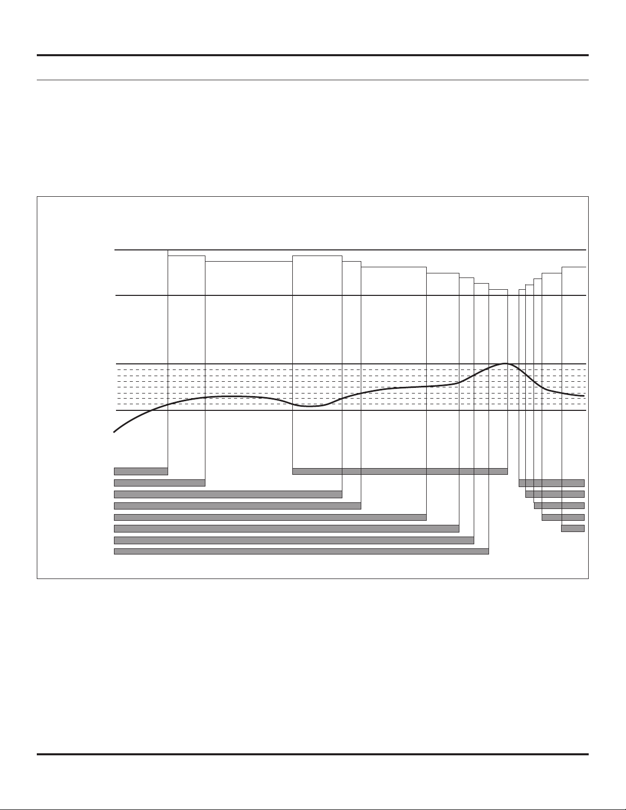
Multi-Stage Control
As this compressor uses plural air ends, it employs multi-stage control. It can start and stop each air end according to pressure
and air consumption, automatically select the number of air ends in accordance with air consumption and achieve optimum and
uniform operation at all times as well as energy-saving and labor-saving operation.
1. Multi-stage control
Among air ends which are operating under group control, it stops the air end which has been operating for a longer
time and restarts the air end whose operating time has been shorter, thus resulting in equalization of operating time
of each air end and operation with a min. quantity of air ends in accordance with air consumption and energy-saving
operation by eliminating waste of electricity.
Multi-stage control
Ratio of
100%
air consumption
Ration of Load
0%
Max
pressure
Pressure
Min
pressure
No 1
No 2
No 3
Compressor
No 4
No 5
No 6
No 7
No 8
OFF ON
2. Prevention of long-term operation
When operating time of an air end exceeds the initial setting time, it changes operation from that air end to the one
which has stopped, prevents long-term operation of one air end, lengthens the lifetime of air ends and equalizes the
operating time of air ends.
7
Scroll Enclosure Air Compressors
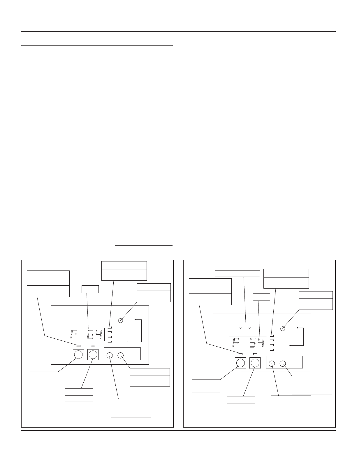
Operating Panel
DISPLAY MODE
There are fi ve modes of display: Operation, Caution, Service,
Set, and Time.
1. Operation Mode (Default Mode) - To toggle between
display, push item button. You can obtain operating
information (pressure, hours, operating conditions)
which are useful for daily maintenance and inspection.
It functions whether compressor operates or stops. (See
Charts 3 and 4).
2. Caution Mode - In order to select Caution Mode, push
Mode button so that Caution Mode light is illuminated.
By Item button, you can determine causes and conditions
when problems occur as indicated in Charts 5 and 6. It
functions only when compressor stops (2.5 second delay
before each pump starts).
3. Service Mode - In order to select Service Mode, push
Mode Selector Switch so that Service Mode light is
illuminated. By Item Selector Switch, you can determine
causes and conditions when problems occur, as indicated
in Charts 5 and 7. It functions only when compressor
stops.
4. Set Mode - Push Mode button so that Set Mode light
is illuminated. Item button can show each of the set
contents as shown in Chart 8. It functions only when
compressor stops.
5. Time Mode (Only STO and SEH) - In order to select the
Time Mode, push Mode Button so that Time Mode light
is illuminated. By utilizing Item Button, you can scroll the
display shown in the chart below. Compressor must be
turned off before selecting the Time Mode.
The Early Caution maintenance alarm becomes effective
by installing a Early Caution maintenance connector. By
doing so, the maintenance alarm will be activated at
7800 hours (2000 hours earlier than maintenance
alarm 1).
CHANGING MINIMUM AND MAXIMUM PRESSURE
SETTING
1. Change to Set Mode by utilizing Mode button.
2. Display maximum pressure or minimum pressure by
utilizing Item button.
3. You can decrease set pressure by pushing OFF button and
Item button at the same time.
4. You can increase set pressure by pushing Off button and
Mode button at the same time.
5. Cut off circuit breaker and switch on breaker again.
Restrictions:
• Maximum pressure does not exceed fi gure initially set at
our plant.
• Pressure difference between maximum and minimum
pressure is 14.5 psig or over.
• Minimum pressure is 29 psig.
• The display will round all pressure increments to the
nearest psi.
RESETTING OF MAINTENANCE COUNTERS
1. Change to “Set Mode” by utilizing Mode button.
2. Display “Maintenance Time 1” by utilizing Item Switch.
3. Press Reset Switch.
4. Cut off circuit breaker and switch on breaker again.
Mode Display Light
Compressor
Operating Lamp
Indicates selected
display mode
Compressor
Run
ON
Display
OFF
Indicates selected
display mode
Reset
Operation Mode
Caution Mode
Service Mode
Set Mode
Mode Item
ON Switch
Starts the unit
OFF Switch
Stops the unit
MODE button
Selects the mode
to be displayed
Figure 5 - Operating Panel (SED, SET, and SEQ)
Reset Switch
Performs various
resettings
ITEM button
Selects the information to be displayed
Unit Display
Indicates selected unit
Compressor
Operating Lamp
Indicates selected
display mode
Compressor
Run
UNIT 1 UNIT 2
ON
Mode Display Light
Indicates selected
display mode
Display
Mode Item
OFF
Operation Mode
Time Mode
Set Mode
ON Switch
Starts the unit
OFF Switch
Stops the unit
MODE button
Selects the mode
to be displayed
Figure 6 - Operating Panel (SEO and SEH)
Reset Switch
Performs various
resettings
Reset
ITEM button
Selects the information to be displayed
8
●
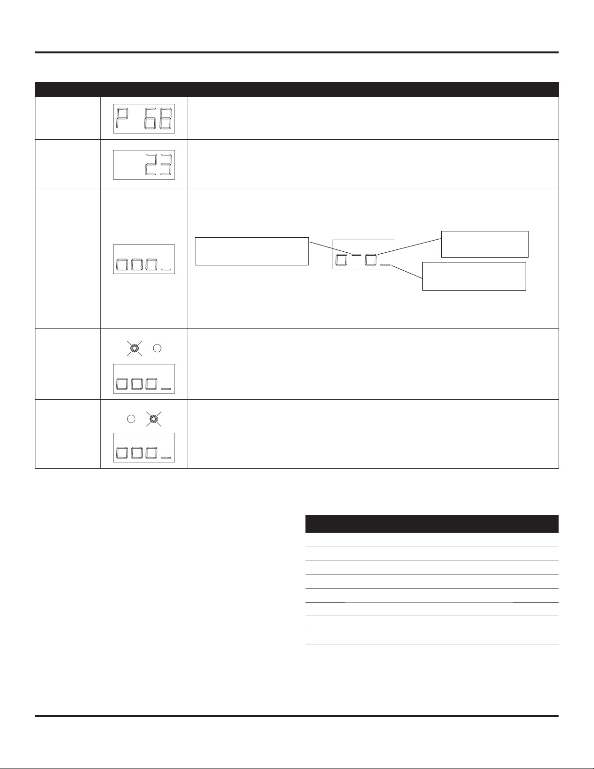
Operating Panel (Continued)
Items Display Explanation
Scroll Enclosure Air Compressors
Pressure
Operating
Time
Operating
conditions
Operating
condition of
Unit No. 1
(SEO and
SEH series)
Displays compressor outlet pressure in psig
(Display on the left means 68 psig.)
Displays operating time in hours x10.
(Display on the left means 230 hours.)
* Number of Hours that any pump is running x load factor
(between 0 to 1 depending on how many pumps are running)
Displays operating condition of of air ends No. 1-4
Displays operating condition of air ends No. 1,2,3 and 4 from left to right of the display
(The air end that are located on the bottom of the Unit is designated as No 1)
means specifi c air
Indicates emergency stop
when “hyphen” lights up.
In the above example, No. 1 and No. 3 air ends are in operation, No.2 air end is in an
emergency stop and No. 4 air end is off.
If the unit has no air end to display, the indicator will always display “underline”.
Displays operating condition of present Unit No. 1 (left side) which consists of air ends
no. 1~4.
Display contents are the same as illustrated above.
end in operation
Compressor is off when
“underline” lights up
Operating
condition of
Unit No. 2
(SEO and
SEH series)
Chart 3 - Operation Mode
Displays operating condition of present Unit No. 2 (right side) which consists of air ends
no. 1~4.
Display contents are the same as illustrated above.
Operation Mode Operating Situation
dX10 Initial stage of stop
dX11 Normal stop
dX12 Dryer preliminary start-up
dX20 Initial stage of start
dX21 Start 1
dX22 Start 2
dX30 Initial stage of load
dX31 Normal load
Chart 4 - Detail of Operating Mode X: Air end No.
9
 Loading...