

Page 1
Scroll Enclosure Air Compressor 30 HP to 40 HP
Please read and save these instructions. Read carefully before attempting to assemble, install, operate or maintain the product described.
Protect yourself and others by observing all safety information. Failure to comply with instructions could result in personal injury and/or
property damage! Retain instructions for future reference.
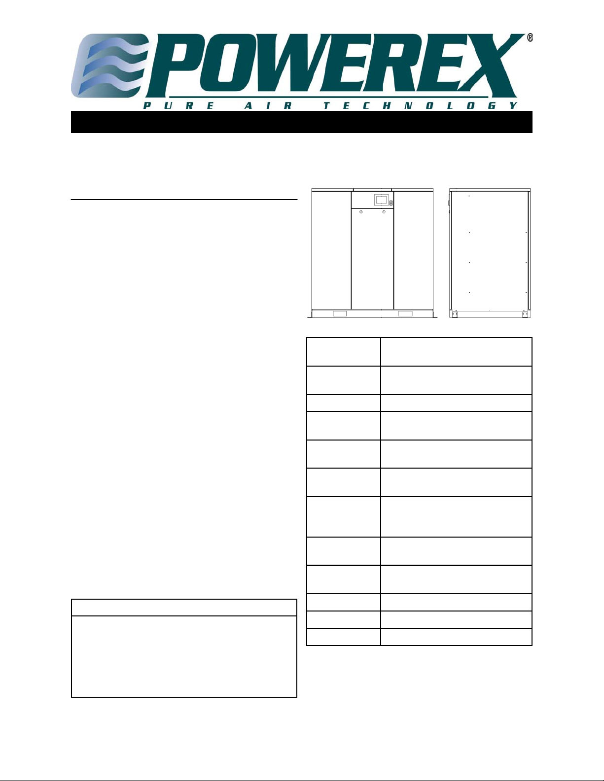
DESCRIPTION
GENERAL
Powerex Scroll Enclosure Air Compressors are designed to
supply continuous oil-free air by using the most advanced
scroll technology. These turn-key packages are extremely quiet
and offer electronic control that will reduce electrical power
consumption.
The Powerex Oil-less Rotary Scroll Air Compressor has
advanced scroll compressor technology through the
development of a completely oil-less unit. The Powerex Scroll
Compressor offers a dynamically balanced air end which
insures vibration-free operation. The rotary design permits a
continuous 100% duty cycle. No oil separation, oil filtration,
or inlet valves are required on the Powerex Scroll unit. The
compressor is virtually maintenance free.
The Powerex Oil-less Rotary Scroll Air Compressor is based
on the theory of scroll compression. A scroll is a free standing,
intricate spiral bounded on one side by a solid, flat plane or
base. A scroll set, the basic compression element of a scroll
compressor, is made up of two identical spirals which form
right and left hand parts. One of these scroll components is
indexed or phased 180° with respect to the other so the scrolls
can mesh. Crescent-shaped gas pockets are formed and
bounded by the spirals and the base plate of both scrolls. As
the moving scroll is orbited around the fixed scroll, the pockets
formed by the meshed scrolls follow the spiral toward the
center and diminish in size. The moving scroll is prevented
from rotating during this process so the 180° phase
relationship of the scrolls is maintained. The compressor’s
inlet is at the outer boundary of the scrolls. The entering gas is
trapped in two completely opposite gas pockets and
compressed as the pockets move toward the center. The
compressed gas is discharged through the outlet at the center
of the fixed scroll so no valves are needed.
Table of Contents
Specifications Pg 1–2 Troubleshooting Pg 14
Safety Guidelines Pg 2-3 Electrical Pg 15-17
Installation Pg 3-7 Parts List Pg 18-19
Operation Pg 7-11 Warranty Pg 23-24
Maintenance Pg 12-13
SPECIFICATIONS
Product SE Series Enclosed Scroll Air
Compressor
Performance
Specifications
Lubrication Grease-filled Bearing
Operating
Voltages
Compression
Cycle
Motor Overload
Protection
Pressure Settings Cut in: 90 psig Cut out: 116 psig
Overpressure
Protection
Outlet Air
Connections
Tank Sizes See Page 6, Chart 3
Drive 3V Belt
Control Panel UL508A Listed
See page 2
3Ø - 208-230/460/575 Volts, 60 Hz;
380 volts, 50 Hz
Scroll
Motor Protector/Circuit Breaker
Cut in: 119 psig Cut out: 145 psig
(High Pressure Units)
Safety Valve Factory Set and Sealed
See page 2
Powerex - 150 Production Drive - Harrison, Ohio 45030 - USA
1-888-769-7979 - www.powerexinc.com
IN590403AV
Pg 1
01/14
Page 2
30 HP– 40 HP Scroll Enclosure Air Compressors
SPECIFICATION CHART
Model HP Max
Pressure
PSIG
SEH3007 30 116 91.2 208/230/380/460/575 59 1 Inch 67°F
SEH3007HP* 30 145 75 208/230/380/460/575 59 1 Inch 80°F
SEO4007 40 116 121.6 208/230/380/460/575 60 1 Inch 67°F
SEO4007HP* 40 145 100 208/230/380/460/575 60 1 Inch 80°F
*HP indicates high pressure model.
SCFM @
Max
Pressure
Voltage Noise
Level
dB(A)
Discharge
Connection
Discharge
Air
Approach
Temp
SAFETY GUIDELINES
This manual contains information that is very important to
know and understand. This information is provided for
SAFETY and to PREVENT EQUIPMENT PROBLEMS. To
help recognize this information, observe the following
symbols. MAKE SURE EVERYONE OPERATING OR
SERVICING THE COMPRESSOR READS AND
UNDERSTANDS ALL THE INFORMATION PROVIDED.
Danger indicates and
imminently hazardous situation which, if not avoided,
WILL result in death or injury.
Warning indicates a potentially
hazardous situation which, if not avoided, COULD result in
death or serious injury.
Caution indicates a potentially
minor or moderate injury.
Notice indicates important
information, that if not
followed, may cause damage to equipment.
GENERAL SAFETY INFORMATION
Since the air compressor makes up a high pressure system,
the following safety precautions must be observed at all
times.
1. Read all manuals included with this product
carefully. Be thoroughly familiar with the
controls and the proper use of the
equipment.
2. Follow all local electrical and safety codes
as well as in the United States, the National
Electrical Codes (NEC) and Occupational Safety and
Health Act (OSHA).
3. Only persons well acquainted with these rules of safe
operation should be allowed to use the compressor.
4. Keep visitors away and NEVER allow children in the
work area.
Pg 2
5. Wear safety glasses and use hearing
protection when operating the unit.
6. Do not stand on or use the unit as a
handhold.
7. Before each use, inspect compressed
air system and electrical components for signs of
damage, deterioration, weakness or leakage. Repair or
replace defective items before using.
8. Check all fasteners at frequent intervals for proper
tightness.
Motors,
electrical
equipment and controls can cause electrical arcs that will ignite a flammable gas or
vapor. Never operate or repair in or near a
flammable gas or vapor. Never store flammable liquids or
gases in the vicinity of the unit.
Never operate compressor pump without a
protective guard. This unit can start
automatically without warning. Personal
injury or property damage could occur
from contact with moving parts.
BREATHABLE AIR
WARNING
This unit is NOT equipped and should NOT be used “as
is” to supply breathing quality air. For any application of
air for human consumption, you must fit the air compressor with suitable in-line safety and alarm equipment.
This additional equipment is necessary to properly filter
and purify the air to meet minimal specifications for
Grade D breathing as described in Compressed Gas Association Commodity Specification for Air, OSHA, ANSI
and/or Canadian Standards Associations (CSA).
DISCLAIMER OF WARRANTIES
IN THE EVENT THE COMPRESSOR IS USED FOR THE
PURPOSE OF BREATHING AIR APPLICATION AND
PROPER IN-LINE SAFETY AND ALARM EQUIPMENT
IS NOT SIMUTANEOUSLY USED, EXISTING
WARRANTIES ARE VOID, AND POWEREX
DISCLAIMS ANY LIABILITY WHATSOEVER FOR ANY
LOSS, PERSONAL INJURY OR DAMAGE.
Page 3
30 HP - 40 HP Scroll Enclosure Air Compressors
GENERAL SAFETY CONT.
9. Do not wear loose clothing or jewelry that will get
caught in the moving parts of the unit.
Surface may be hot even if unit is stopped.
10. Keep fingers away from a running unit;
fast moving and hot parts will cause injury and/or burns.
11. If the equipment should start to vibrate abnormally,
STOP the unit and check immediately for the cause.
Vibration is generally a warning of trouble.
12. To reduce fire hazard, keep unit exterior free of oil,
solvent, or excessive grease.
An ASME code safety relief valve with a setting no higher
than the tank maximum allowable working pressure MUST
be installed in the air lines or in the tank of any compressor.
The ASME safety valve must have sufficient flow and
pressure ratings to protect the pressurized components from
bursting.
13. Never attempt to adjust ASME safety valve on
compressed air units. Keep safety valve free from paint
and other accumulations.
Never attempt to repair or modify a tank!
Welding, drilling or any other modification
will weaken the tank resulting in damage
from rupture or explosion. Always replace worn, cracked
or damaged tanks.
Drain liquid from tank daily.
14. Tanks rust from moisture build-up, which weakens the
tank. Make sure to drain tank regularly and inspect periodically for unsafe conditions such as rust formation and
corrosion.
15. Fast moving air will stir up dust and debris which may
be harmful. Release air slowly when draining moisture
or depressurizing a compressor system.
Do not lift or move unit without
appropriately rated equipment.
Be sure the unit is securely attached to lifting device used.
Do not lift unit by holding on to tubes or coolers. Do not
use unit to lift other attached equipment.
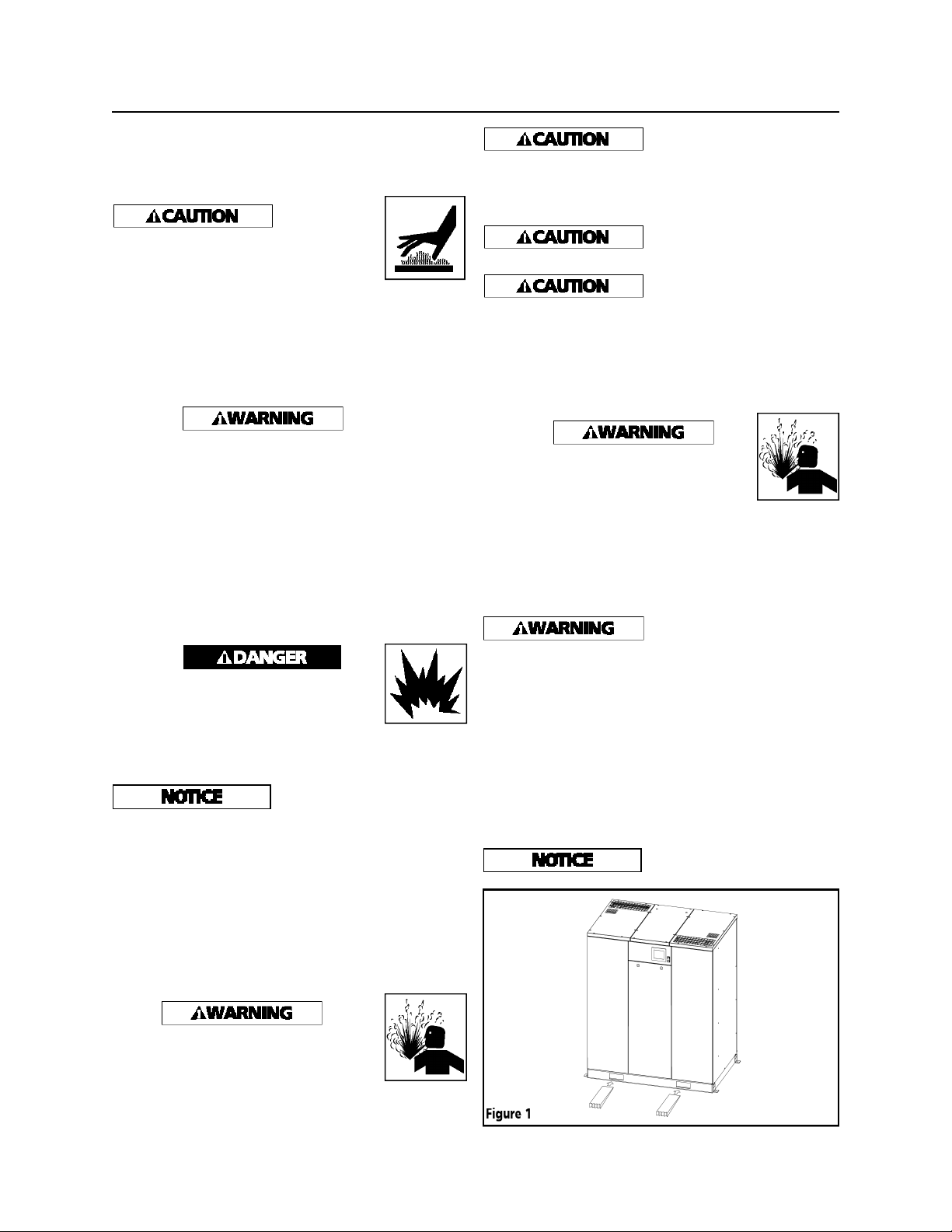
Never use the wood shipping
skids for mounting the unit.
Do not locate the air inlet near
steam, paint spray, sandblast
areas or any other source of contamination.
NOTE: If compressor system is installed in a hot, moist
environment, supply compressor pump with clean, dry
outside air. Pipe supply air in from external sources.
Failure to properly install a tank can lead to
cracks at the welded joints and possible
bursting or leakage.
UNPACKING
After unpacking the unit, inspect carefully for any damage
that may have occurred during transit. Make sure to tighten
fittings, bolts, etc., before putting unit into service.
Do not operate unit if damaged
during shipping, handling or
use. Damage may result in bursting and cause injury or
property damage.
The compressor nameplate should be checked to see if the
unit is the correct model and voltage as ordered.
PRECAUTIONS DURING TRANSPORTATION AND
MOVEMENT
TRANSPORTATION BY FORKLIFT
Use openings for forklift under both sides of the unit.
Avoid damaging the panel with
tips of forklift.
INSTALLATION
Disconnect, tag and lock out power source
then release all pressure from the system
before attempting to install, service, relocate
or perform any maintenance.
Pg 3
Page 4
30 HP - 40 HP Scroll Enclosure Air Compressors
INSTALLATION CONT.
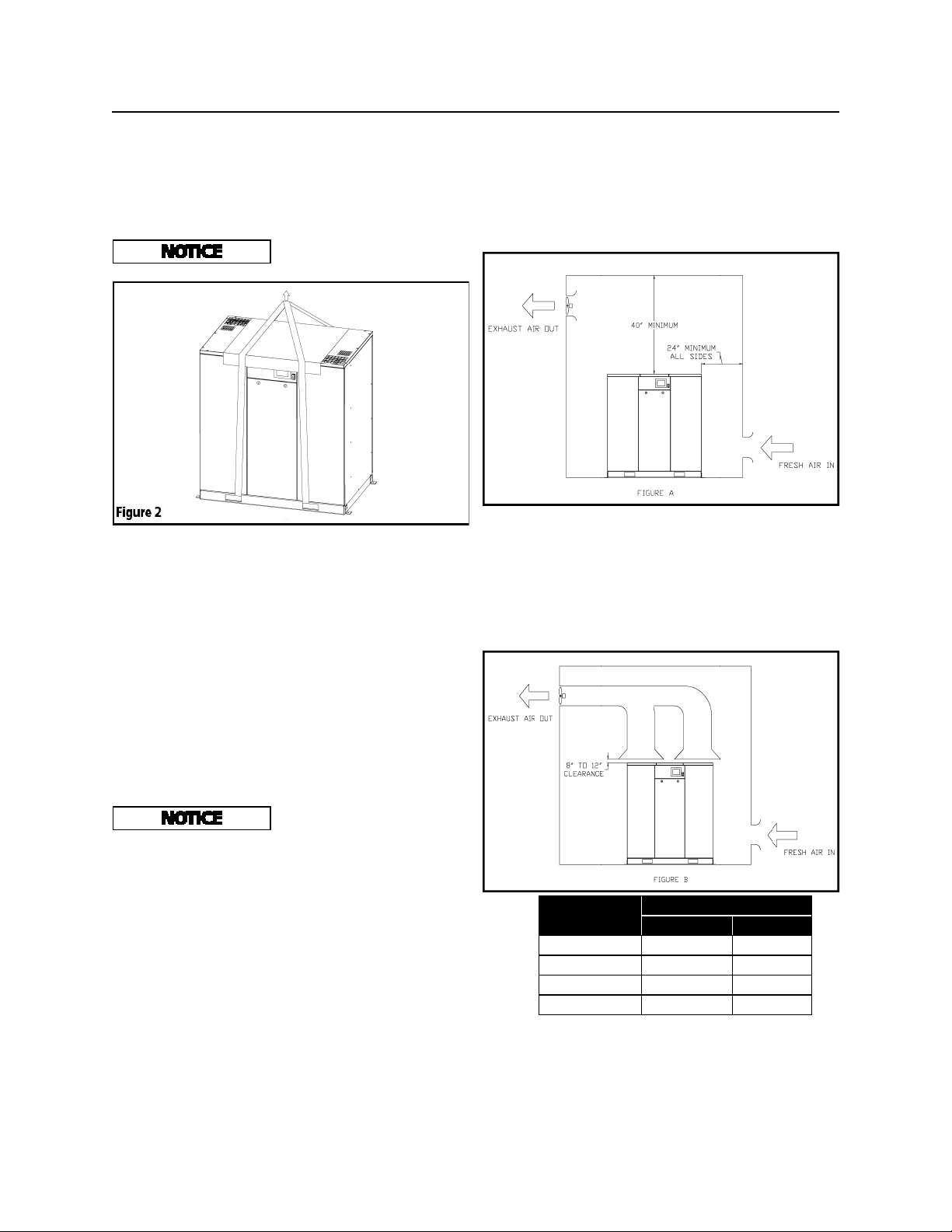
TRANSPORTATION BY CRANE
Use openings at bottom of the unit to lift up by cable, lifting
straps etc. Make sure all lifting devices are rated for the
maximum load.
INSTALLATION SITE
1. The scroll compressor must be located in a clean, well lit
and well ventilated area. A contaminated area can clog the
intake filter and / or intake metal mesh.
INSTALLATION SITE Cont.
2. The area should be free of excessive dust, toxic or
flammable gases, moisture and direct sunlight.
3. Never install the compressor where the ambient
temperature is higher than 104°F or where humidity is high.
High humidity will cause electrical short circuit and rusting
of components.
4. Clearance must allow for safe, effective inspection and
maintenance.
clearance from the top is required.
5. If necessary, use metal shims or leveling pads to level the
compressor. Never use wood to shim the compressor.
VENTILATION
1. If the scroll compressor is located in a totally enclosed
room, an exhaust fan with access to outside air must be
installed.
2. Never restrict the cooling fan exhaust air or the intake
cooling air.
3. Vent the exhaust air outside to prevent the compressor
from operating at high temperatures and shutting down.
4. Never locate the compressor where hot exhaust air from
other heat generating units may be pulled into the unit.
Be sure to use pads in order to
protect the panels.
A minimum of 24 inches of
clearance for sides, 40 inch
SUGGESTED VENTILATION SYSTEM
The temperature rise in the room must be kept to a maximum
of 10 F. The BTU capacity of the vent system should be sized
for the full operating HP rating of the compressor. Suggested
fan capacity at 0 static pressure is shown below. If static
pressure is higher, the fan capacity should be increased.
An exhaust duct may be installed to capture the warm air
exiting the compressor enclosure. The opening of the exhaust
duct should be about 6 inches larger on each side than the
vent openings on the compressor top panel. The duct should
not obstruct removal of the top panel for service. Leave between 8 and 12 inches of clearance. The CFM capacity of the
exhaust fan should be increased to compensate for duct flow
losses.
Model
Exhaust CFM Required
Figure A Figure B
SEH3007 7770 2830
SEH3007HP 7770 2830
Chart 1
SEO4007 10595 3535
SEO4007HP 10595 3535
Pg 4
Page 5
30HP - 40HP Scroll Enclosure Air Compressors
INSTALLATION Cont’d
WIRING
All wiring and electrical connections must be performed by
a qualified electrician. Installations must be in accordance
with local and national codes.
Overheating, short circuiting
and fire damage will result from
inadequate wiring.
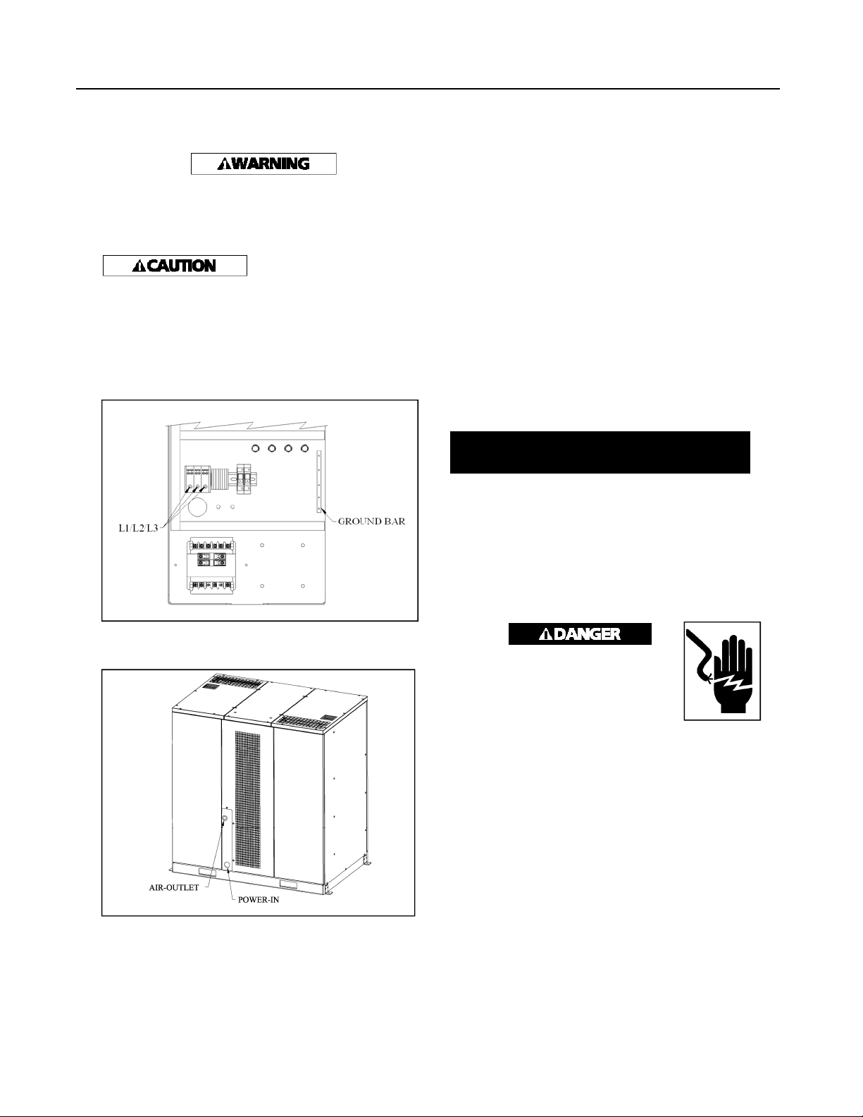
The Powerex Scroll Enclosure Air Compressor is completely factory wired and requires only a 3 phase supply
circuit. A set of terminals is provided for connection of the
supply conductors and ground conductor. See Figure 3
below for more detail.
Wiring must be installed in accordance with National Electric
Code and local codes and standards that have been set up
covering electrical apparatus and wiring. Consult the codes
and standards and observe local ordinances. Be certain that
adequate wire sizes are used, and that:
1. Service is of adequate ampere rating.
2. The supply line has the same electrical characteristics
3. Ensure the line wire is the proper size and that no other
gives the recommended wire sizes for horsepower of motor
provided.
Recommended wire sizes may be larger than the mini mum
set up by local ordinances. If so, use the large size wire to
prevent excessive line voltage drop.
Chart 2
(voltage cycles and phase) as the motor.
equipment is operated from the same line. The chart
MINIMUM WIRE SIZE
O
USE 75
HP
C COPPER WIRE
Three Phase
208V 230V 460V 575V
30 1 AWG 2 AWG 6 AWG 8 AWG
40 2/0 AWG 1/0 AWG 4 AWG 6 AWG
Figure 3
A 2 inch opening is provided for conduit or cord connection. See Figure 4 for opening location.
Figure 4
The additional wire cost is very small compared with the cost
of repairing or replacing a motor electrically “starved” by the
use of supply wires which are too small.
GROUNDING
Improperly grounded electrical components
are shock hazards. Make sure all the components are properly grounded to prevent death
or serious injury.
This product must be grounded. Grounding reduces the risk
of electrical shock by providing an escape wire for the
electrical current if short circuit occurs.
All electrical hook-ups must be performed by a qualified
electrician. Installations must be in accordance with local and
national electrical codes.
1. A service disconnect and fuses or a circuit breaker must be
installed to supply electric power to this compressor. Make
sure the circuit is sized to handle the full operating load as
shown in the table.
2. Remove the front panel to access the wiring area.
3. Using appropriate strain relief and cable management techniques, connect the power cable to the power junction block
and the ground wire to the ground bar.
Consult your NEC and local codes for wire size.
Pg 5
Page 6
30HP - 40HP Scroll Enclosure Air Compressors
INSTALLATION Cont’d
GENERAL FAULT DRY CONTACT CONNECTIONS
1. Turn the compressor off and lockout the power to the compressor per OSHA standards.
2. Remove the door panel from the scroll cabinet to access
the operating panel.
3. Output wires should be connected between terminals 10
and 11. The dry contacts are normally closed; when there is a
fault or loss of power to the system, the contacts open. The
contact rating is as follows: 240VAC/2A or 30VDC/2A,
maximum.
4. For larger load devices such as a horn or emergency light,
a relay should be used.
5. The signal wires should be between 24 and 12 AWG.
6. Replace the door panel to the scroll compressor cabinet.
7. Return the power to the compressor system.
PIPING
Never use plastic (PVC) pipe for compressed air. Serious
injury or death could result.
Any tube, pipe or hose connected to the unit must be able to
withstand the temperature generated and retain the pressure.
All pressurized components of the air system must have a
pressure rating higher than or equal to the ASME safety valve
setting. Incorrect selection and installation of any tube, pipe
or hose could result in bursting and injury.
Never install a shut-off valve between a compressor pump
and the tank without an appropriate safety valve. Personal
injury and/or equipment damage may occur. Never use
reducers in discharge piping.
The Powerex Scroll Enclosure Air Compressor has an ASME
safety relief valve at the outlet pipe nipple connection point.
When creating a permanently installed system to distribute
compressed air, find the total length of the system and select
pipe size from the chart. Bury underground lines below the
frost line and avoid pockets where condensation can gather
and freeze.
Apply air pressure to the piping installation and make sure all
joints are free from leaks BEFORE underground lines are
covered. Before putting the unit into service, find and repair
all leaks in the piping, fittings and connections.
Select the size of the air receiver so that the combined volume
of the air receiver and facility piping results in a long enough
cycle time to keep any individual motor from starting more
than once every 3.43 minutes. Selecting the widest possible
spread between high and low system set point pressure along
with the largest differential for each pump interval will
reduce the starting frequency.
The table below shows the recommended tank size in gallons
per model. Some conditions of air usage may require
additional volume.
Differential* SEH SEO
Min 240 240
Standard 200 200
Max 120 120
Chart 3
*
Pressure setting selected on control panel
1. Make sure the piping is lined up without being strained or
twisted when assembling the piping for the scroll compressor.
2. Appropriate expansion loops or bends should be installed
at the compressor to avoid stresses caused by changes in hot
and cold conditions.
3. Piping supports should be anchored separately from the
compressor to reduce noise and vibration.
4. Never use any piping smaller than the compressor
connection.
5. Use flexible hose to connect the outlet of the compressor to
the piping so that the vibration of the compressor does not
transfer to the piping.
REMOTE INTAKE PIPING
Powerex compressor systems with pipe thread connectors on
the intake filters are intended for installation with remote air
intake. Piping for the remote intake system should be
installed at the final operating site.
Under some conditions, the intake piping may facilitate the
condensation of humidity in the intake air stream into liquid
water.
THE INTAKE FILTERS SUPPLIED BY POWEREX WILL
NOT STOP INGESTION OF LIQUID WATER BY THE
PUMPS. LIQUID WATER GOING INTO THE PUMPS
WILL DAMAGE THE PUMPS AND VOID THE
WARRANTY.
liquid water in the intake piping before the air filters. Drip
legs must be sized with low enough air velocity to make sure
they are effective at capturing liquid water in the intake air
and must be maintained (drained) at frequent intervals to
make sure they remain effective.
Always install drip legs with
sufficient capacity to capture
Pg 6
Page 7
30HP - 40HP Scroll Enclosure Air Compressors
INSTALLATION Cont’d
SAFETY VALVES
Safety Valves must be installed on every receiver. The flow
capacity of a safety valve should be equal to or greater than
the capacity of the compressor.
1. The pressure setting of the safety valve must not be greater
than the maximum working pressure of the air receiver.
2. Safety valves should be placed ahead of any possible
blockage point in the system, i.e. shutoff valve.
3. Avoid connecting the safety valve with any tubing or
piping.
4. Manually operate the safety valve every six months to
avoid sticking or freezing.
CHECK VALVES
Do not install a check valve between the compressor and the
air receiver or facility piping. If a check valve is installed, the
compressor pressure sensor will see rapid pressure drops and
cause short cycling of the motors and other control problems.
ISOLATION VALVES
An isolation valve should be installed between the
compressor and the air receiver to facilitate maintenance.
Make sure the valve is open when operating the compressor.
A second isolation valve should be installed between the air
receiver and the facility piping.
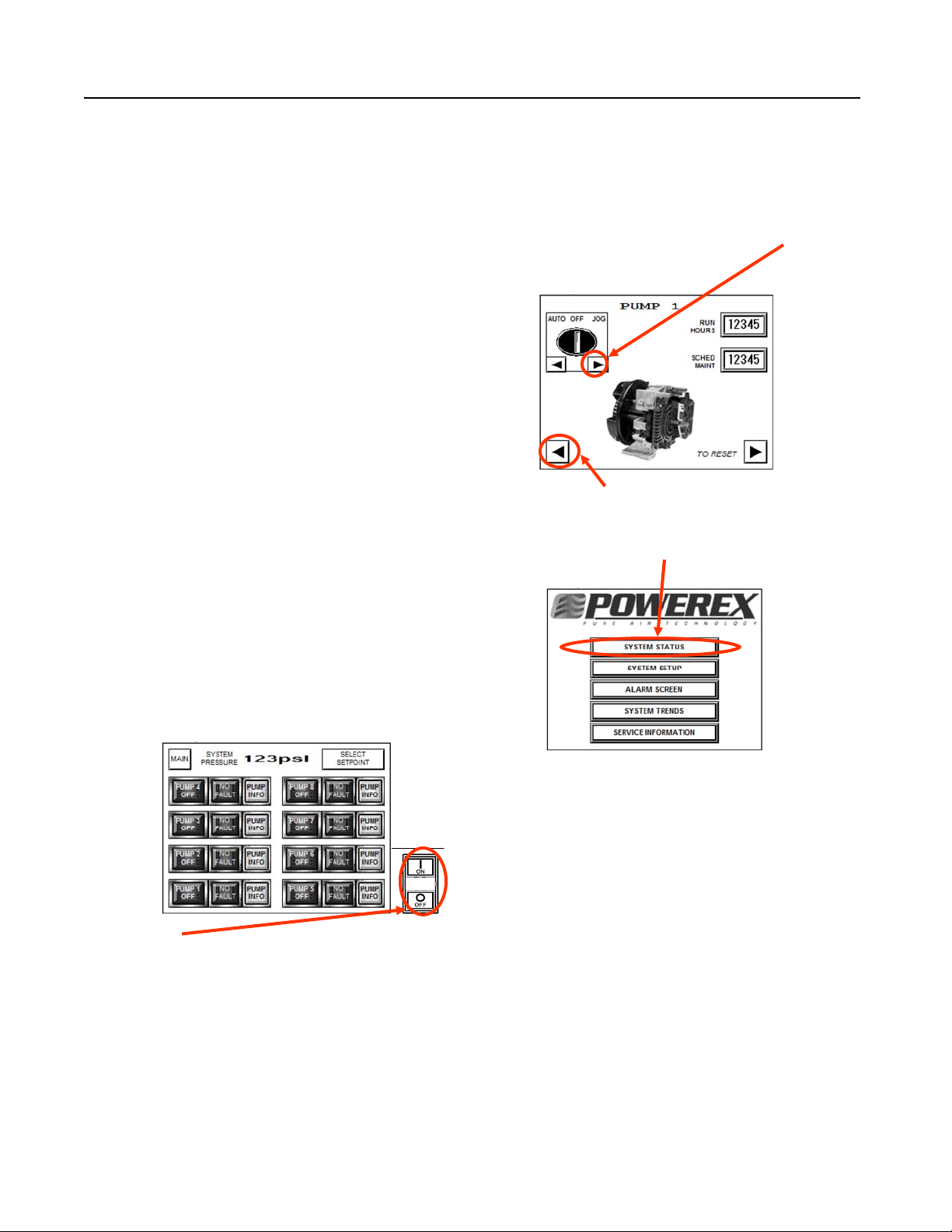
NOTE: The "Jog" function on the screen overrides the ON
switch. The motors will operate if the Jog button is
continually depressed. To reach "JOG" press the SYSTEM
STATUS button, then press PUMP INFO for the pump
module you want to jog.
The PUMP INFO screen is shown below. Press the > arrow
button to jog pumps.
Use the < arrow button to go back and select the next pump.
If the SYSTEM STATUS screen is not visible, go back to the
MAIN screen and select SYSTEM STATUS. (see below)
CONTROL PANEL - DISPLAY AND INPUT
The Powerex scroll enclosure air compressor has a power
control switch and a touch screen or HMI panel on the front
to allow operation and monitoring of the unit. See Controls
section for details on operating the unit using the touch
screen.
The switch beside the screen controls power to the motor
starters. When the system is energized the HMI screen will be
lit and the control screen is active, but the motors will not run
until the ON button is pushed. When ON is pushed, the center
section of the switch will illuminate, enabling the PLC control of the system, and will remain lit until the OFF button is
pushed. The OFF button on the switch may be used to stop
the compressors at any time. The switch does not turn off
power to the panel so be sure to lock out the power source
before opening the panel for service.
OPERATION
BEFORE START UP
1. Make sure all safety warnings, labels and instructions have
been read and understood before continuing.
2. Remove any shipping materials, brackets, etc.
3. Confirm that the electric power source and ground have
been firmly connected.
4. Check the belts for tightness.
5. Be sure all pressure connections are tight.
6. Check to be certain all safety relief valves etc., are the
proper size.
7. Securely mount all panels and guards.
8. Check that all fuses, circuit breakers etc., are the proper
size.
9. Make sure the inlet filter is properly installed.
10. Secure the area in front of the compressor to prevent
unauthorized access during this check. Remove the front-left
and right-rear access panels so that the motor pulley on each
set is visible.
Pg 7
Page 8
30HP - 40HP Scroll Enclosure Air Compressors
OPERATION Cont’d
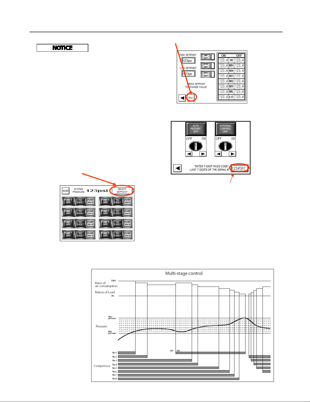
Go to PG 2 of the SELECT SETPOINT screen.
Check motor rotation before
operating the unit.
Turn power on the unit and exercising extreme caution, use
the HMI display/input screen to jog each motor. (To reach the
JOG function, select SYSTEM STATUS from the MAIN
screen, then select PUMP INFO for each installed pump/
motor set). Powerex wires the controls so all motors rotate in
the same direction. Correct rotation is CW looking at the
pulley from the motor side. If all or any of the motors rotate
incorrectly, lock out the power, correct the input wiring and
recheck. If any motor wiring is ever disturbed or modified,
recheck each motor for proper rotation direction. Restore the
access panels before operating the unit.
The second page of the SETUP screen will appear.
INITIAL START UP AND SET UP OF THE CONTROL
The control is programmed at the factory and default settings
are installed. To access certain control functions you will
need to enter a seven digit authorization code. You may select
your own code. We recommend using the last seven digits of
the unit serial number.
To enter the code, from the SYSTEM STATUS screen touch
SELECT SETPOINT.
Touch the rectangle to enter the Authorization Code and enter
seven digits using the keypad that appears. Powerex suggests
using the last seven digits of the serial number.
You may now return to the SYSTEM STATUS screen.
START-UP AND OPERATION
1. Follow all the procedures under “Before start-up” before
attempting operation of the compressor.
2. Switch on the electric source.
3.Verify the display screen is li t.
4. If an isolation valve is installed between the compressor
unit and the air receiver, make sure it is open. Close the
isolation valve between the air receiver and the facility
piping.
Pg 8
The sequence is an
example of operation
of SEO4007.
SEH3007 operate 6 air
ends.
Chart 4
Page 9

30HP - 40HP Scroll Enclosure Air Compressors
OPERATION Cont’d
5. Pushing the ON button beside the touch screen will allow
the unit to start and operate automatically. Pushing the OFF
button will stop the motors, but the HMI screen will remain
active.
6. If the pressure does not rise, turn the unit off, the unit is
running backwards. Have a qualified electrician switch the
breaker OFF and exchange two out of the three phases of
electrical source. If pressure is rising, allow the compressor
unit to run. Each compressor motor will automatically turn
off as the pressure rises and the maximum operating pressure
is reached. Pressure settings may be adjusted as described
below.
7. Open the isolation valve between the air receiver and the
facility piping. The compressor will start and stop each pump
as needed to maintain the pressure between the high and low
set points.
8. After a few hours and again after a few days, check the
display screen to see if the ALARM screen has appeared. If a
HIGH TEMPERATURE or MOTOR OVERLOAD condition
occurs, the alarm screen will appear and the affected
pump-motor will be taken out of service. If the chosen
settings are causing the motors to start too frequently, the
ALARM screen will appear and the MOTOR WARNING
indicator will illuminate. Motor warning will not take the
motor out of service, but the user should take action to
prevent motor overload and damage. To reduce motor starting
frequency, adjust the set points to a wider range between
High and Low and possibly increase the differential. If starting is still too frequent, a larger or additional air receiver will
be needed.
SHUT-DOWN
1. Stop the compressor by pushing the OFF button.
NOTE: If the compressor rotates in reverse for more than
five seconds, the check valve needs to be cleaned or replaced.
2. Switch the breaker OFF if the compressor is not to be used
for a long period of time.
STOPPING THE COMPRESSOR DURING
EMERGENCY OPERATION
Stop the compressor by pushing the OFF button or by turning
the power off at the main disconnect panel.
MULTI-STAGE CONTROL
As this compressor uses plural air ends, it employs
multi-stage control. It can start and stop each air end
according to pressure and air consumption, automatically
select the number of air ends in accordance with air
consumption and achieve optimum and uniform operation at
all times as well as energy-saving and labor-saving operation.
1. Multi-stage control - Among air ends which are operating
under group control, it stops the air end which has been
operating for a longer time and restarts the air end whose
operating time has been shorter, thus resulting in equalization
of operating time of each air end and operation with a min.
quantity of air ends in accordance with air consumption and
energy-saving operation by eliminating waste of electricity.
Chart 4 shows the relationship between pressure and the
quantity of air ends operating for an SEO model. The same
concept is applied to 6 air ends for an SEH.
2. Automatic Alteration: When air demand allows one or
more air ends to remain idle, the control will automatically
shift operation to equalize usage after 10 minutes. If air
demand increases and pressure drops, the control will
energize additional air ends as needed, starting the one with
the longest off time first. The control will also de-energize air
ends as pressure rises.
3. The control allows the user to adjust the pressure settings.
To minimize power consumption, the user should select the
lowest maximum pressure that is suitable for the operations
being performed. The smallest gap between minimum and
maximum pressure that avoids too frequent motor starting
should also be selected.
4. The control will automatically prevent multiple motors
from starting simultaneously by inserting a three second
delay.
OPERATING PANEL & SETTINGS
The Scroll Enclosure Air Compressor is controlled by a PLC
programmed at the Powerex factory. The operating status is
displayed on the HMI– touch screen panel on the front of the
compressor unit. The touch screen allows the user to select
operating parameters within predetermined limits set at the
factory. The touch screen also allows the user to change the
display to get more information about the operation of the
individual compressor modules and to take action based on
alarms and warnings. This enclosed scroll system utilizes a
PLC for alternation and will change the pump sequence
(Lead, Lag1, Lag2 etc) after every start or after 10-minutes,
which ever happens first. The HMI offers a MIN and MAX
system setpoint and three calculated pressure differential
settings. (Standard, Min and Max)
The factory default settings for HIGH and LOW Operating
Pressures are:
Standard Models 90-116 PSIG
High Pressure Models 119-145 PSIG
Differential setting default is STANDARD
Limits to difference between HIGH and LOW setpoints are:
Maximum Differential 50 PSIG
Minimum Differential 16 PSIG
Pg 9
Page 10

30HP - 40HP Scroll Enclosure Air Compressors
OPERATION Cont’d
The control automatically divides the range between HIGH
and LOW Operating Pressure into equal operating intervals.
The differential for the operating intervals may be adjusted by
selecting STANDARD, MIN or MAX on the set up screen.
In STANDARD, the differential will be automatically set to
have a slight overlap between the individual pump intervals.
Each interval will be 135% of the possible minimum value.
In MIN, the differential will be automatically set to divide the
available range into equal intervals with no overlap. The
selection will result in the most frequent starting of the
electric motors for a given Operating Pressure range.
NOTE: more frequent motor starting can lead to reduced
motor life. Exceeding 17.5 starts per hour will cause a
warning display.
In MAX, the differential will be automatically set to increase
the overlap as compared to the Standard setting. Each interval
will be 235% of the possible minimum interval. Select this
mode to minimize the frequency of motor starts. Motor start
frequency can be reduced by using larger air receiver tanks,
selecting a wider range between HIGH and LOW Operating
Pressure and by selecting the widest differential.
Touch the screen at either the HIGH SETPOINT or LOW
SETPOINT button/indicator. A key pad display will be shown.
Enter the desired pressure setting using the key pad and touch
ENT.
CLR is clear, use it to backspace one digit.
CAN or Cancel, voids the whole input, use it to start over.
Pressure settings must be entered as whole numbers, no
decimal or factions. The individual intervals will be
calculated and shown in the display boxes on the right side of
the setting screen. If number are entered that are out of the
allowed range, the input will be scaled back to the range
limit.
ALARM SIGNALS
To minimize power consumption, select the lowest possible
HIGH operating pressure and the smallest differential that
avoids exceeding the motor start frequency limit.
PERFORMING PRESSURE ADJUSTMENTS
The above display is the SYSTEM STATUS screen. (For the
SEH model, only six sets of buttons/indicators will be
shown).
To adjust pressure settings, touch the SELECT SETPOINT
button. The screen will change to this display:
The PLC control for the scroll enclosure compressor will
display the ALARM screen and activate the GENERAL
FAULT indicator on the alarm screen display if either of the
two conditions occurs:
1. High temperature at the sensor located at the after cooler
inlet. Each compressor module has its own sensor. A high
temperature condition will result in the power to that motor
being shut off. The GENERAL FAULT alarm display will
stay on and the circuit will stay off even after the sensor
cools, and can only be restored when the alarm is cleared by a
user. If a high temperature condition occurs, the reason
should be determined and corrected before restarting the
circuit as un-repairable damage to the scroll pump may result
from operation with repeated high temperature alarms.
2. Motor Overload, if the current to the motor exceeds the
setting of the adjustable motor protector, the contactor
associated with that motor is de-energized, and that motor
will not run. The alarm display and condition is maintained
until the alarm is cleared and the motor protector reset. The
circuit will be restarted as needed. If a motor overload occurs,
Pg 10
Page 11

OPERATION Cont’d
the root cause should be determined and corrected or motor
damage may result.
The user can activate the acknowledge function (button
labeled ACKN) to allow the display to go back to SYSTEM
STATUS or any other screen. Touch the VIEW button to
advance to a screen showing which pump-motor assembly is
in fault and for what reason. The fault will display and the
affected pump-motor will be disabled until the RESET button
is pushed.
The PUMP MAINT indicator will activate when the running
hours of any pump accumulates to a required maintenance
interval. The system is designed for multiple pumps to accumulate hours evenly and for maintenance intervals to be approached simultaneously. To prevent nuisance PUMP
MAINT indications, all applicable maintenance counters
should be reset after the required maintenance actions are
performed. Use ACKN to allow the STATUS screen or other
screens to be displayed. Touch the VIEW button to advance
to the next screen. Consult the maintenance chart 6 and scroll
air compressor manual for details of what maintenance ne e d s
to be performed. To reset the PUMP MAINT indicator for an
individual pump, open the PUMP INFO screen for that pump,
hit the RESET button and use the keypad display to enter the
authorization code when prompted.
Motor Warning: The control also tracks how many times per
hour an individual motor is called on to start. If the starts per
hour exceed 17.5, there is an increased risk of motor damage.
The warning is displayed, but the system is not shut down.
The user can select a wider operating pressure differential to
reduce the starts per hour or install a larger air receiver. The
ACKN button, which will have to be pressed for each motor
in alert, allows the display to be shifted back to SYSTEM
STATUS or any other screen before the warning automati-
30HP - 40HP Scroll Enclosure Air Compressors
cally resets itself at the end of the hour. The RESET button
will not clear the warning.
ALARM LOG
A record of all alarm or warning events is kept in the alarm
log. Reset status is tracked as well. The alarm log is
maintained as long as the unit is powered and for up to three
days after power is removed from the control.
SYSTEM TRENDS
The following additional information is available by selecting
the SYSTEM TRENDS from the MAIN screen:
The control tracks the amount of time the pumps are in use
and compares that to the available time. The ratio is
displayed. The LOAD FACTOR is displayed for the most
recent 24 hour period.
AUTOMATIC RESTART
When power is applied to the Powerex scroll enclosure compressor control, the display will illuminate and go to the
MAIN screen. Settings will be retained from the last time the
system had power. The motors will not energize until the ON
button is pushed on the control switch beside the display.
(Only the JOG function will override the ON button). In the
event of a loss of power, the user must push the ON button to
restore the compressors to operation. If automatic restart is
desired, go to the SYSTEM SETUP screen PG2 and press the
> arrow on the left selector switch. To disable, press the <
arrow.
Pg 11
Page 12

30HP - 40HP Scroll Enclosure Air Compressors
MAINTENANCE
LOCKING OUT POTENTIAL TO PERFORM
MAINTENANCE PROCEDURES
The enclosure is equipped with the components to mechanically and electrically lock out both stacks of pump/motor
assemblies. Proper OSHA lockout/tagout procedures should
be abided by at all times. Electric potential to each motor can
be locked out using the lockable motor protectors. (See Figure 5) Electric potential to the ventilation fans and temperature switches can be locked out using the 4 circuit breakers
provided on the control panel. (See Figure 6) Circuit breakers #1 and #3 are associated with the left bank of compressors
while #2 and #4 are associated with the right bank. Mechanical potential can be locked out using the lockable ball valves
located behind the control panel and are accessible by removing the back center intake panel. (See Figure 7) After closing either ball valve, bleed the remaining line pressure by
pulling the provided safety relief’s ring to remove all potential within a bank of compressors.
ADJUSTING BELT TENSION
Moving Parts! Lock out power
before servicing unit!
Fig. 5 Fig. 6
HOLE FOR LOCK-OUT
After the first 200 to 500 running hours or at any time
chirping is heard on start up, check the belt tension. If tension
is below 25 pounds on any belt, increase the center distance
using the motor slide base so that belt tension is 45 to 50
pounds. The motor slide base details are shown below. If
installing new belts see the procedure below:
NEW BELT INSTALLATION PROCEDURE
1. Loosen the two slide bolts near the motor pulley and the
two slide bolts on the front edge of the base. Keep enough
torque on them to take up any slack between the slider and
the main base, but enough slack to allow the slider to move.
2. Tighten the belt adjustment bolt using a torque wrench to
45 inch pounds. This will bring the belts to the proper
tension.
3. Tighten the slider bolts, the two on the front edge of the
base, then the two slider bolts closest to the motor pulley so
the belt tension is 45 to 50 pounds.
Fig. 7
Pg 12
Page 13

MAINTANANCE SCHEDULE (Chart 6)
30HP - 40HP Scroll Enclosure Air Compressors
Item Action Needed Operating Hours
500 2500 5000 10,000 20,000 Remarks
Intake Filter Inspect, Replace Every 2500 hours or less
Ventilation Screen Clean Every 500 hours or less
Air End/Blower Fan Clean Every 5000 hours or less
Fan Duct Clean Every 5000 hours or less
Compressor Fins Clean Every 2500 hours or less
Compressor Grease Use genuine Powerex grease
Tip Seal Replace (every 5000 hours for High
Dust Seal Inspect, Replace (every 5000 hours for High
V-belt Inspect, Replace * *Readjust
Pressure Sensor Confirm
Operation
Magnetic Starter Inspect Replace if contact points are
Check Valve Inspect Confirm operation by watching pump
Safety Valve Confirm
Operation
Ventilation Fan Inspect Confirm ventilation air is exiting
Motor Pulley Inspect Groove/
Make sure tight
on shaft
Motor Inspect Replace if abnormal noise is
Check touchscreen for pressure rise
Every 500 hours or less. Pull ring to
Replace if abnormal wear is detected
Replace Pump
(every 5000 hours for High
Pressure Models)
Pressure Models)
Pressure Models)
and fall
deteriorated/excessive arching
and motor shut off and stop turning
make sure not stuck or plugged.
cabinet
detected./ Make sure electrical
Intake Hose Inspect Replace if damaged or deteriorating
Braided Hose Inspect, Replace Make sure there are no leaks
Aftercooler Clean outside Every 5000 hours or less
Operating Panel Inspect monitor
daily
Piping Inspect for leaks Every 2500 hours or less
Inspect
Replace
Verify pressure/Check for alarm
notification
NOTES:
1. Inspect and perform maintenance periodically according to the maintenance schedule.
2. The maintenance schedule relates to the normal operating conditions. If the circumstances and load condition are adverse,
shorten the cycle time and perform maintenance accordingly.
3. *Marked “Readjust” means the tension of the V-belt should be adjusted during the initial stage and inspected every 2,500
hours afterwards.
Pg 13
Page 14

30HP - 40HP Scroll Enclosure Air Compressors
TROUBLESHOOTING GUIDE (Chart 7)
Problem Possible Cause Corrective Action
No Display on the
Operating Panel
Compressor does not operate
It does not operate
despite displays
Alarm Screen
Active
Alarm Screen
High Temperature
Compressor starts but then stops
1. The electric source is not turned on
2. Transformer primary or secondary fuse open
3. Electric source is not correctly connected
4. Failure of display or PLC
1. Failure or wiring failure of magnetic starter
2. Motor failure
3. Low voltage
1. High temperature condition
2. Motor Overload condition
3. High temperature indicated but unit is cool,
has never been hot
1. High ambient temperature or bad ventilation
2. Clogging of aftercooler fins or intake wire
screen
3. Failure of ventilating fan
4. Damage to intake hose
5. Cooling passage of air end clogged
6. High exhaust pressure
7. Circuit breakers are open
1. Turn on electric source
2. Replace
3. Connect correctly
4. Inspect, repair or replace
1. Inspect, repair or replace
2. Inspect, repair or replace
3. Check electric source capacity and the size of
electric source cable and change to proper one
1. Allow to cool and reset, determine cause
2. Reset motor overload, reset alarm and
determine root cause of overload
3. A temperature switch may be disconnected or
defective, check wiring
1.Improve installation environment & ventilation
2. Clean
3. Replace
4. Replace
5. Inspect and clean
6. Inspect– control malfunction likely
7. Inspect cause and close
Alarm Screen
Motor Overload
Exhaust pressure
does not increase
Safety valve
activates
Abnormal sound 1. Air-end rotates backward
1. Low voltage
2. Motor Failure
3. Air end failure
4. Loosened wiring screw
5. High exhaust pressure
6. Failure of thermal overload
1. Air leaks from exhaust piping
2. Air-end rotates backward
3. Wrong pressure setting
4. Clogged intake filter
1. Failure of safety valve
2. Failure of pressure setting
2. Air end failure
3. Belt slips
4. Motor failure
5. Cooling fan contacting frame
6. Loosened bolts
1. Check electric source capacity, size of electric
source cable and change to proper one
2. Inspect, repair or replace
3. Inspect, repair or replace
4. Tighten
5. Inspect - control failure likely
6. Replace
1. Inspect, repair
2. Change phases
3. Readjust
4. Clean or replace
1. Replace
2. Inspect - control failure likely
1. Change phases
2. Inspect, repair or replace
3. Check tension and readjust
4. Inspect, repair or replace
5. Inspect and repair
6. Inspect and tighten
Pg 14
Page 15

30HP - 40HP Scroll Enclosure Air Compressors
BRANCH CIRCUIT PROTECTION TABLE (Chart 8)
(A) Load Specifications
System Type
Motor
Size
(HP)
(A)
Power
(V/PH)
(A) Motor
Load Each
(FLA)
Panel Load
Total
(FLA)
(B) Branch Circuit Protection
(provided by installer)
Non-time
Delay Fuse
Time Delay
Fuse
Inverse Time
Circuit
Breaker
30 HP System 5 (x6) 208V/3 14.2 88
5 (x6) 230V/3 12.8 79
5 (x6) 460V/3 6.4 41
5 (x6) 575V/3 5.1 33
40 HP System 5 (x8) 208V/3 14.2 116
5 (x8) 230V/3 12.8 105
5 (x8) 460V/3 6.4 54
5 (x8) 575V/3 5.1 43
125A 100A 125A
110A 90A 100A
60A 50A 60A
45A 40A 45A
150A 150A 150A
150A 115A 125A
70A 60A 65A
60A 50A 60A
Pg 15
Page 16

30HP - 40HP Scroll Enclosure Air Compressors
ELECTRICAL DIAGRAM
Pg 16
Page 17

ELECTRICAL DIAGRAM
30HP - 40HP Scroll Enclosure Air Compressors
Pg 17
Page 18

30HP - 40HP Scroll Enclosure Air Compressors
PARTS DIAGRAM
Pg 18
Page 19

30HP - 40HP Scroll Enclosure Air Compressors
REPLACEMENT PARTS LIST (Chart 9)
Ref.
No.
1 Air End SL016502AJ SL016511AJ SL016502AJ SL016511AJ 6,8
2 Motor 208-230/460V MC303305AV 6,8
Motor 380V MC303306AV 6,8
Motor 575V MC303307AV 6,8
3 Motor Pulley PU009754AV (PU202608AV for 380V) 6,8
4.1 PLC PE000420AV 1
4.2 Analog Input Cord PE000438AV 1
4.3 Additional Input Card PE000424AV 1
4.4 Touch Screen HMI panel PE000445AV 1
4.5 Power Supply PE000430AV 1
5 3VX-belt BT012900AV (BT013800AV for 380V) 12,16
6 Intake filter element ST073907AV 2
7 Temp Switch AM003011AV AM003012AV AM003011AV AM003012AV 6,8
8 Pressure Sensor PE000450AV 1
9 Check Valve IP087700AV 6,8
10 Safety Valve V-215400AV V-215401AV V-215400AV V-215401AV 2
Description SEH3007 SEH3007HP SEO4007 SEO4007HP
30 HP 40 HP
Qty.
11.1 Magnetic Contactor PE000102AV 6,8
11.2 Motor Protector 208-230V PE000307AV 6,8
Motor Protector 380V PE000306AV 6,8
Motor Protector 460V/575V PE000305AV 6,8
12.1 Distribution Block PE000622AV 1
12.2 Distribution Block Cover PE000640AV 1
13 Inlet Plate IP088400AV 6,8
14 Exhaust fan SM001301AV 6,8
15 Control Transformer 208-230/460 PS005850AV 1
Control Transformer 380V PS005846AV 1
Control Transformer 575V PS005839AV 1
16 Inlet Gasket IP088200AV 6,8
17 Braided Hose-pump SM001501AV 6,8
18 Braided Hose-manifold SM001503AV 2
19 Aftercooler SL300100AV 6,8
20.1 Circuit Breakers—Exhaust Fans PE001355AV 2
20.2 Circuit Breakers—Temperature Switches PE001355AV 2
21.1 Primary Fuses 208V JP007710AV 2
21.2 Primary Fuses 230/460V JP007714AV 2
21.3 Primary Fuses 575V JP007709AV 2
21.4 Secondary Fuse 208-575V JP007715AV 1
Pg 19
Page 20

30HP - 40HP Scroll Enclosure Air Compressors
Notes
Pg 20
Page 21

Notes
30HP - 40HP Scroll Enclosure Air Compressors
Pg 21
Page 22

30HP - 40HP Scroll Enclosure Air Compressors
Notes
Pg 22
Page 23

30HP - 40HP Scroll Enclosure Air Compressors
Powerex Limited Warranty – Applicable to Non-OEM Customers in the U.S. & Canada Only
Warranty and Remedies. (a) Gen eral. Powerex warrants each Compressor System, Vacuum System, Vacuum Pump, Compressor
Air-End, or Powerex branded Accessory (collectively “Products”, individually each a “Product”) to be free from defects in material and
workmanship (“Defects”) at the date of shipment. This warranty shall apply only to Products that are purchased and used in the
United States of America and in Canada. EXCEPT AS SET FORTH BELOW, NO OTHER WARRANTY, WHETHER EXPRESS
OR IMPLIED, INCLUDING ANY WARRANTY OF MERCHANTABILITY OR FITNESS FOR A PARTICULAR PURPOSE, SHALL
EXIST IN CONNECTION WITH THE SALE OR USE OF SUCH PRODUCTS. TO THE EXTENT PERMITTED BY LAW, ANY AND
ALL IMPLIED WARRANTIES ARE EXCLUDED. All warranty claims must be made in writing and delivered to Powerex in
accor d ance w i t h t he pro c e dures s e t forth o n i t s websi t e ( www.p o w e r e xinc. c o m ), or such claim shall be barred. Upon timely receipt of a
warranty claim, Powerex shall inspect the Product claimed to have a Defect, and Powerex shall repair, or, at its option, replace, free
of charge, any Product which it determines to have had a Defect; provided, however, that if circumstances are such as to preclude
the remedying of Defect by repair or replacement, Powerex shall, upon return of the Product, refund to buyer any part of the
purchase price of such Products paid to Powerex. Freight for returning Products to Powerex for inspection shall be paid by buyer.
The warranties and remedies herein are the sole and exclusive remedy for any breach of warranty or for any other claim based on
any Defect, or non-performance of the Products, whether based upon contract, warranty or negligence.
(b) (i) Standard Period of Warranty – Parts and Labor
Powerex warrants and represents all Products shall be free from Defects for the first eighteen (18) months from the date of shipment
by Powerex, or twelve (12) months from the documented date of startup, or five thousand (5,000) hours of use, whichever occurs
first. During such warranty period, Powerex shall be fully liable for all Defects in the Products (the “Product Defects”), i.e., all costs
of repair or replacement, which may include “in and out” charges, so long as the Products are located in the United States or
Canada, and the Products are reasonably located and accessible by service personnel for removal. “In and out” charges include
the costs of removing a Product from buyer’s equipment for repair or replacement.
- The purchase of any system includes our standard warranty.
(ii) Premium Period of Warranty – Parts and Labor – In order to be eligible for premium warranty coverage, a premium
warranty for each system must be purchased when order is placed. Powerex warrants and represents all Products shall be free
from Defects for the first thirty (30) months from the date of shipment by Powerex, or twenty-four (24) months from the documented
date of startup, or seven thousand five hundred (7,500) hours of use, whichever occurs first. During such warranty period, Powerex
shall be fully liable for all Defects in the Products (the “Product Defects”), i.e., all costs of repair or replacement, which may include
“in and out” charges, so long as the Products are located in the United States or Canada, and the Products are reasonably located
and accessible by service personnel for removal. “In and out” charges include the costs of removing a Product from buyer’s
equipment for repair or replacement.
(c) Additional Period of Warranty – Parts Only (No Labor)
Compressor Air- End and Vacuum Pump shall be free of Defects for a period of forty-two (42) months from the date of shipment by
Powerex, or thirty-six (36) months from the documented date of startup, or ten thousand (10,000) hours of use, whichever occurs first.
Supplier’s repair or replacement of any Product shall not extend the period of any warranty of any Product. This warranty applies to the
exchange of part(s) found to be defective by an Authorized Powerex Service Representative only.
(d) Replacement Pumps – Parts Only (No Labor)
tured system or unit after any initial warranty period has expired or where another warranty does not apply for any reason, Powerex
warrants that the Air-End or Vacuum Pumps shall be free of Defects for a period of thirty-six (36) months from the date of shipment by
Powerex or ten thousand (10,000)hours of use, whichever comes first. For any replacement Air-End or Vacuum Pumps installed on a
system that was not manufactured by Powerex after any initial warranty period has expired or where another warranty does not apply
for any reason, Powerex warrants that the Air-End or Vacuum Pumps shall be free of Defects for the first twelve (12) months from the
date of shipment by Powerex. Supplier’s repair or replacement of any Product shall not extend the period of any warranty of any Product. This warranty applies to the exchange of part(s) found to be defective by an Authorized Powerex Service Representative only.
(e) Replacement Motors – Parts Only (No Labor)
after any initial warranty period has expired or where another warranty does not apply for any reason, Powerex warrants that the replacement motor shall be free of Defects for the first twelve (12) months from the date of shipment by Powerex. For any replacement
motor installed on a system or unit that was not manufactured by Powerex after any initial warranty period has expired or where
another warranty does not apply for any reason, Powerex warrants that the replacement motor shall be free of Defects for the first
ninety (90) days from the date of shipment by Powerex. Supplier’s repair or replacement of any Product shall not extend the period of
any warranty of any Product. This warranty applies to the exchange of part(s) found to be defective by an Authorized Powerex Service
Representative only.
(f) Replacement Parts – Parts Only (No Labor)
on a Powerex manufactured system or unit after any initial warranty period has expired or where another warranty does not apply for
any reason, Powerex warrants that such replacement parts will be free from Defects for the first twelve (12) months from the date of
shipment by Powerex. For other replacement parts besides motors, Air-End or Vacuum Pumps installed on a system or unit that was
not manufactured by Powerex after any initial warranty period has expired or where another warranty does not apply for any reason,
. For any replacement Air-End or Vacuum Pumps installed on a Powerex manufac-
. For any replacement motor installed on a Powerex manufactured system or unit
. For other replacement parts besides motors, Air-End or Vacuum Pumps installed
. In addition to the above, Powerex warrants each Powerex branded
Pg 23
Page 24

30HP - 40HP Scroll Enclosure Air Compressors
Powerex warrants that such replacement parts will be free from Defects for the first twelve (12) months from the date of shipment by
Powerex. For other replacement parts besides motors, Air-End or Vacuum Pumps installed on a system or unit that was not manufactured by Powerex after any initial warranty period has expired or where another warranty does not apply for any reason, Powerex
makes no warranties. Supplier’s repair or replacement of any Product shall not extend the period of any warranty of any Product. This
warranty applies to the exchange of part(s) found to be defective by an Authorized Powerex Service Representative only.
(g) Coverage The warranty provided herein applies to Powerex manufactured units or systems only.
(h) Exceptions
(i) that have not been installed in accordance with Powerex’s written specifications and instructions;
(ii) that have not been maintained in accordance with Powerex’s written instructions;
(iii) that have been materially modified without the prior written approval of Powerex; or
. Notwithstanding anything to the contrary herein, Powerex shall have no warranty obligations with respect to Products:
(iv) that experience failures resulting from operation, either intentional or otherwise, in excess of rated capacities or
in an otherwise improper manner.
(i) The warranty provided herein shall not apply to: (i) any defects arising from corrosion, abrasion, use of insoluble lubricants, or negligent attendance to or faulty operation of the Products; (ii) ordinary wear and tear of the Products; or (iii) defects arising from abnormal
conditions of temperature, dirt or corrosive matter; (iv) any OEM component which is shipped by Powerex with the original manufacturer’s warranty, which shall be the sole applicable warranty for such component.
Limitation of Liability. NOTWITHSTANDING ANYTHING TO THE CONTRARY HEREIN, TO THE EXTENT ALLOWABLE UNDER
APPLICABLE LAW, UNDER NO CIRCUMSTANCES SHALL POWEREX BE LIABLE FOR ANY INCIDENTAL, CONSEQUENTAL,
PUNITIVE, SPECULATIVE OR INDIRECT LOSSES OR DAMAGES WHATSOEVER ARISING OUT OF OR IN ANY WAY RELATED
TO ANY OF THE PRODUCTS OR GOODS SOLD OR AGREED TO BE SOLD BY POWEREX TO BUYER. TO THE EXTENT ALLOWABLE UNDER APPLICABLE LAW, POWEREX’S LIABILITY IN ALL EVENTS IS LIMITED TO, AND SHALL NOT EXCEED, THE
PURCHASE PRICE PAID.
Warranty Disclaimer. Powerex has made a diligent effort to illustrate and describe the Products in its literature, includi n g i t s Price
Book,accurately; however, such illustrations and descriptions are for the sole purpose of identification, and do not express or imply a
warranty that the Products are merchantable, or fit for a particular purpose, or that the Products will necessarily conform to the illustrations or descriptions.
Product Suitability. Many jurisdictions have codes and regulations governing sales, construction, installation, and/or use of Products
for certain purposes, which may vary from those in neighboring areas. While Powerex attempts to assure that its Products comply with
such codes, it cannot guarantee compliance, and cannot be responsible for how the product is installed or used. Before purchase and
use of a Product, please review the Product applications, and national and local codes and regulations, and be sure that the Product,
installation, and use will comply with them.
Claims. Any non-warranty claims pert a i n in g t o th e P r o d u cts must be fi l e d w it h Po werex with i n 6 months of the i n v o ice dat e, or they w i ll
not be honored. Prices, discounts, and terms are subject to change without notice or as stipulated in specific Product quotations.
Powerex shall not be liable for any delay or failure arising out of acts of the public enemy, fire, flood, or any disaster, labor trouble, riot
or disorder, delay in the supply of materials or any other cause, whether similar or dissimilar, beyond the control of Company. All shipments are carefully inspected and counted before leaving the factory. Please inspect carefully any receipt of Products noting any discrepancy or damage on the carrier’s freight bill at the time of delivery. Discrepancies or damage which obviously occurred in transit are
the carrier’s responsibility and related claims should be made promptly directly to the carrier. Returned Products will not be accepted
without prior written authorization by Powerex and deductions from invoices for shortage or damage claims will not be allowed.
UNLESS OTHERWISE AGREED TO IN WRITIN G, THE TE RMS AND CONDITIONS C ONTAI NED I N THIS LIMIT ED WAR RANTY
WILL CONTROL IN ANY TRANSACTION WITH POWEREX. Any different or conflicting terms as may appear on any order form now
or later submitted by the buyer will not control. All orders are subject to acceptance by Powerex.
Powerex - 150 Production Drive - Harrison, Ohio 45030 - USA
1-888-769-7979 - www.powerexinc.com
Pg 24
 Loading...