

Page 1
Scroll Compressor
Service and Maintenance Manual
Page 2

CONTENTS
MAINTENANCE SCHEDULE ………………………………………… 3
INTAKE AIR FILTER REPLACEMENT …………………………… 4
COOLING FIN CLEANING …………………………………………. 7
BLOWER FAN CLEANING ………………….….………………..… 10
FAN DUCT CLEANING ………………………………………………12
REGREASE BEARINGS …………………………………………… 13
TIP SEAL SET REPLACEMENT ……………………………..……… 22
PARTS LIST ………………………………………………….………34
2
Page 3

MAINTENANCE SCHEDULE
Operating Hours
Item Action needed Page 500 2,500 5,000 10,000 15,000 Remarks
Intake air filter Replace 4
Cooling fins Clean 7
Blower fan Clean 10
Fan duct Clea n 12
Bearings Regrea se 13
Tip Seal set Replace 22
Inspect
●:
Replace
▲:
NOTES:
1. Inspect and perform maintenance periodically according to maintenance schedule.
2. The maintenance schedule relates to the normal operating conditions. If the circumstances and load condition are adverse, shorten the
cycle time and do mainte nance accordingly.
3. *The tension of the V-belt should be adjusted during the initial stage and inspected every 2,500 hours afterwards. Proper belt tension for 3
HP unit is 7 lbs./0.16" deflection; for 5 HP units, 7 lbs./0.19" deflection.
4. Air end life is as below.
Regular pressure mode l: 20,000 hours, High pressure mode l: 15,000 hours
●▲
●
(Every 5,000 hours for high pressure model)
(Every 5,000 hours for high pressure model)
(Every 2,500 hours or less) Part #91348550
(Every 2,500 hours or less)
●●●
●●●
●
▲
Service Center Only
3
Page 4
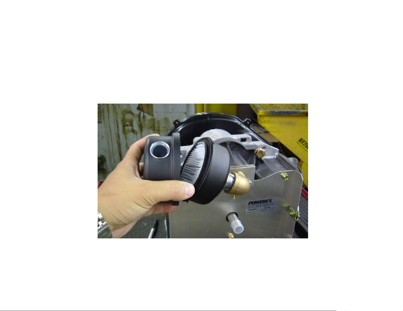
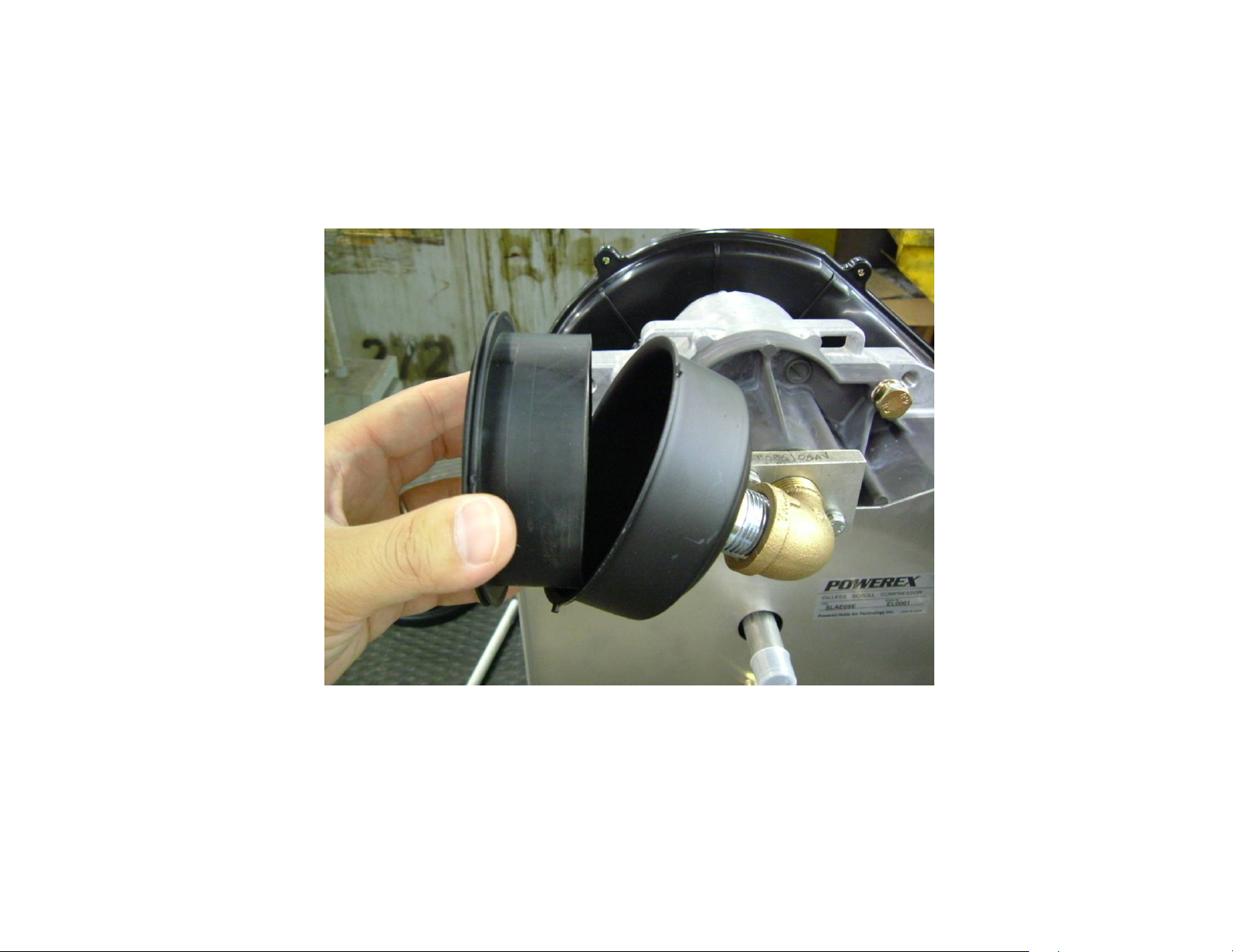
INTAKE AIR FILTER REPLACEMENT
every 2,500 HOURS – MAINTENANCE
1. Remove the Filter Cover.
4
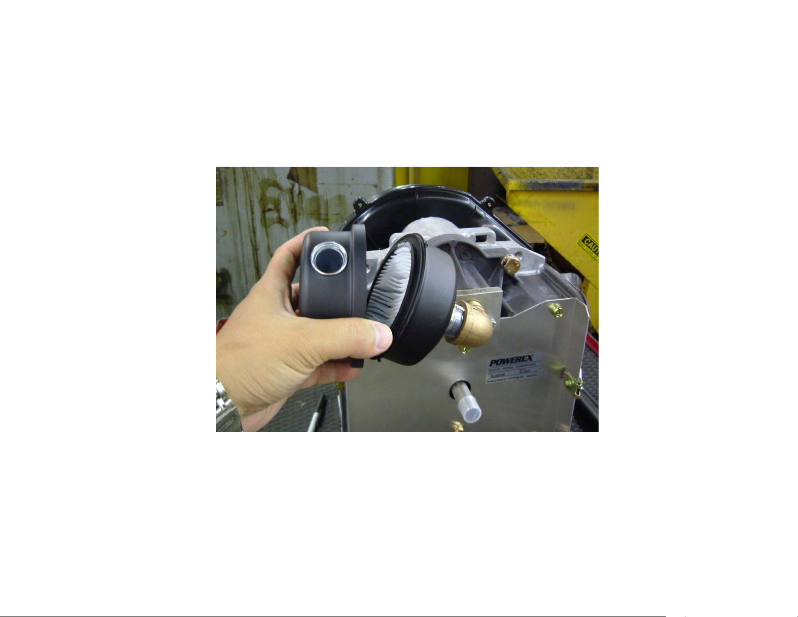
Page 5
2. Change the Filter Element (part number 91348550)
CAUTION
Do not attempt to clean the filter element. This filter requires replacement and
is to be replaced when contaminated.
5
Page 6
3. Reassemble the Filter Cover.
6
Page 7
COOLING FIN CLEANING
every 2500 HOURS - MAINTENANCE
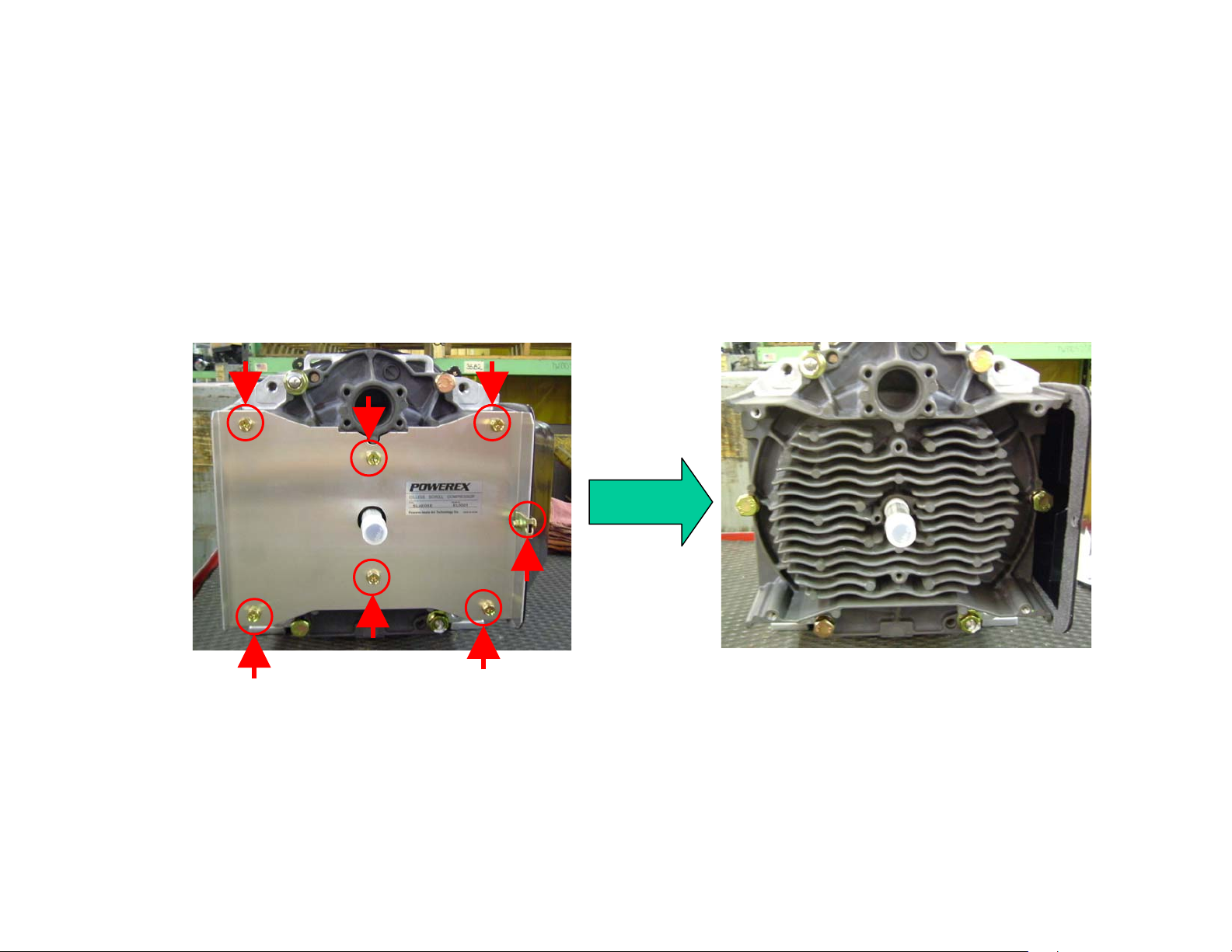
1. Remove the FS (Fixed Scroll) cover.
Remove these seven bolts.
7
Page 8
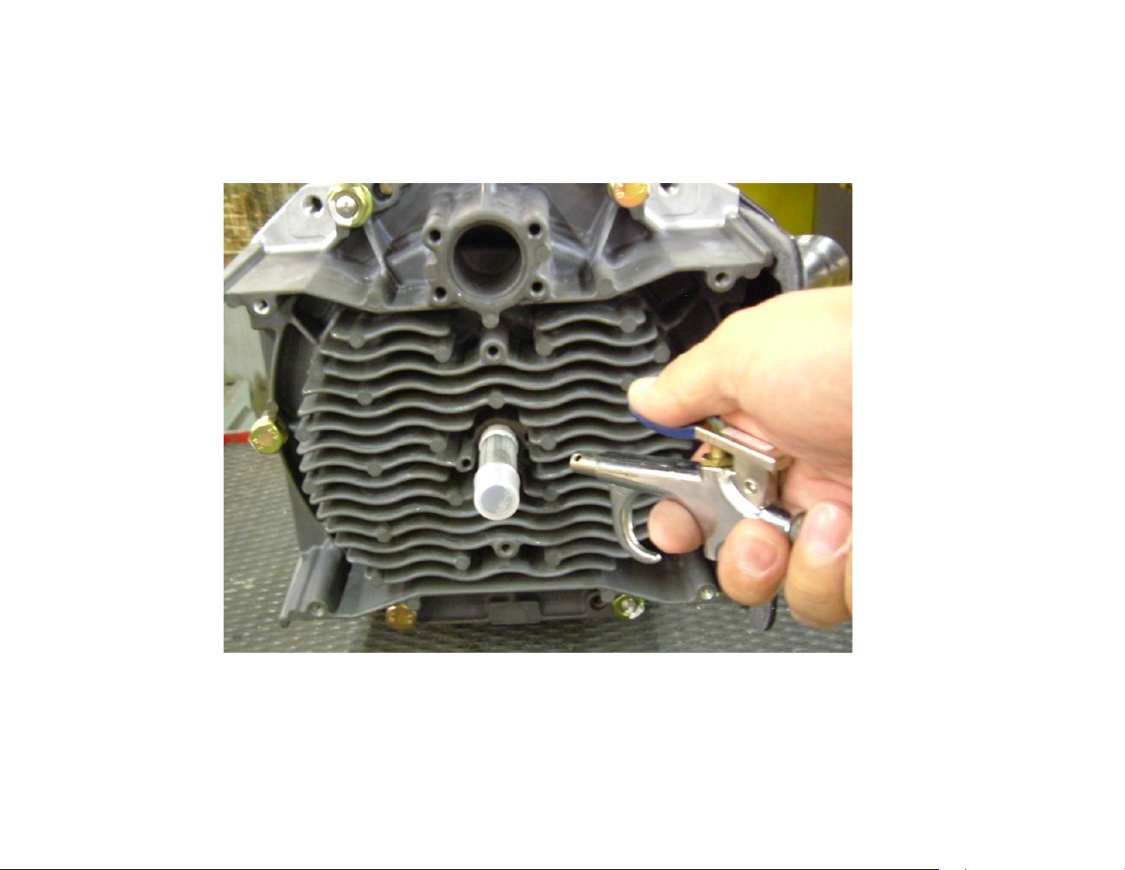
2. Clean FS fins with a blow gun.
8
Page 9
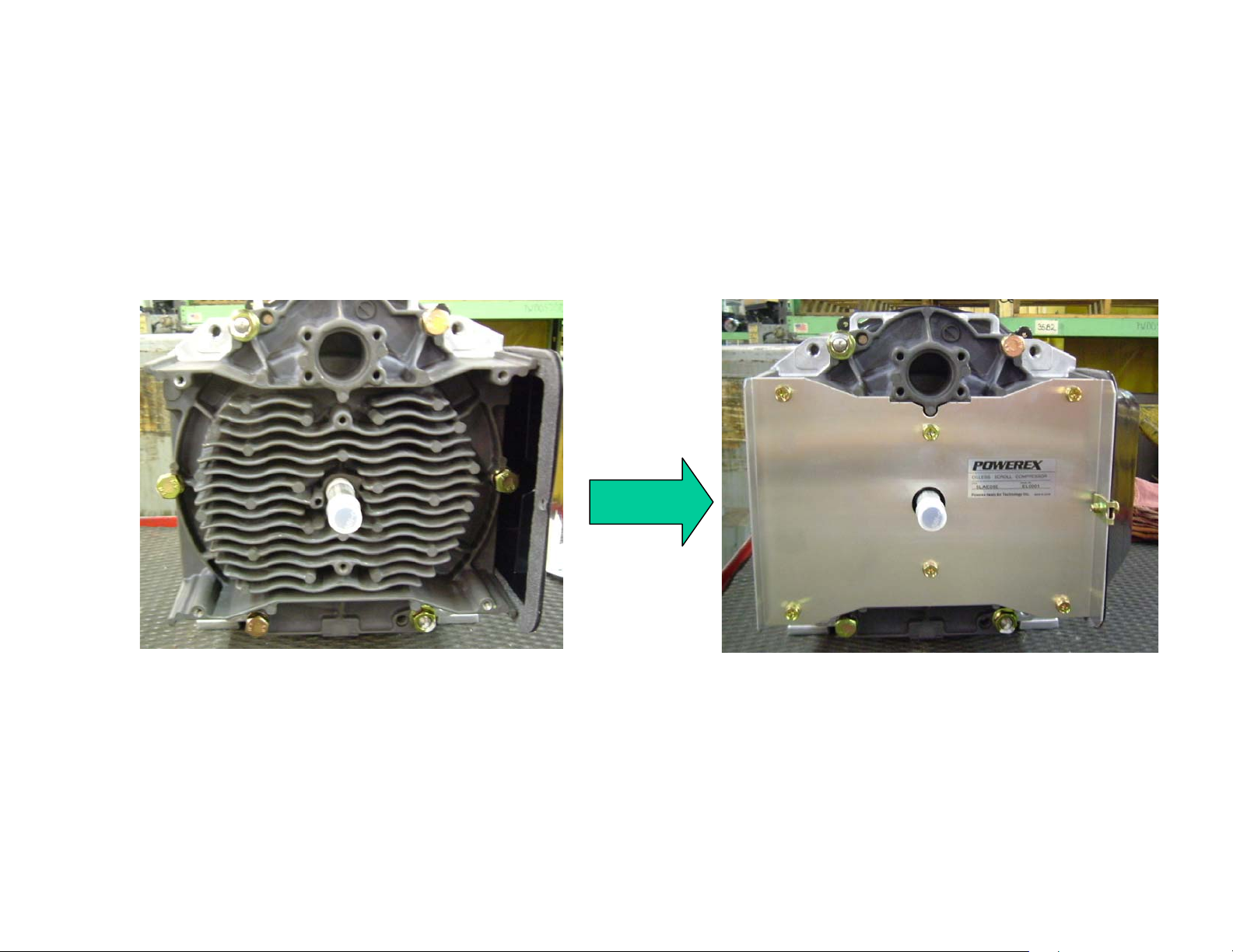
3. Reassemble the FS cover.
9
Page 10
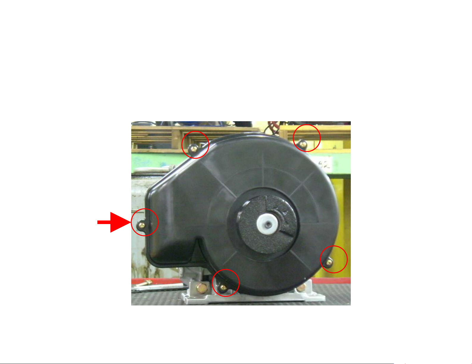
BLOWER FAN CLEANING
every 5,000 HOURS – MAINTENANCE
1. Remove five screws and take the Fan Cover off.
10
Page 11
2. Blow off dirt and dust
11
Page 12

FAN DUCT CLEANING
5,000 HOURS MAINTENANCE
Wipe out dirt and dust
12
Page 13

REGREASE BEARINGS
every 5,000 HOURS – MAINTENANCE (High pressure model)
10,000 HOURS – MAINTENANCE (Regular pressure model)
WARNING
Per OSHA regulations, ALL power must be locked out
before performing any maintenance.
1. OS BEARING
i. Remove the Plastic Dust Cap.
CAUTION
This service should be performed by an authorized
Powerex Service Center to avoid failure.
13
Page 14

ii. Rotate the Compressor Pulley until the grease fitting is visible through the dust cap hole.
seen from the front
14
Page 15

iii. Prepare a grease gun.
Grease Gun
Cartridge Grease
CAUTION
Use only Powerex genuine grease. Pump grease gun before using feeding (this eliminates
air from the grease passage of the extension adaptor).
Part Number: IP616200AJ (complete kit), IP600000AV (grease tube)
15
Page 16

iv. Use a grease gun extension adaptor to enlarge the grease fitting and supply
the power volume of grease as indicated below table.
Grease delivery (OS Bearing)
SLAE03E SLAE05E SLAE05EHP
1st time 2nd time 1st time 2nd time 1st time 2nd time
5 times 4 times 7 times 6 times 7 times 6 times
Note: Each pump of the grease gun equals 0.65 g of grease.
16
Page 17

v. Put the removed Plastic Dust Cap back.
17
Page 18

2. PIN CRANK BEARINGS
i. Remove the Fan Duct (2)
Remove these three bolts.
18
Page 19

ii. Remove FS (Fixed Scroll) Set
5 HP models only 5 HP models only
Remove bolts and nuts and remove the FS
19
Page 20

iii. Use a grease gun to enlarge the grease fitting and supply the power volume of grease
as indicated below table. Grease all three pin crank bearings from the grease fittings.
Grease fitting
Grease delivery (Pin crank bearings)
SLAE03E SLAE05E SLAE05EHP
1st time 2nd time 1st time 2nd time 1st time 2nd time
4 times 4 times 5 times 5 times 7 times 7 times
Notes: Each pump of the grease gun equals 0.65 g of grease.
CAUTION
Use only Powerex genuine grease. Pump grease gun before using feeding (this eliminates
air from the grease passage of the extension adaptor).
Part Number: IP616200AJ (complete kit), IP600000AV (grease tube)
20
Page 21

iv. Replace the FS set and fan duct (2). Tighten bolts and nuts temporarily and confirm if
crankshaft rotates smoothly by hand and tighten them firmly. Tightening torques are as
below.
Tightening torque
SLAE03E SLAE05E / SLAE05EHP
First Second First Second
17 in-ib 175 in-lb 17 in-ib 265 in-lb
NOTE: Assemble so that dust seal and tip seal will not drop between Orbit (OS) scroll and FS scroll set.
21
Page 22

TIP SEAL SET REPLACEMENT
every 5,000 HOURS – MAINTENANCE (High pressure model)
10,000 HOURS – MAINTENANCE (Regular pressure model)
WARNING
Per OSHA regulations, ALL power must be
locked out before performing any maintenance.
1. CONFIRMATION OF THE PARTS
i. Confirm if the Tip Seal you purchased is correct for the air end you are replacing (see below parts listing).
Tip Seal Set
SLAE03E SLAE05E SLAE05EHP
92834090 92832070 92832080
CAUTION
This service should be performed by an authorized
Powerex Service Center to avoid failure.
22
Page 23

ii. Confirm if the parts are correctly included.
HP Tip Seal for OS
HP Tip Seal for FS
LP Tip Seal for OS
Dust Seal
LP Tip Seal for FS
Backup Tube
HP = High Pressure LP = Low Pressure
FS = Fixed Scroll OS = Orbital Scroll
23
Page 24

2. REPLACEMENT
i. Remove the fan duct (2)
Remove these bolts.
24
Page 25

ii. Remove FS (Fixed Scroll) Set
5 HP models only 5 HP models only
Remove bolts and nuts and remove the FS
25
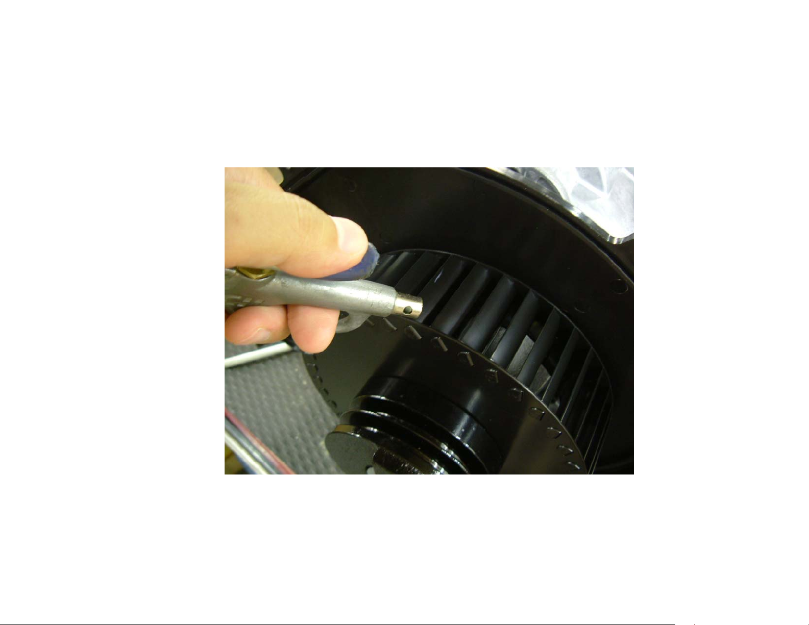
Page 26

iii. Remove the LP and HP Tip Seals, the Dust Seal and the Backup Tube from FS (Fixed
Scroll) and OS (Orbital Scroll) sets. Using the tip of a ball-point pen at the start will make
it much easier.
LP Tip Seal HP Tip Seal
※ You have to remove LP Tip Seal first
Dust Seal Backup Tube
※ Backup Tube is under the Dust Seal.
26
Page 27

iv. Remove dust from both OS and FS plates with clean cloth or air.
27
Page 28

v. Insert new HP Tip Seal from the center section of OS set so that there will be no
clearance at the start section.
Lip
(Inside)
Lip direction
Center
CAUTION
Tip Seals for OS and FS have opposing seal cut angles. Insert Tip Seal so
that the lip seal on the bottom of seal groove and inner side of scroll
spiral and the direction of lip faces the center of scroll spiral. This is to
be done both OS and FS sets, otherwise, air end cannot make enough air.
Lip
(Bottom Side)
28
Page 29

vi. Insert so that new LP Tip Seal will contact closely with HP Tip Seal inside scroll groove.
Notch
CAUTION
Insert approximately half of the LP Tip Seal and
remove the Tip Seal to confirm that a notch in the
Tip Seal has been achieved. This will prevent
movement during running. Before reinserting,
remove dust around the notch.
29
Page 30

vii. Insert LP Tip Seal all the way and cut excessive material.
30
Page 31

viii. Repeat the same procedure for FS Tip Seal set.
31
Page 32

ix. Insert new Backup Tube in the FS, then insert new Dust Seal on the Backup Tube.
Backup Tube Dust Seal
32
Page 33

x. After replacing Tip Seal Set, reassemble the FS set and fan duct (2) to the air end.
Tighten bolts and nuts temporarily and confirm if crankshaft rotates smoothly by hand
and tighten them firmly. Tightening torques are as below.
Tightening torque
SLAE03E SLAE05E / SLAE05EHP
First Second First Second
17 in-ib 175 in-lb 17 in-ib 265 in-lb
NOTE: Assemble so that dust seal and tip seal will not drop between Orbit (OS) scroll and FS scroll set.
33
Page 34

PARTS LIST
34
Page 35

Description Quantity
SLAE03E S LAE05E SLAE05EHP
Air end pulley 92843051 92549110 92549110 1
Key IP600600AV IP600600AV IP600600AV 1
Centrifugal fan IP601300AV IP601300AV IP601300AV 1
Fan Duct (1) IP601400AV IP601400AV IP601400AV 1
Fan Duct (2) IP601500AV 92519042 92519042 1
Fan Cover IP601700AV IP601700AV IP601700AV 1
Fan Duct Gasket (1) IP601800AV IP601800AV IP601800AV 1
Heat Insulation Pipe IP602000AV IP602000AV IP602000AV 1
Fan Duct Gasket (2) IP602400AV IP602400AV IP602400AV 1
Long Nipple 96647011 96647011 96647011 1
Dust Cap IP603500AV IP603500AV IP603500AV 1
Tip Seal Set 92834090 92832070 92832080 1
Filter Assembly ST073922AV ST073922AV ST073922AV 1
Filter Element 91348550 91348550 91348550 1
Street Elbow RB90SF34 RB90SF34 RB90SF34 1
Parts number for models
Adaptor Plate IP086100AV IP086100AV IP086100AV 1
Intake Gasket IP088200AV IP088200AV IP088200AV 1
Grease Gun Kit IP616200AJ IP616200AJ IP616200AJ 1
Grease Gun IP616100AJ IP616100AJ IP616100AJ 1
Grease (80g) IP600000AV IP600000AV IP600000AV 1
35
 Loading...