

Page 1
RS02
See Below
For
Alternatives
*
*Other lead code
options available
__
13/
RS03
Powerex, Inc., 200 Hillis Street, Youngwood, Pennsylvania 15697-1800 (412) 925-7272 Fast Recovery
Powerex, Europe, S.A. 428 Avenue
G.
Durand, BP107, 72003
Le
Mans, France (43) 41.14.14 Rectifier
13
125 Amperes Average
1400 Volts
I
o
MARKING
CASE
NUMBER
R50
DIMENSIONS
All
DIMENSIONS
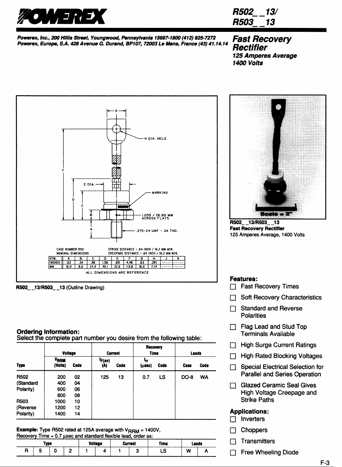
R502
__
13/R503
NOMINAL
__
13 (Outline Drawing)
Ordering Information:
Select the complete part number
Yoltage
Type
R502 200
(Standard
Polarity)
R503 1000
(Reverse
Polarity)
YRRM
(Yolts)
400
600
800 08
1200 12
1400
Code
02
04
06
10
14
IF(av)
........
++--+--1.055/26.80
ARE
you
desire from the following table:
Currenl
(A)
Code
125 13 0.7
ACROSS
.375-24
REfERENCE
(J1I8c)
flATS
UNf -2A
Recovery
Time
trr
Code
LS
MM
THO.
Case
00-8
Leads
Code
WA
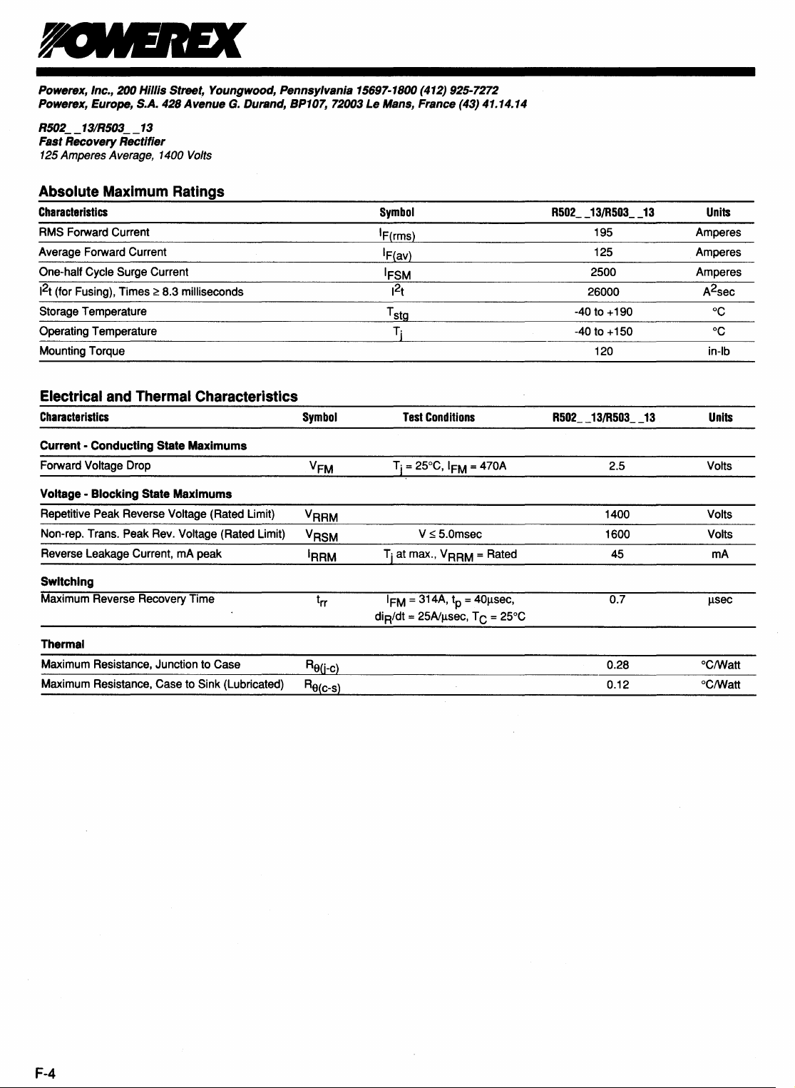
R502
__
13/R503
__
13
Fast Recovery Rectifier
125 Amperes Average, 1400 Volts
Features:
D Fast Recovery Times
D Soft Recovery Characteristics
o Standard
Polarities
o
Flag
Terminals Available
and
Reverse
Lead and Stud Top
o High Surge Current Ratings
D High Rated Blocking Voltages
D Special Electrical Selection for
Parallel
D Glazed Ceramic Seal Gives
High Voltage Creepage
Strike Paths
Applications:
D Inverters
and
Series Operation
and
Leads
W A
o Choppers
D Transmitters
o Free Wheeling Diode
F-3
Page 2
Powerex, Inc., 200 Hillis Street, Youngwood, Pennsylvania 15697-1800 (412) 925-7272
Powerex, Europe, S.A.
R502
__
13/R503
__
13
428
Avenue
G.
Durand, BP107, 72003 Le Mans, France (43) 41.14.14
Fast Recovery Rectifier
125
Amperes Average,
1400
Volts
Absolute Maximum Ratings
Characteristics
RMS Forward Current
Average Forward Current
One-half Cycle Surge Current
2
t
1
(for Fusing), Times ~ 8.3 milliseconds
Temperature
Storage
Operating Temperature
Mounting Torque
Symbol
IF(rms)
IF(av)
IFSM
J2
t
T
stg
Tj
Electrical and Thermal Characteristics
Characteristics
Current -Conducting State Maximums
Forward Voltage Drop
Voltage - Blocking State Maximums
Repetitive Peak Reverse Voltage (Rated Limit) VRRM
Non-rep. Trans. Peak Rev. Voltage (Rated Limit) VRSM
Reverse Leakage Current, rnA peak IRRM
Symbol
Test
Conditions
V ~ 5.0msec
Tj at max.,
VRRM = Rated
__
13/R503
__
R502
195 Amperes
125 Amperes
2500 Amperes
26000 A2sec
-40 to +190
to +150
-40
120
__
13/R503
R502
13
__
13
2.5 Volts
1400 Volts
1600 Volts
45
Units
°C
°C
in-Ib
Units
rnA
Switching
Maximum Reverse Recovery Time
Thermal
Maximum Resistance, Junction to Case
Maximum Resistance, Case to
Sink (Lubricated)
Re(j-c)
Re(c-s)
IFM = 314A, tp = 40llsec,
diR/dt = 25A1llsec, T C = 25°C
0.7
0.28
0.12
J.lSec
°ClWatt
°ClWatt
F-4
Page 3

Powerex, Inc., 200 Hillis Street, Youngwood, Pennsylvania 15697-1800 (412) 925-7272
Powerex, Europe, S.A.
R502
__
13/R503
__
13
428
Avenue
G.
Durand, BP107, 72003 Le Mans, France (43) 41.14.14
Fast Recovery Rectifier
125
Amperes Average,
1400
Volts
1000
Reverse Recovery
dt
(
t.+tn
aR~
=
di
,REC' = I RM,REC'
dt
Typical Reverse Recovery Time
)
-2-
x
IRM,REC'
t"
=~g~=
~~
Wave
Vs.
Rate
Form
of
Current Fall
I/)
::t
i-
eli
E
i=
>-
a;
>
0
u
II)
a:
~
a;
>
II)
a:
E
::J
E
.i(
10
~
100
01
Typical Reverse Recovery Charge Vs. Rate
R502_
13
R503._
13
~
~
.......
"-
~,
Typical Ratio
Rate
of
~
L
I
T = 25°C
10
of
Current
Current
T;
10
-
-
150°C
........
Fall, di H/dt,
Recovery
to
100
Rate
of
AI
J.l.S
of
Current Fall
Current Fall
1000
-
1"'"'1""
...
T=
150°C
\-
~
10
Rate
of
Current Fall, diR/dt.
",'"
iJII'
.......
""
T '25°C
I
II
I
[I
100
V
AI
./
J.l.S
1000
-i...
3
;>:
~
>
~
2
a:
E
II)
t 1
:l
U
'0
o
.~
0
a: 1
Rate
1,,,= 315A
10
of
Current
Fall
di./dt
100
A/J.l.s
1000
F-~
Page 4

Powerex, Inc., 200 Hillis Street, Youngwood, Pennsylvania 15697-1800 (412) 925-7272
Powerex, Europe, S.A.
R502
__
13/R503
__
13
428
Avenue
G.
Durand, BP107, 72003
Le
Mans, France (43) 41.14.14
Fast Recovery Rectifier
125 Amperes Average, 1400 Volts
10000
1-1-
10
1.0
.01
.001
R502
R50L.13
R502l3
.1
....
L..7 V
:.;,
IOii""
l/
10
Forward Current Vs. Forward Voltage Drop
..•
13
T 25"C
I
~l
T,15O"C
I.iiI
10IIII
~~,.
,.
Forward Voltage Drop, V,
Energy
Loss
Per Pulse for Sinusoidal Pulses
__
13
,.,.,
...
~i.-
......
l.....oo""
17'
~
i.ooo'"
I
~
...,
~
.............,
~Ioo'
IIIII
"
II
100 1000
Pulse Width,
\~P'«,,!!
\~
~
~.t.-
~J.
~I
I I I
M,
Volts
~
I
«,vo.
~
..
""
iPl""",
,..:..
1.~.
\r$J"'~
I
I I
I I
I I
I I
Jl.Sec
~!!!~
~
i/'
~
V
io'"
'"
l/"
II
T J = 150°C I I
~
~Io-
i
III
I
II
10.000
Transient Thermal Impedance Vs. Time
=
~30
U
°
c 25
,.j
~
20
U
£
c:
o 15
·u
c:
::l
....,
Q)
to
(J
c:
co
iQ.
05
.§
co
E
~
°0001
~
Calculation
and
1.
Conduction Losses
P
av(cond)
....
,..~
~"'"~
I--~
I--~
I--~
I--~
I--~
I--~
I--~
f--~
f--!-f--I-
1--11-->-
f--!--
1--1-
~
I--
~
001
of
~>-
1-->-
~I~I-
~>-
~f--
~I-
I-
...
~
01
~I-
1-->-
.I
~>-
~!--
~I-
1--11---1-
~I-
1---1I---
I
Time, t, Seconds
Fast Recovery Diodes
Allowable Case Temperature
= J/P x F
2. Reverse Recovery Losses (Approximate)
Pav(SW)
= 1/4 X V
x
~x
R
Trr2
dt 1 + 1/s
x
(~)2x
3. Maximum Allowable Case Temperature
T
C(max)
= T
- (P
av(cond)
+ P
j
av(sw) X Re(j-c))
Where:
P
av(cond)
= Forward Conduction Power Loss
P
av(sw)
= Reverse Recovery Power Loss
J/P
= Energy Loss per Pulse
F = Frequency
V
diR/dt
= Steady State Reverse Operating Voltage
R
in
Volts
= Rate of Decay of Forward Current
in
Hertz
in
Joules
in Amperes/)lsec
Trr
= Reverse Recovery Time
in
Microseconds
I-~
II
F X 1x10-
in
in
I
Watts
Watts
.........
1--1-
~~
~
f--!--
~
1--1-
~I-
f--I-
10
6
F-6
RO(j-C)
= Ratio of Recovery di/dt (
diE/dt
)
diR/dt
= Operating Frequency
= Maximum Allowable Case Temperature
in
Hertz
in
= Maximum Operating Junction Temperature
in
°C.
=
DC
Junction
in
°C/Watt.
to
Case Thermal Impedance
°C.
Page 5

Page 6

Powerex, Inc., 200 Hillis Street, Youngwood, Pennsylvania 15697-1800 (724) 925-7272
Code Tables
Average Current Rating for
'R' and
'T' type devices.
TYPE
CODE
Reverse recovery times for
'R' type devices.
TIME,
(!lsec)
CODE
Blocking voltage ratings for
'A' and
'C' type devices.
VOLTAGE
CODE
R4,T5
R5,R6
R7,R9,RA,RB
T6,
T7,
T8,
T9
TA,TB
Turn-off Times for
'T' type devices.
TIME,
(psec)
Phase
Cont.
8
10
15
20
25
30
35
40
50
60
70
80
100
125
150
175
200
250
If(av)
If(av/
If(av/
COOE
1O
1OO
0
9
8
7
6
B
5
L
4
3
2
C
1
K
M
N
P
a
R
Std.
Rec.
5.0
4.0
3.0
2.5
2.0
1.5
1.25
1.0
0.9
0.8
0.7
0.6
0.5
0.4
0.3
XX
AS
BS
CS
OS
ES
FS
GS
HS
JS
KS
LS
MS
PS
as
RS
Maximum gate current to fire for
'T' type devices.
Igt,
(rnA)
70
75
80
100
120
150
180
200
250
300
500
NA
CODE
7
K
6
5
F
4
G
3
H
2
1.
X
50
100
150
200
300
400
500
600
700
800
900
1000
1100
1200
1300
1400
1500
1600
1700
1800
1900
2000
2100
2200
2300
2400
2500
2600
2700
2800
2900
3000
3100
3200
3300
3400
3500
3600
3700
3800
3900
4000
4100
4200
4300
4400
4500
4600
F
A
G
B
C
0
E
M
S
N
T
P
PA
PB
PC
PO
PE
PM
PS
PN
PT
L
LA
LB
LC
LD
LE
LM
LS
LN
LT
CP
CA
CB
CC
CD
CE
eM
CS
CN
CT
DP
DA
DB
DC
DO
DE
OM
NOTE:
The
ratings
parameters as
in
defined
this
selector guide are
in
the
databooks
in
for
which
the
most
part based
specifications
on
the conditions
for
these devices
were
and
originally
published.
87
 Loading...