

Page 1
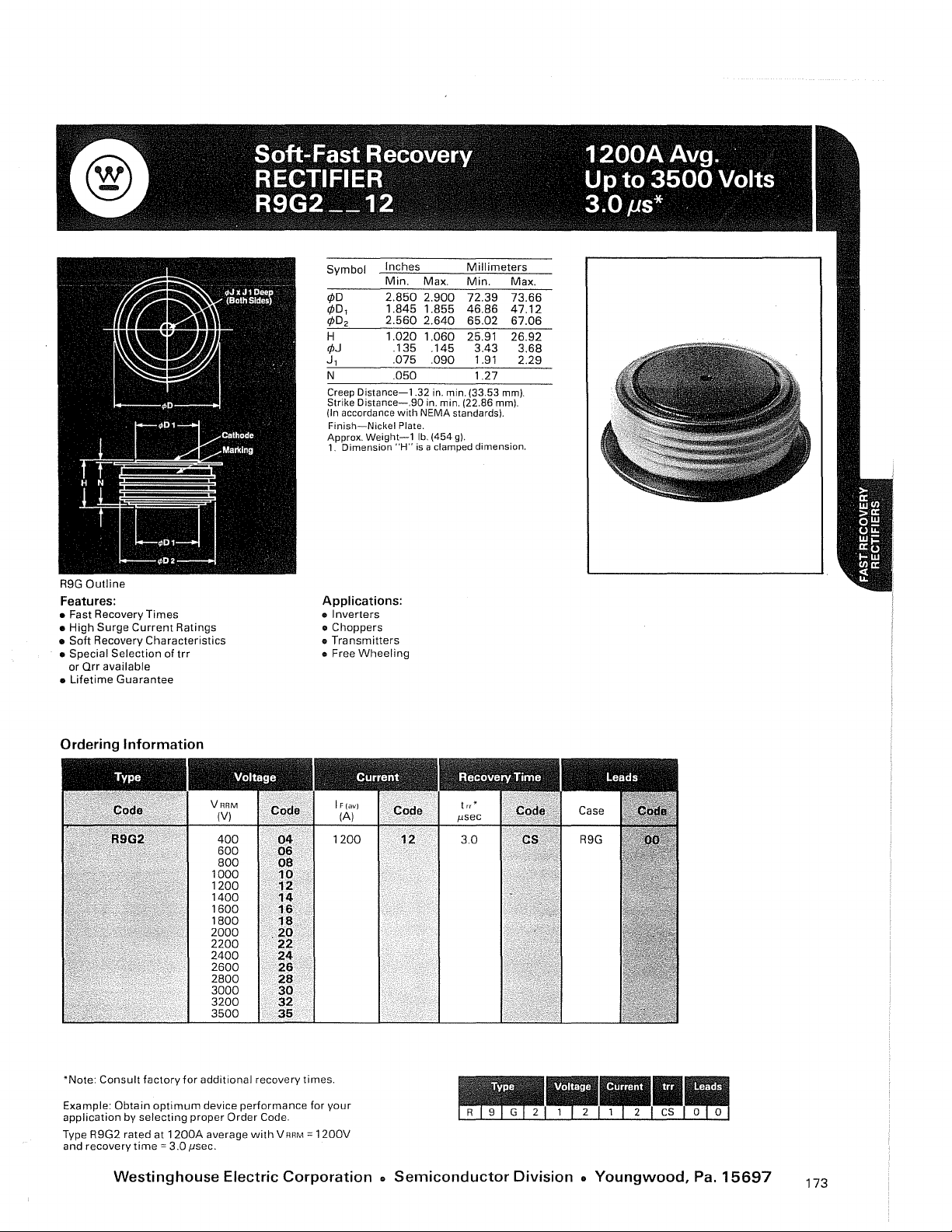
R9G
See Below
For
Alternatives
†
†Other lead code options available
Outline
Features:
• Fast Recovery Times
• High Surge
• Soft Recovery Characteristics
• Special Selection of
or
Qrr
• Lifetime Guarantee
Current
available
Ratings
trr
2
Distance-1.32
Distance-.eO
Weight-1
Dimension
Inches
Min.
2.850
1.845
2.560
1.020
.135
.075
.050
Symbol
cpD
cpD,
cpD
H
cpJ
,
J
N
Creep
Strike
(In accordance
Finish-Nickel
Approx.
1.
Applications:
• Inverters
• Choppers
•
Transmitters
• Free
Wheeling
Millimeters
Max.
Min.
2.900
72.39 73.66
1.855
46.86
2.640
65.02 67.06
1.060
25.91
.145 3.43
.090
1.91
1.27
in. min.
(33.53
in. min. (22.86 mm).
with
NEMA
Plate.
"H"
standards).
lb.
(454
g).
is a clamped dimension.
Max.
47.12
26.92
mm).
3.68
2.29
Ordering Information
'Note:
Consult factory
Example:
application
Type R9G2 rated at
and recovery
Obtain
by
selecting proper Order Code.
time'"
Westinghouse Electric
for
optimum
1200A
3.0
fJsec.
Code
400
600
800
1000
1200
1400
1600
1800
2000
2200
2400
2600
2800
3000
3200
3500
additional recovery times.
device performance for your
average
with
g:
08
10
12
14
16
18
.20
22
24
26
28
30
32
35
V
RRM
'"
1200V
1200
Corporation.
sec
Il
3.0
Semiconductor
Division.
Youngwood, Pa.
15697
173
Page 2
Blocl<ing
State
Maximums
Repetitive peak reverse voltage, V
Non-repetitive
V:S
Reverse
5.0
current,
transient
m sec
..............................
mA
CD
peak reverse voltage,
peak
....................
Symbol
.•.•••••.••..• V RAM
V
RSM
1
RAM
1~~~------------------------75--------------------------------~
Current
Conducting
(T
J =
RMS
Ave.
One-half
I't
A2
Max
Forward voltage drop at I
CDAt
CD
CD
0)
>
ci
o
25
OJ
OJ
~
g
State
150°C)
forward
forward
for fusing (for times = 8.3 ms)
sec
I't
1500
maximum
Per JEDEC RS-282, 4.01 F.3.
Consult
For
higher
Maximums
current, A .......................
current, A .......................
cycle surge
.....................................
of
A and T J = 25°C, V
recommended
current
package (t = 8.3 ms)
T J
voltages contact
Forward Voltage Drop
6.0-~
5.0
~=
R9G2 12
4.0·-----
'E
~
o
LL
Symbol
FM
Forward
1900
1200
14000
820,000
90 x 10
2.30
Current
CD. A ..............
A'
sec
FM
=
..................
mounting
Westinghouse.
..........
procedures.
1 F(rms}
1
1 FSM
Pt
I't
V
vs.
F(ov}
Forward Current, I FM, Peak Amperes
Switching
(T
J =
25°C)
Max. Reverse Recover
I
FM
= 1
500,
di
5
Thermal and Mechanical
Min.,
Min.,
Max.
Thermal
OJ'
({)
co
U
.8
c
o
'n
c
::J
""1
OJ
u
c
co
a3t::
~~
mU
EO
!...
~
I-N
tp = 1
R/dt = 25A/
Max. oper.
Max.
storage
mounting
resistance
with
double sided cooling
Junction
to case,
Case to sink, lubricated
.015
010
-;;}
00:
~
.001
Time
90
lIS
/1S,
T c = 25°C,
junction
torque, in lb.
temp
/1S
temp., °C
..
°C
..................
CD
......... , ......
.............
...............
CD
°C/Watt
.................
DC/Watt
.............
Transient Thermal Impedance
__
.D1.1
Time,
Symbol
trr
Symbol
T J
T slg
.
, . R
R
1.
seconds
8JC
8CS
3.0
-40to+150
-40
5000-6000
.018
.0075
vs.
Time
_
to
+190
10 100
174
Page 3
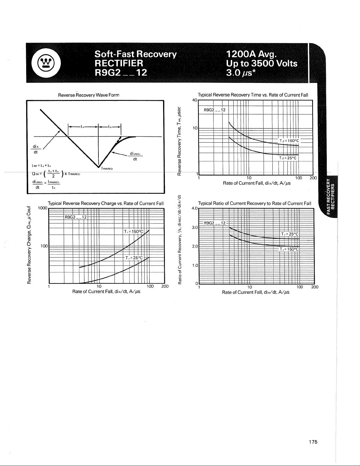
Reverse Recovery Wave Form
u
Q)
Typical Reverse Recovery Time
4Or---'-~~~~nT----~'-'-rT~~---'
~
:f
I-
al
E
f=
2:-
~
cr:
Q)
C/l
O-RR=t
ta-;tL)X-TRMIRECI
di
IAECi
= I "'liRECI Rate of Current Fall, di Rldt,
dt
tb
---
---------
------
---------
----------
--
~
-&!-
--------1
!===l=±:±±jj:Jj~==:l:::::1:;j:::1±jj:j:J;;:::::::;;!=-
1 10
vs.
Rate
of
Current Fall
Alps
Typical Reverse Recovery Charge
1000
1----
R9G2
12
100
Rate
of
Current
vs.
Rate
of
Current
Fall
T,=
150°C
V""
V-
T.I
....-
25°C
1'-
Alps
....-
...----1-""
10 100 200
Fall, di Aldt,
Typical Ratio
4.0 .
2.0
1.0
o
1
of
Current Recovery
Rate
of
Current Fall, di
10
to
Aid!,
Rate
of
Current Fall
Alps
100
200
175
Page 4
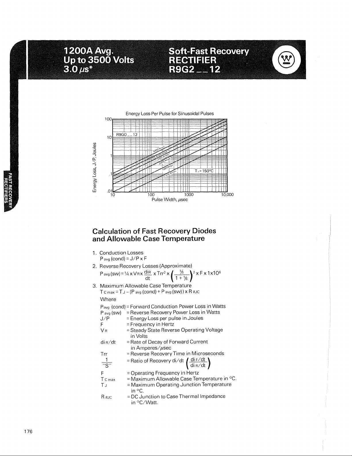
Energy
Loss
Per
Pulse
for Sinusoidal
Pulses
l00~~.'1_!_
10
R9GO
__
1 I
r.n
..92
::J
o
J
c.:
"-.
J
vi
r.n
..:J
>-
[?
OJ
C
UJ
Calculation
~,...-------
~·'7i""=--i:
.Q1
7
10
~
vlrl
of
~.I!~gll
k-./'v
Width,
r I
1000
I1Sec
100
Pulse
Fast Recovery Diodes
and Allowable Case Temperature
1. Conduction Losses
P
avg
(cond) =
2.
Reverse Recovery Losses (Approximate)
Pavg(SW)=%
3.
Maximum
T
C max = T J -
Where
Pavg
(cond) = Forward Conduction
P
avg
(sw)
J/P
F
VR
di
R/dt
Trr
1
"S"
F
T
C max
TJ
R
8JC
J/P
x F
XVRX ~ x
Allowable
(P
avg
= Reverse Recovery Power Loss in Watts
= Energy Loss per pulse in
= Frequency in Hertz
=
Steady State Reverse Operating Voltage
in Volts
= Rate
in
Amperesl
= Reverse Recovery
= Ratio of Recovery
= Operating Frequency
=
Maximum
=
Maximum
0c.
in
=
DC
Junction
in
°C/Watt.
Trr2
x
dt
Case Temperature
(cond) + P
of
Decay of Forward
(.-JL)2
avg
(SW))
flsec
Time
di/dt
Allowable
Operating
to Case
1 +
x F x 1 x10
Yo
x R
OJC
Power
Loss in Watts
Joules
Current
in Microseconds
( di
F/dt
R/dt
di
in
Hertz
Case Temperature in °C.
Junction
Thermal
Temperature
Impedance
j.;
10,000
6
)
176
Page 5
Powerex, Inc., 200 Hillis Street, Youngwood, Pennsylvania 15697-1800 (724) 925-7272
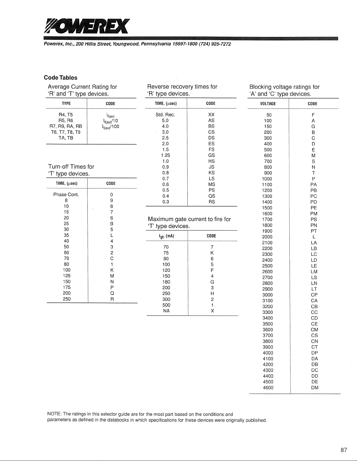
Code Tables
Average Current Rating for
'R' and
'T' type devices.
TYPE
CODE
Reverse recovery times for
'R' type devices.
TIME,
(!lsec)
CODE
Blocking voltage ratings for
'A' and
'C' type devices.
VOLTAGE
CODE
R4,T5
R5,R6
R7,R9,RA,RB
T6,
T7,
T8,
T9
TA,TB
Turn-off Times for
'T' type devices.
TIME,
(psec)
Phase
Cont.
8
10
15
20
25
30
35
40
50
60
70
80
100
125
150
175
200
250
If(av)
If(av/
If(av/
COOE
1O
1OO
0
9
8
7
6
B
5
L
4
3
2
C
1
K
M
N
P
a
R
Std.
Rec.
5.0
4.0
3.0
2.5
2.0
1.5
1.25
1.0
0.9
0.8
0.7
0.6
0.5
0.4
0.3
XX
AS
BS
CS
OS
ES
FS
GS
HS
JS
KS
LS
MS
PS
as
RS
Maximum gate current to fire for
'T' type devices.
Igt,
(rnA)
70
75
80
100
120
150
180
200
250
300
500
NA
CODE
7
K
6
5
F
4
G
3
H
2
1.
X
50
100
150
200
300
400
500
600
700
800
900
1000
1100
1200
1300
1400
1500
1600
1700
1800
1900
2000
2100
2200
2300
2400
2500
2600
2700
2800
2900
3000
3100
3200
3300
3400
3500
3600
3700
3800
3900
4000
4100
4200
4300
4400
4500
4600
F
A
G
B
C
0
E
M
S
N
T
P
PA
PB
PC
PO
PE
PM
PS
PN
PT
L
LA
LB
LC
LD
LE
LM
LS
LN
LT
CP
CA
CB
CC
CD
CE
eM
CS
CN
CT
DP
DA
DB
DC
DO
DE
OM
NOTE:
The
ratings
parameters as
in
defined
this
selector guide are
in
the
databooks
in
which
for
the
most
specifications
part based
for
on
the conditions
these devices
were
and
originally
published.
87
 Loading...