

Page 1
R722 05
See Below
For
Alternatives
*
*Other lead code
options available
Powerex, Inc., 200 Hillis Street, Youngwood, Pennsylvania 15697-1800 (412) 925-7272 Fast Recovery
Powerex, Europe, S.A. 428 Avenue
\
MARKING
r DIA.
G
DEEP
G.
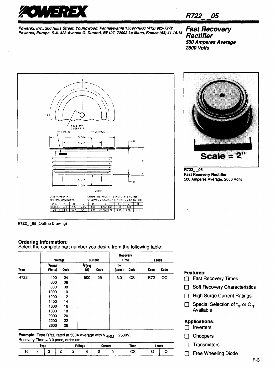
Durand, BP107, 72003 Le Mans, France (43) 41.14.14 Rectifier
500 Amperes Average
2600 Volts
TYP.
TYP.
\
CATHODE
~±=\r-~:
:~:::----t-----1~~
J*-
~======~======~
~~E
~'D"~
~
CASE
NUMBER
NOMINAL
DIMENSIONS
R722
__
o5
(Outline Drawing)
Ordering Information:
Select the complete part number
Voltage
Type
R722
VRRM
(Volts)
400
600
800
1000
1200
1400
1600
1800
2000
2200
2600
Code
COlA.
R72
IF(av)
04
06
08
10
12
14
16
18
20
22
26
~'I~
l
~
j I
DISTANCE'
~
INCH
118.5
1.17
INCH
129.7
from
the following table:
Recovery
Time
trr
(Illec)
Code
3.0
STRIKE
CREEPAGE
you
Current
(A)
500
L
ANODE
DISTANCE' .73
desire
Code
05
MM
CS
MIN.
MM
MIN.
E
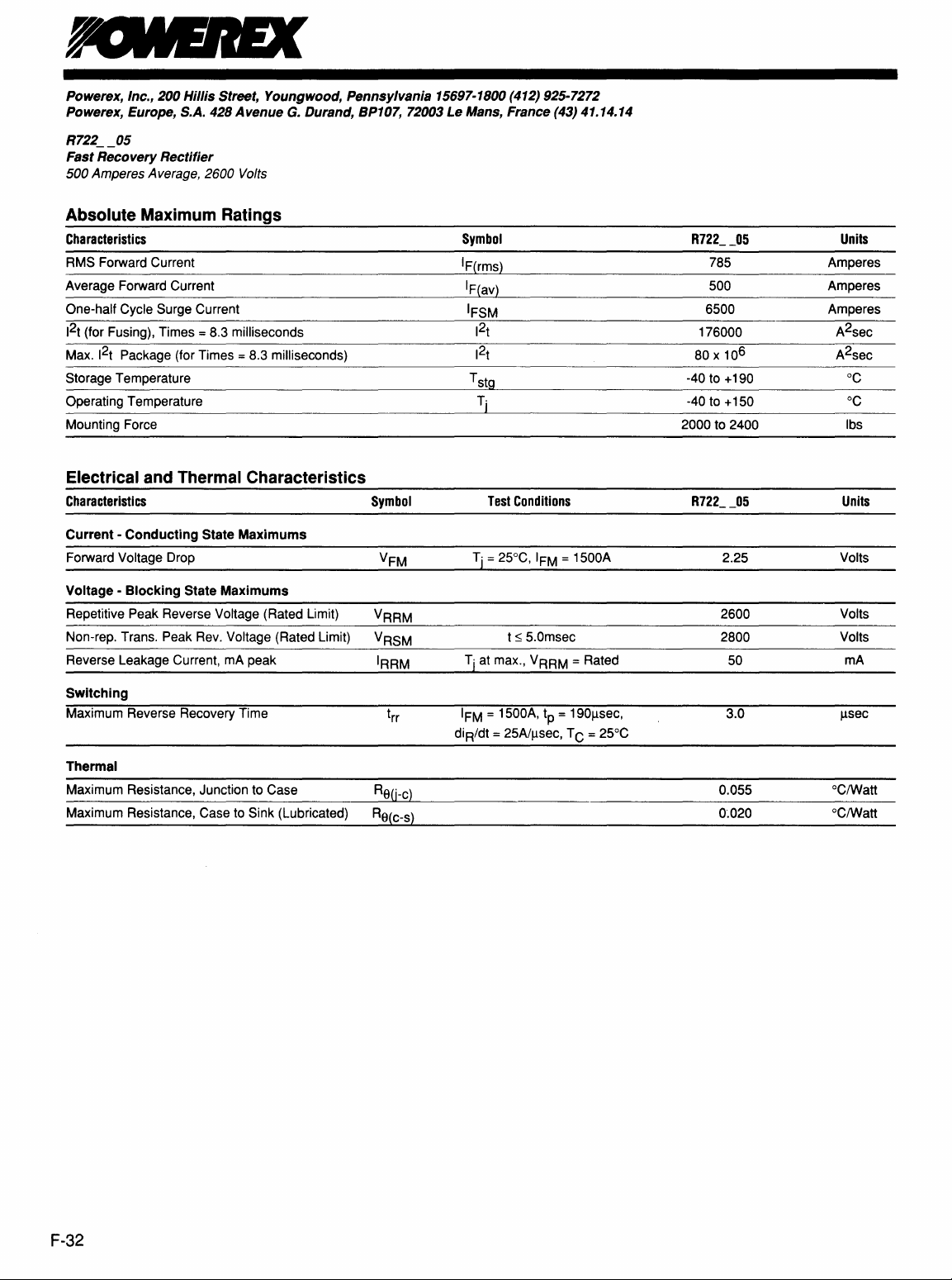
R722
__
05
Fast Recovery Rectifier
500
Amperes Average, 2600 Volts
Leads
Case
R72
Code
00
Features:
D Fast Recovery Times
D Soft Recovery Characteristics
D
High
Surge Current Ratings
D Special Selection of trr or Orr
Available
Applications:
D Inverters
o
Leads
o
D Choppers
D Transmitters
D Free Wheeling Diode
F-31
Page 2
Powerex,
Powerex, Europe, S.A. 428
R722
Fast
500
Inc.,
200
Hillis
Street,
__
05
Recovery
Amperes Average, 2600 Volts
Rectifier
Youngwood,
Avenue
G.
Durand,
Pennsylvania
BP107, 72003
15697-1800 (412) 925-7272
Le
Mans,
France
(43) 41.14.14
Absolute
Maximum Ratings
Characteristics
RMS Forward Current
Average Forward Current
One-half Cycle Surge Current
2
t (for Fusing), Times
1
2
1
Max.
t Package (for Times
Storage Temperature
Operating Temperature
Mounting Force
Electrical
and
Characteristics
= 8.3 milliseconds
= 8.3 milliseconds)
Thermal
Characteristics
Symbol
Current -Conducting State Maximums
Forward Voltage Drop
Voltage - Blocking State Maximums
Repetitive Peak Reverse Voltage (Rated Limit) VRRM
Rev.
Non-rep. Trans. Peak
Reverse Leakage Current, mA peak IRRM
Voltage (Rated Limit) VRSM
Switching
Maximum Reverse Recovery Time
Symbol
IF(rms}
IF(av}
IFSM
2
t
1
2
1
t
T
stg
Tj
Test
Conditions
t ~ 5.0msec
Tj at max., VRRM
= 1500A, tp = 1901lsec,
IFM
diR/dt
= 25A1llsec, T C = 25°C
= Rated
__
05
R722
785
500
6500
176000
6
80 x 10
-40 to +190
-40 to +150
2000 to 2400
R722
05
--
2.25 Volts
2600
2800
50
3.0
Units
Amperes
Amperes
Amperes
A2sec
A2sec
°C
°C
Ibs
Units
Volts
Volts
mA
sec
Il
Thermal
Maximum Resistance, Junction to Case Re(j-c}
to
Maximum Resistance, Case
Sink (Lubricated) Re(c-s}
F-32
0.055
0·.020
°C/Watt
°C/Watt
Page 3

Powerex, Inc., 200 Hillis Street, Youngwood, Pennsylvania 15697-1800 (412) 925-7272
Powerex, Europe, S.A.
R722
__
05
Fast Recovery Rectifier
500 Amperes Average, 2600 Volts
t.
01111
di IREel = IIIMIREel
dt
+ h )
=
-2-
(
lb
428
Avenue
Reverse Recovery
X IIIMIREel
G.
Durand, BP107, 72003 Le Mans, France (43) 41.14.14
Wave
Form
10.0
1.0
Typical
Rate
_R722
1
Reverse
of
Current
1 1
__
06
Rate
Recovery
Fall
"-
"
""",
~~
of
Current
Time
vs.
~
!Io.
...............
~
~~
--""""'
...
r--.......
10 100
Fall,
di
RI
dt,
AI
J.lS
~
TJ
= 150°C
III
m=25OC
Forward
=R722
5.0
4.0
3.0
2.0
1.0
o
10 100 1000 10,000
Voltage
05
Forward Current, I FM,
Drop
vs.
Forward Current
Peak
Amperes
=:
~06
U
o
g .05
N
~
~
.04
S
c:
.2 .03
~
::::I
..,
~
.02
,
1.
....
~
! 0
I-
III'"
001
Transient Thermal Impedance
"
.I
'til"
-~
.01
1
Time, t, Seconds
Vs.
Time
.-
.,
I
1#
10
100
F-33
Page 4

Powerex, Inc.,
Powerex, Europe, S.A.
R722
__
Fast
Recovery
500 Amperes Average, 2600 Volts
600
~
::a.
i
o
100
f
u
05
Typical
Rate
R722
200
Hillis
428
Rectifier
Reverse
of Current
I I
__
05
Street,
Avenue
Recovery
Fall
(
a:
.....
i
a:
10
~
Rate
Youngwood,
G.
Charge
.......
...
1-'
1-'
10 100
of Current
Pennsylvania
Durand, BP107, 72003
w.
~.".
"",
",
..",.
~"",
/~
/~
Fall,
di
RI
dt, AlIJS
15697-1800 (412) 925-7272
Le
Mans,
III
T'J~
150°C
~
l
'T'J
250C
~
France
(43) 41.14.14
Typical
Rate
=R722
o
1
of Current
4.0
3.0
2.0
1.0
Ratio
05
of Current
Fall
Rate
of Current
Recovery
10
Fall,
to
diR/dt,
Alps
TJ
=
25OC:
TJ=lSOOC
100
200
Energy
Loss
~2
10~~_~.
.OI~
1~~~~!I~i~111Iti~~~I~!!"~"II~~!i!ft1111
I
.001~~
10 100 1000 10.000
_05
111111
~
__
III
~~I~I~I
F-34
Per
__
Pulse
Pul~
for Sinusoidal
~I_l
__
jl~I~I~
Width,
Pulses
~ ~
/.tSeC
.......
1 I
I~~~~I~II
".
111111
Calculation of Fast Recovery Diodes
and Allowable Case Temperature
1.
Conduction Losses
P
av(cond)
= J/P x F
2. Reverse Recovery Losses (Approximate)
Pav(SW)
= 1/4 X
3. Maximum Allowable Case Temperature
C(max)
= T
(P
T
Where:
P
av(cond)
P
av(sw)
J/P
F
VA
diA/dt =
Trr
1
"S"
F
TC(max)
T
j
Re(j-c)
-
j
= Forward Conduction Power
= Reverse Recovery Power
= Energy Loss per Pulse
= Frequency
= Steady State Reverse Operating Voltage
in
Volts
Rate
in
Amperes/Jlsec
= Reverse Recovery Time
=
Ratio
= Operating Frequency
= Maximum Allowable Case Temperature
= Maximum Operating Junction Temperature
in
cC.
=
DC
in
cClWatt.
AX
VA x di
av(cond)
of Decay of Forward Current
of Recovery di/dt (diE/dt )
Junction
Tr? x
dt 1 + 1/s
+ P
in
(~)2X
av(sw) X Re(j-c))
Hertz
to
in
in
Case
Thermal Impedance
Loss
Joules
in
diA/dt
Hertz
Loss
Microseconds
F X
in
1x10-
in
Watts
Watts
6
in
cC.
Page 5

Powerex, Inc., 200 Hillis Street, Youngwood, Pennsylvania 15697-1800 (724) 925-7272
Code Tables
Average Current Rating for
'R' and
'T' type devices.
TYPE
CODE
Reverse recovery times for
'R' type devices.
TIME,
(!lsec)
CODE
Blocking voltage ratings for
'A' and
'C' type devices.
VOLTAGE
CODE
R4,T5
R5,R6
R7,R9,RA,RB
T6,
T7,
T8,
T9
TA,TB
Turn-off Times for
'T' type devices.
TIME,
(psec)
Phase
Cont.
8
10
15
20
25
30
35
40
50
60
70
80
100
125
150
175
200
250
If(av/
If(av/
COOE
If(av)
0
9
8
7
6
B
5
L
4
3
2
C
1
K
M
N
P
a
R
1O
1OO
Std.
Rec.
5.0
4.0
3.0
2.5
2.0
1.5
1.25
1.0
0.9
0.8
0.7
0.6
0.5
0.4
0.3
XX
AS
BS
CS
OS
ES
FS
GS
HS
JS
KS
LS
MS
PS
as
RS
Maximum gate current to fire for
'T' type devices.
Igt,
(rnA)
70
75
80
100
120
150
180
200
250
300
500
NA
CODE
7
K
6
5
F
4
G
3
H
2
1.
X
50
100
150
200
300
400
500
600
700
800
900
1000
1100
1200
1300
1400
1500
1600
1700
1800
1900
2000
2100
2200
2300
2400
2500
2600
2700
2800
2900
3000
3100
3200
3300
3400
3500
3600
3700
3800
3900
4000
4100
4200
4300
4400
4500
4600
F
A
G
B
C
0
E
M
S
N
T
P
PA
PB
PC
PO
PE
PM
PS
PN
PT
L
LA
LB
LC
LD
LE
LM
LS
LN
LT
CP
CA
CB
CC
CD
CE
eM
CS
CN
CT
DP
DA
DB
DC
DO
DE
OM
NOTE:
The
ratings
parameters as
in
defined
this
selector guide are
in
the
databooks
in
for
which
the
most
part based
specifications
on
the conditions
for
these devices
were
and
originally
published.
87
 Loading...