

Page 1
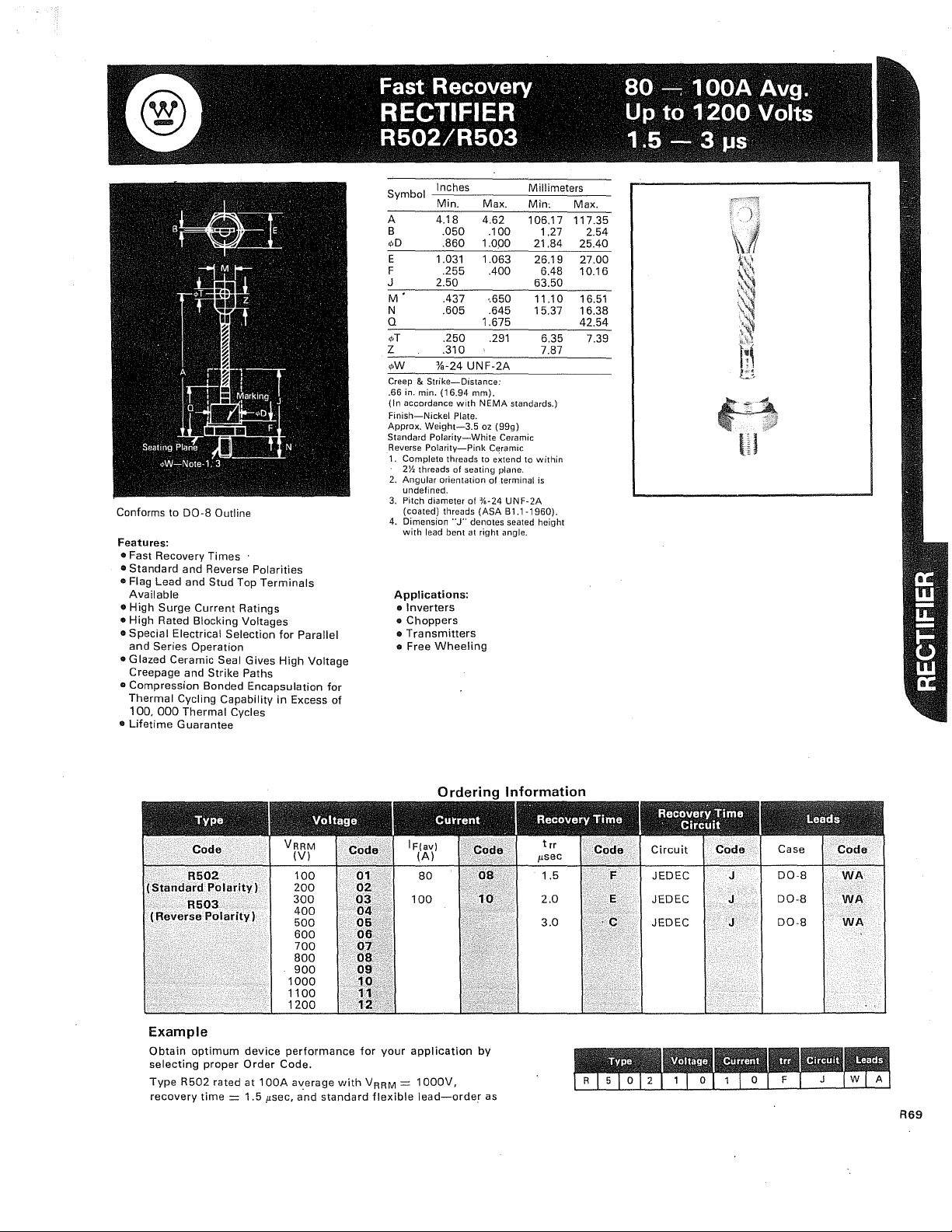
Conforms to DO-8 Outline
*
*Other lead code options available
Features:
..
Fast Recovery
..
Standard
..
Flag Lead and
Available
..
High
Surge
..
High Rated Blocking Voltages
..
Special Electrical Selection
and
Series Operation
..
Glazed Ceramic Seal Gives
Times
and Reverse Polarities
Stud
Top
Terminals
Current
Ratings
for
High
Creepage and Strike Paths
..
Compression Bonded Encapsulation
Thermal
100,
•
Lifetime
Cycling Capability
000
Thermal
Guarantee
Cycles
in
Parallel
Voltage
for
Excess of
Symbol
A
B
<pD
E
F
J 2.50
M'
N .605 .645
Q
1>T
Z
",W
Creep & Strike-Distance:
.66 in. min.
(In
Finish-Nickel
Approx.
Standard
Reverse
1, Complete threads to extend
2. Angular orientation of terminal
3.
4.
Inches
Min.
4.18 4.62
.050
.860
1.031 1.063
.255
.437
.250
.310
%-24
UNF-2A
(16.94
accordance
Weight-3.5
Polarity-Pink
2~
threads of seating plane.
undefined.
Pitch diameter
(coated) threads
Dimension
with lead bent
mm).
with N EMA
Plate.
Polarity-White
of
%-24
(ASA
"J"
denotes seated height
at
right angle.
Max.
.100
1.000
.400
,.650
1.675
.291
oz
(99g)
Ceramic
Ceramic
standards.)
UNF-2A
B1.1-1960).
Applications:
co
Inverters
..
Choppers
•
Transmitters
• Free
Wheeling
Millimeters
Min:
106.17
1.27
21.84
26.19
6.48
63.50
11.10
15.37
6.35
7.87
to
within
is
Max.
117.35
2.54
25.40
27.00
10.16
16.51
16.38
42.54
7.39
(Standard
(Reverse
Example
Obtain
selecting
Type
recovery
Code
R502
Polarity)
R503
Polarity)
optimum
proper
R502
time = 1.5
device
Order
rated at
VRRM
1000
1100
1200
performance
Code,
100A
flsec,
(V)
100
200
300
400
500
600
700
800
900
average
and
standard
Code
with
01
02
03
04
05
06
07
08<
09
.10
11
12
for
V
"',:;:
your
=
RRM
flexible
Ordering
IFlav)
(A)
application
1000V,
lead-order
Information
Code
by
as
t rr
flsec
1.5
Code
F
Circuit
Code
JEDEC J
JEDEC
JEDEC
Case
DO-8
J
J
DO-8
DO-8
Code
WA
WA
WA
R69
Page 2
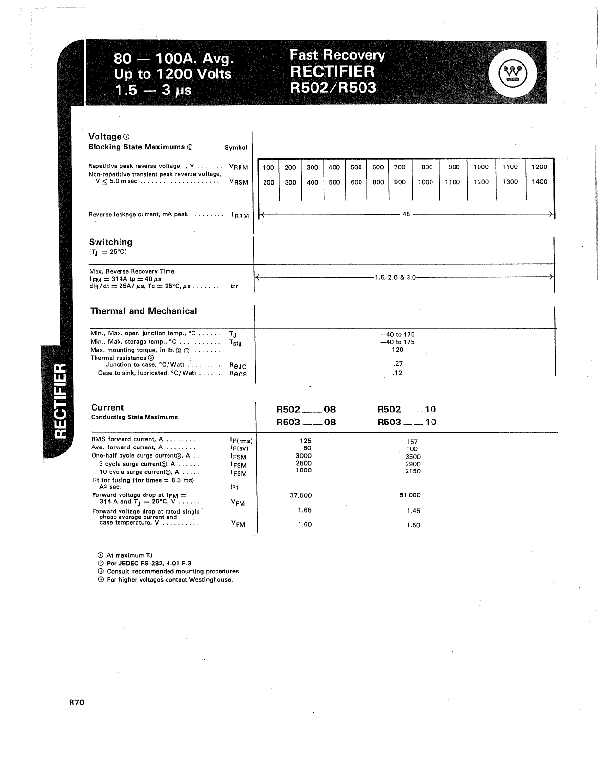
Voltage
Blocking
Repetitive peak reverse voltage
Non~repetitive
V:S
CD
State
Maximums
transient peak reverse voltage.
5.0
msec
.....................
<D
,V
.......
Symbol
VRRM
VRSM
100
200
200
300
300
400
400
500
500
600
600
800
700
900
800
1000
900
1100
1000
1200
1100
1300
1200
1400
Reverse leakage current,
mA
peak
Switching
(TJ
= 25°C)
Max. Reverse Recovery Time
IFM = 314A tp =
dlR/dt = 25A/
40!l'
!IS, Tc = 25°C,
!Is
Thermal and Mechanical
Min., Max. oper. junction temp.,
Min., Max. storage temp.,
Max. mounting torque,
Thermal resistance
Junction to
Case to
cD
case,
sink, lubricated, DC/Watt
DC ..........
in
Ib.®
DC/Watt
°c
®
........
Current
Conducting
RMS
Ave. forward
One-half cycle surge current®, A
12t for fusing (for times = 8.3 ms)
Forward voltage drop
Forward voltage drop
State
Maximums
forward current, A
current, A
3 cycle surge current®, A
10
cycle surge current®, A
A2
sec.
314
A and T
J
phase
average current and .
case temperature, V
........
........
at I FM
= 25°C, V
at
rated single
.........
.....
....
=
.....
...
.....
.......
.
.
.
..
.
.
.
.....
.....
.
.
.
.
.
.
~~-------------------------45--------------------------~
IRRM
1+--------------1.5,
trr
RaJC
Racs
IF(rms)
IF(av)
IFSM
IFSM
IFSM
2
1
t
VFM
VFM
R502
R503
37,500
__
__
125
80
3000
2500
1800
1.65
1.60
08
08
2.0 & 3.0-----------------iH
-40to175
-40
to
175
120
.27
.12
R502
__
10
R503
__
10
157
100
3500
2900
2150
51,000
1.45
1.50
R70
CD
At maximum
CD
Per JEDEC RS-2B2, 4.01 F.3.
<D
Consult recommended mounting procedures.
CD
For higher voltages contact
TJ
Westinghouse.
Page 3

~
~
~
u
I-
e
::J
E
Q)
c.
E
Q)
I-
Q)
a
§
E
'x
~
180
,...
170
r::::::
~
160
150
140
130
120
110
10
~
I--
Six Phase
,
(600 Square) /
0
90
80
0
R502-_08
R503
I I
Single Phase
t:::::
-"t':~
20
Average
__
08
(1800 Sine)
t:--....
.I
~t--..
Three Phase
(1200 Square)
40
Forward
r--..::
60
Current,
-+---I--I---;--I---;--\--1--+-+---;
I
~
80
IF
IAV).
R502-_08
R503
Amperes
100
__
08
120
200
<J)
;;;180
~
>i
160
<0:
:2
-
140
~
c'120
,2
a
100
'iii
<J)
0,
:u
~
a..
§
E
'~
:2
180
~
x
<0:
~
150
I::'.
:'!'
::J
150
E
Q)
c.
140
E
Q)
I-
Q)
<J)
130
to
u
E
::J
E
'x
'"
:2
110
80
60
40
20
12
)--1
I--
I-:
t;:;-"
o
./
.h
R502R503_
./
.....;;::
I
_08
.08
V
l.....'l
20
Average
./
7
'l
/./
Single
(1800 Sine)
T I
40
Forward
/'
'/
./
,/
1/
.....
V
Phase
Current.
-r
60
~
7
./
V
....
177
./
l./
~./
'\
Phase
Three
(1200 Square)
80
IF
IAV!.
/ /
V
/
17'
/'
/'
IV
1/1\
Six Phase _
0
,
(60
Square) _
100
Amperes
R502-_10
R503
V/
V
/
../
-
.120
__
10
<J)
~
to
~
x
<0:
~
>
~
C
,2
ro
c.
'iii
<J)
0
:u
::
0
a..
E
::J
E
'x
to
:2
250
230
210
190
170
150
130
110
90
70
50
10
30
~
r--
I--
t--
o
....
....
Forward Voltage Drop, VFM,
R502-_10
R502-_10
Three Phase
(1200 Square)
Single Phase
(1800 Sine)
V
../
Average
......-:
I--'
40
Forward
...-:/'
20
"-
./0;:
2
Volts
3
./
"
/'
./
./
Amperes
"
100
1/
/' /'
120
Six Phase
(600 Square)
"-
7
X
../
./
~
/'"
60
Current.
./
../
flO
IFIAV).
V
"-
./
100
Vl
Q)
:u
c.
E
~
1000
to
Q)
a..
~
i
~
::J
100
u
1"
'"
::
0
l'-
0
I=.
I---
F""'-'-
~TJ
o
20
R502.
R503 __
Average
1~5°C
_1
0
10
Forward
r'Y
Forward
40
Current,
-2
)/
t\
TJ
=
2r
1
Voltage Drop,
60
IF
IAV).
V
c
i
2
VFM,
80
Amperes
t::
Volts
I--
10'0
110
I--'
3
R71
Page 4

10n
O,--~--------------~----~-===~~=---I
~
UJ
JEDEC
Recovery Time Circuit
5
4
u
w
"'
2-
..:
'"
~trr
ai
3
E
i=
<:-
Q)
>
0
.2
u
Q)
a:
Q)
en
Q;
>
Q)
a:
T . I R R I r I I I
yp,ca everse ecovery ,me and Overshoot Current Vs.
-'Ratj
o
Rate
of
RD,
'1'
@
"L
m.LM
.,..
~
./
--~
@TC=175°C
"
~
~
k
l.--'
~
los @ITe = 25°C'IFM =
of
Revj'se
current
20
Reverse Current. diR/dt (Amps/usee)
30
for
314A
12.0
use~
R::;0.25
L<O.011'H
SCR,
To
Oscilloscope
~,~
V
./
trr @ITe!= 25°C
R502
40
./
alnd
R5U~
50
-...:::...-
100
80
60
40
20
o
tp=rrVLC
IFM=Ee/-yLfC
Recovery Time Waveform
Fast Switch
<ii
~
Q)
c.
E
~
Ul
.Q
H-!!+"""H-"H-H--H-+--!-++++++++-+'
Recovery Time Comparison for
Fast Switch and Conventional Rectifiers
(I'see)
Rectif'it
e:;;;U-;-,secT-
I '
I
, ' . ,
=1=
IVert,=poA/Di'r' i
:t
-l'-lI-lI-lI-lI-tI'--1'-lI-L
1+
,1
I i I
..j..
,
1.0
,Horiz.'f
..L1
'_1-",
1,
j 1
ill
H
i I
!----r---
"S(k./Div,
'
L.I---H
li!
.
:0
i
0
Rn
 Loading...